Model 610AR Installation and Maintence Instructions Drive Axle Air ...
Model 610AR Installation and Maintence Instructions Drive Axle Air ...
Model 610AR Installation and Maintence Instructions Drive Axle Air ...

You also want an ePaper? Increase the reach of your titles
YUMPU automatically turns print PDFs into web optimized ePapers that Google loves.
<strong>Model</strong> <strong>610AR</strong><strong>Installation</strong> <strong>and</strong><strong>Maintence</strong> <strong>Instructions</strong><strong>Drive</strong> <strong>Axle</strong> <strong>Air</strong>-RideSuspension System
<strong>Installation</strong> <strong>Instructions</strong> <strong>Model</strong> <strong>610AR</strong>COMPANY PROFILETuthill Transport Technologies is the new Line ofBusiness name arising from the acquisition <strong>and</strong>merger of two companies in the heavy-dutysuspension <strong>and</strong> off-road axle industries. Thesecompanies were formerly known as Fluidrive, Inc.of Brookston, IN <strong>and</strong> Reyco® Industries, Inc. ofSpringfield <strong>and</strong> Mt. Vernon, MO <strong>and</strong> Reyco®Canada of Grimsby, Ontario. Tuthill Corporationpurchased Fluidrive in December, 1998 <strong>and</strong>purchased Reyco® in February, 1999.Granning® <strong>Air</strong> Suspensions was founded in 1949in Detroit, Michigan. Granning’s product line wasconsolidated under Fluidrive, Inc. in 1985.Reyco® was founded in 1924 as Reynolds Mfg.Co. <strong>and</strong> assumed the Reyco® Industries, Inc.name in 1956 in Springfield. Reyco® Canadabegan at the current location in Grimsby, Ontario in1963. The Mt. Vernon facility was established in1973.ReycoGranning® air <strong>and</strong> steel spring suspensionsystems are sold to truck, trailer, <strong>and</strong> specialtyvehicle OEM's, <strong>and</strong> to truck equipment distributors.Tuthill Transport Technologies design, test,manufacture <strong>and</strong> market these products.Tuthill Transport Technologies is certified to theinternationally recognized ISO 9001 St<strong>and</strong>ard.This certification includes ReycoGranning®operations.ISO 9001 is the highest international qualityst<strong>and</strong>ard <strong>and</strong> is recognized worldwide by all majorcountries <strong>and</strong> corporations. To obtain certificationa company must undergo a series of rigorousaudits to remain certified <strong>and</strong> ensure consistentquality st<strong>and</strong>ards are being maintained. Thisquality st<strong>and</strong>ard was developed by theInternational Organization of St<strong>and</strong>ardization.Tuthill Corporation is a privately heldmanufacturing company with over 3,000employees <strong>and</strong> facilities on five continents.Tuthill’s corporate offices are located in Burr Ridge(Chicago), Illinois.<strong>Drive</strong> <strong>Axle</strong> <strong>Air</strong>-Ride Suspension System
<strong>Installation</strong> <strong>Instructions</strong> <strong>Model</strong> <strong>610AR</strong>SAFETY PROCEDURES & INFORMATION i.1SAFETY FIRST i.1OPERATOR SAFETY i.1Lifting i.1Parts H<strong>and</strong>ling i.1Welding i.1SUSPENSION SAFETY i.2Overloading the suspension i.2Torque i.2SUSPENSION INFORMATION SECTION i.3SUSPENSION INSTALLATION SECTION i.4Front Hangers i.4Upper <strong>Air</strong> Spring Brackets i.4Track Rod Bracket (Frame) i.5Spring Beams i.6<strong>Air</strong> Springs i.6<strong>Axle</strong> Seats i.7Shock Absorbers i.7Track Rod Bracket (<strong>Axle</strong>) i.8Track Rod i.8Height Control Valve i.9Height Control Valve Adjustment i.10<strong>Installation</strong> <strong>Instructions</strong>FINAL INSTALLATION TORQUE REQUIREMENTS i.11SUSPENSION ASSEMBLY OVERVIEW i.12<strong>Drive</strong> <strong>Axle</strong> <strong>Air</strong>-Ride Suspension System
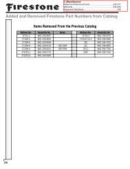
<strong>Installation</strong> <strong>Instructions</strong> <strong>Model</strong> <strong>610AR</strong>Safety Procedures & InformationSAFETY FIRSTBe sure to read <strong>and</strong> follow all installation <strong>and</strong>maintenance procedures.LIFTINGPractice safe lifting procedures. Consider size,shape <strong>and</strong> weight of assemblies. Obtain help orthe assistance of a crane when lifting heavyassemblies. Make sure the path of travel is clear.PARTS HANDLINGWhen h<strong>and</strong>ling parts, wear appropriate gloves,eyeglasses <strong>and</strong> other safety equipment to preventserious injury.WELDINGWhen welding, be sure to wear all personalprotective equipment for face <strong>and</strong> eyes, <strong>and</strong> haveadequate ventilation. When welding, protectspring beams <strong>and</strong> air springs from weld spatter<strong>and</strong> grinder sparks. Do not attach “ground”connection to springs.Under normal use, steel presents few healthhazards. Prolonged or repeated breathing of ironoxide fumes produced during welding may causesiderosis.Welding HelmetWelding ApronWelding Glovesi.1 <strong>Drive</strong> <strong>Axle</strong> <strong>Air</strong>-Ride Suspension System
<strong>Installation</strong> <strong>Instructions</strong> <strong>Model</strong> <strong>610AR</strong>WARNINGTorque WrenchOVERLOADINGOverloading is the practice of transporting cargosthat surpass the specified vehicle’s ratings.Overloading can cause component failure,resulting in accidents <strong>and</strong> injuries.This symbol indicates to the reader to use cautionwhen seen <strong>and</strong> to follow specific requirements orwarnings stated.CAUTION: Specific torque requirementsare recommended.TORQUEProper tightening of the U-bolt nuts <strong>and</strong> alignmentbolts are high priority items. A fastener system isconsidered “loose” any time the torque is foundbelow required values. Failure to maintain thespecified torque <strong>and</strong> to replace worn parts cancause component failure resulting in accident withconsequent injury.NOTE: It is extremely important after thefirst 1,000 to 3,000 loaded miles (1,600 -4,800 kms) of operation, <strong>and</strong> with eachannual inspection thereafter, that all of thebolt <strong>and</strong> nut tightening recommendationsbe followed. Any loose fasteners must beretorqued to comply with warrantyrequirements <strong>and</strong> to ensure long, troublefreeperformance.Safety Procedures & Information<strong>Drive</strong> <strong>Axle</strong> <strong>Air</strong>-Ride Suspension Systemi.2
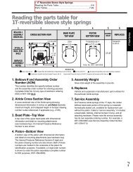
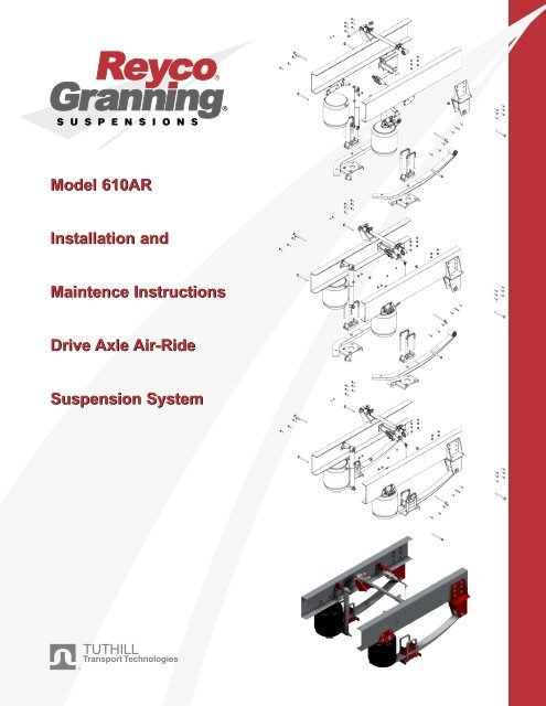
1 22267001235/8 BOLTSTYP 12X3/8 BOLTSTYP 2XTORQUE TO300 FT LBS3 1/46.2RIDE HEIGHT7281 1/4 TYP ON ALLFRAME HEIGHTS81/2 BOLTSTYP 4X916 1/44 PINIONANGLE3 5/82119701510 1/213 REF5/8 BOLTSTYP 4X6 1/25/8 BOLTSTYP 4X30 3125B25A10 11 532 11 512 13TORQUE TOTORQUE TOTORQUE TO300 FT LBS150-175 FT LBS25-30 FT LBS3 1/2REFTORQUE TO40-45 FT LBS29282120001NOTES:1. SUSPENSION RATINGS: GROUND LOAD (GAWR) 12,000-16,000 LBS.2. AXLE TRAVEL IS 2.3" UP AND 2.8" DOWNPINION ANGLE IS -4‘RIDE HEIGHT IS 6.2"3. AXLE SHOWN: 5.236 X 4.606 (19060S), REAR ENGINE4. SOME LINES LEFT OUT FOR CLARITY.5. FRAME ATTACHMENT FASTENERS SUPPLIED BY THE CUSTOMER ANDARE TO BE SAE GRADE 5 MINIMUM.6. WEIGHT OF SUSPENSION WITHOUT FASTENERS IS 276 LB.WEIGHT OF SUSPENSION COMPLETE IS APPROXIMATELY 289 LB.1815 16 171937 BEAM SPRING SPACING~ BOWL, HOUSING34 FRAME SPACINGASSEMBLE BOLT SIDE UP1 1/2 MIN GAPBETWEEN TRACKROD AND HIGHESTPOINT ON BOWLWELD AT ASSEMBLY~ CHASSISTORQUE TO14 400 FT LBS21BACK VIEW, NOT ATRUE PROJECTION.202633ITEM PART NO. DWG NO.DESCRIPTION1 2267001 96117 HANGER ASSEMBLY, LH2 2267002 96117 HANGER ASSEMBLY, RH3 2111301 94024 SPACER, WEAR4 2301701 91014 BOLT, M20x2.5 x 140 GR 10.95 1434401 93281 LOCK NUT, 3/4-16 UNF GR 86 2115301 94049#1 SPRING BEAM ASSEMBLY, LH7 2115302 94049#1 SPRING BEAM ASSEMBLY, RH8 2119901 94085 BRACKET9 2118106 94074#6 AXLE SEAT 4‘10 2083906 93397#6 U-BOLT, 3/4-16 UNF11 2085201 93403 FLAT WASHER, 3/4 (CLOSE FIT)12 1292001 93280 NUT, 1/2-13 UNC GR 513 T170562159 LOCK WASHER, 1/214 2119701 94083 BOTTOM PLATE ASSEMBLY, LH15 1735601 62158 BOLT, 7/8-9 UNC X 5 1/2 GR 516 1009201 93281 LOCK NUT, 7/8-9 UNC GR B17 T729271078 FLAT WASHER, 7/818 2108401 94011 AXLE BRACKET, TRACK ROD19 1642901 87109 TRACK ROD, ADJUSTABLE20 1827301 89479 FRAME BRACKET, TRACK ROD21 211970294083 BOTTOM PLATE ASSEMBLY, RH22 2120002 94086 MOUNTING BRACKET23 2016101 92289 SELF TAPPING SCREW, 1/4 X 2 1/224 2083801 93396 HEIGHT CONTROL VALVE25 N/A N/A SHOCK ABSORBER- KONI 90-189626 2118301 94076 UPPER SHOCK ABSORBER BRACKET27 1289001 82069 BOLT, 3/4-16 UNF X 7 GR 528 0821101 93280 NUT, 3/4-16 UNF2 REF29 T316462159 LOCK WASHER, 3/42 REF30 2116201 94058 UPPER AIR SPRING BRKT2 REF31 2077301 79167 AIR SPRING WITH UPPER BRACKET32 1524601 82069 BOLT, 3/4-16 UNF X 6 GR 833 2137001 94177 T.ROD FRAME DOUBLER34 2301801 94064 LOCKNUT- M20x2.5 CLASS 1027TORQUE TO150-175 FT LBSORIGREV.25B25ARELEASEDDESCRIPTIONTHIS DRAWING IS THE PROPERTY OF TUTHILL CORPORATION, AND IS NOT TO BE USEDIN ANY WAY DETRIMENTAL TO ITS INTERESTS. THIS DRAWING IS SUBJECT TO RETURNUPON REQUEST. ALL COPIES OF THIS ELECTRONIC DOCUMENT, WHETHER ELECTRONIC,PRINTED, OR OTHERWISE, ARE UNCONTROLLED DOCUMENTS.ALLOWABLE TOLERANCES UNLESS SPECIFIED: IN ADDITION, ALL PARTS MUST MEET REQUIREMENTSFRACTIONAL : +/- 1/16" [1.6mm] OF MS01000 REV A, "GENERAL DRAWING NOTES".2 DECIMAL PLACES: +/- 0.03" [0.8mm]3 DECIMAL PLACES: +/- 0.010" [0.25mm]ANGULAR : +/- 1 DEGREENOTES IN BRACKETS [] ARE METRIC UNITSTITLE:REAR SUSPENSION ASSEMBLY, -4‘ PINION,37" SPRING CENTERS, 34" FRAME- w/KONI SHK ABSDRAWN BY : G. SNYDERDRAWING DATE: 12/97CHECKED BY :APPROVED BY: RAMSUPERSEDES DRAWING OFPART NUMBER:11 525BILL OF MATERIAL <strong>610AR</strong> 94123#5BBDRAWING NUMBER:9287CHANGE NO.MODEL:SCALE: 1/412-10-97DATESPARTAN<strong>610AR</strong>SHEET:QTY<strong>Installation</strong> <strong>Instructions</strong> <strong>Model</strong> <strong>610AR</strong>Suspension InformationNormally, prior to any installations at an OEM,engineering contacts between companies havebeen made <strong>and</strong> all necessary information to makethe installation, has been exchanged. However, thefollowing steps are listed in the interest of allconcerned, <strong>and</strong> should be included in any OEMplan to install the suspension.PRIOR TO INSTALLATION1. The mounting height for the st<strong>and</strong>ard <strong>Model</strong><strong>610AR</strong> is 6.0 to 6.5 . This height represents thedistance from the bottom of the chassis to thecenterline of the axle. See Reyco drawing # 94123(page m.6), for details. This version shown isdesigned for rear engine installations.NOTE: All dimensions shown in drawings areexpressed in inches.Note: There are several versions, so be sure to getproper version for application.) Reyco drawing #94132 has information on frame drilling for thissuspension.2. The maximum axle capacity should be matchedfor compatibility with the <strong>Model</strong> <strong>610AR</strong> s capacityrange of 12000 to 16000 pounds.4 34 62422 2325A 1288802 79169 SLEEVE-SHOCK ABSORBER BUSHING25B 1289502 93403 WASHER-SHOCK ABSORBER BUSHINGINDUSTRIES INC.94123#5C5C3. The brake, axle, <strong>and</strong> other components shouldbe checked for compatibility <strong>and</strong> clearances withthe suspension.NOTE: Refer to REYCO assembly drawing.4. The chassis should be of suitable design for thesuspension to be installed. A crossmember whichties the left h<strong>and</strong> (LH) <strong>and</strong> right h<strong>and</strong> (RH) hangermounting positions together is required.5. If any welding is involved, all suspension partsmust be protected to avoid burns <strong>and</strong> weld splatter.IMPORTANT: Since this system doesNOT have an alignment feature, specialattention should be exercised to maintainalignment during the installation process.i.3 <strong>Drive</strong> <strong>Axle</strong> <strong>Air</strong>-Ride Suspension System
2267001<strong>Installation</strong> <strong>Instructions</strong> <strong>Model</strong> <strong>610AR</strong>281 22267001324 34TORQUE TO300 FT LBS10 1/25/8 BOLTSTYP 4X303112 13TORQUE TO25-30 FT LBSSUSPENSION INSTALLATIONFRONT HANGERS1. The distance between the outer sides of thechassis rails is 34.0 , which results in a springcenter spacing of 37.0 . However, dimensionsmay vary by model, check print.NOTE: If frame has not been drilled prior toinstallation, typically obtain applicable parts,clamp in-place, mark side rails of frame at holdlocations, <strong>and</strong> match drill holes as required. Thefollowing instructions will pertain to a pre-drilledframe.2. Locate LH <strong>and</strong> RH Hangers (1, 2) on side offrame, per assembly drawing. Recheck location<strong>and</strong> squareness, <strong>and</strong> install proper 5/8 fasteners(customer supplied).3. Torque hanger mounting bolts to properspecifications, (Customer Specs).NOTE: Item numbers (in circles) refer to partnumbers listed on Drawing # 94123, sheet 10.UPPER AIR SPRING BRACKETS,WITH AIR SPRINGS ATTACHED1. Obtain LH <strong>and</strong> RH Upper <strong>Air</strong> Spring Brackets(30), (with air springs attached).2. Locate on frame per assembly drawing.3. Check squareness of setup. When all parts areproperly positioned, install 5/8 fasteners(customer supplied), per print.4. Torque fasteners to proper specifications.Front Hangers & Upper <strong>Air</strong> Spring Brackets<strong>Drive</strong> <strong>Axle</strong> <strong>Air</strong>-Ride Suspension Systemi.4
<strong>Installation</strong> <strong>Instructions</strong> <strong>Model</strong> <strong>610AR</strong>Track Rod BracketTRACK ROD BRACKET, FRAMEMOUNTING1. Obtain Track Rod Bracket (20) that mounts toframe. Note: location varies with seat angles, <strong>and</strong>type of rod used.2. Depending upon application, locate on frameper print.3. If using optional 2137001 Frame Doubler (33)install it.NOTE: TTT recommends using doubler if noprevious history exists.4. Install proper 1/2 fasteners (customersupplied).5. Torque fasteners to proper specification.ASSEMBLE BOLT SIDE UP1 1/2 MIN GAPBETWEEN TRACKROD AND HIGHESTPOINT ON BOWL20263321252725B25A11 5TORQUE TO150-175 FT LBSi.5 <strong>Drive</strong> <strong>Axle</strong> <strong>Air</strong>-Ride Suspension System
<strong>Installation</strong> <strong>Instructions</strong> <strong>Model</strong> <strong>610AR</strong>1 21 234 34 6 7TORQUE TO300 FT LBS34 34TORQUE TO300 FT LBS910 11 5TORQUE TO 25B300 FT LBS 25A32 11 5TORQUE TO150-175 FT LBS12 13TORQUE TO25-30 FT LBSSPRING BEAMS1. Obtain LH <strong>and</strong> RH spring beam assemblies(6),(7)2. Install beams into front hangers using 20MMbolts (4) <strong>and</strong> locknuts (34). Be sure to install oneeach of the 2111301 Wear Spacers (3) on eachside of each spring beam. Snug fasteners, but donot tighten.Spring Beams & <strong>Air</strong> Springs910 11TORQUE TO300 FT LBS5 25A3225B11 5TORQUE TO150-175 FT LBSAIR SPRING ASSEMBLY:1. Align stud provided at lower piston of each airspring (31), with hole in each spring beamassembly.12 13TORQUE TO25-30 FT LBS2. Install 1/2 lockwasher (12) <strong>and</strong> nut (13) ontoeach stud, <strong>and</strong> torque to 25-30 Ft-lbs.<strong>Drive</strong> <strong>Axle</strong> <strong>Air</strong>-Ride Suspension Systemi.6
<strong>Installation</strong> <strong>Instructions</strong> <strong>Model</strong> <strong>610AR</strong><strong>Axle</strong> Seats & Shock AbsorbersAXLE SEATS AND AXLE1. Obtain proper axle, LH <strong>and</strong> RH axle seats (9),<strong>and</strong> bottom plate assemblies (14), (21) with allparts in proper location guide U-Bolts (10) aroundaxle, aligning seats, <strong>and</strong> thru bottom plates.Loosely install the 3/4 locknuts (5) <strong>and</strong>flatwashers (11), to the U-Bolts.2. When all parts are together torque the 3/4locknuts to 300-325 Ft-lbs. Use criss-crosssequence, in 50 Ft-lb increments to load the 3/4U-Bolts evenly.SHOCK ABSORBER INSTALLATION1. Obtain the RH <strong>and</strong> LH Upper Shock AbsorberBrackets (26).2. Install the brackets on each side of the frame,using 5/8 fasteners (customer supplied), loosely.3. Obtain shock absorbers (25) <strong>and</strong> with large endup, install one 3/4 bolt (32), (11), with one 3/4flatwasher (11) on each side of the rubber shockbushing. Insert through the upper shock bracket<strong>and</strong> frame, <strong>and</strong> then install the 3/4 locknut (5).4. Complete the upper shock installation on theother side.21200015/8 BOLTSTYP 4X26286.2RIDE HEIGHT67914214 PINIONANGLE2610 1/2510 11 5TORQUE TO300 FT LBS25B25A32 11 5TORQUE TO150-175 FT LBS5. Using one 3/4 bolt (32), (11) the 3/4flatwashers (11) on each side of the shock bushing,<strong>and</strong> 3/4 locknut (5). Similarly install the lowerend of both shocks into the lower brackets on theLH <strong>and</strong> RH axle bottom plates (14, 21).525A25B25A25B6. Tighten the 3/4 locknuts at the ends of theshock absorbers to 150-175 Ft-lbs.7. Tighten the 5/8 upper shock bracket nuts toOEM s spec.32 11 521TORQUE TO150-175 FT LBSi.7 <strong>Drive</strong> <strong>Axle</strong> <strong>Air</strong>-Ride Suspension System
<strong>Installation</strong> <strong>Instructions</strong> <strong>Model</strong> <strong>610AR</strong>Gap is clearof interferrence21200011819Weld LocationWITH THE AXLE BLOCKED UPROUGHLY AT RIDE HEIGHT,PERFORM:TRACK ROD BRACKET, AXLEMOUNTING:1. Obtain Track Rod Bracket (18), that mounts toaxle. Note: location varies with frame width, seatangles, etc.2. Depending upon application, locate on axle perprint.NOTE: This location must be done at properride height. Track Rod should be as level aspossible at ride height.3. When all is properly located, weld to axle perprint on page m.6.Track Rod AssemblyAssemble Bolt Side Up19202623TRACK ROD INSTALLATION:1. Obtain the applicable track rod (19), <strong>and</strong> installthe 7/8 bolts (15), 7/8 locknuts (16), <strong>and</strong>flatwashers (17), at each end. Snug the 7/8locknuts, but do not tighten.2. With the suspension at proper ride height,tighten the 7/8 track rod end nuts to 400-425 Ftlbs.1516173. With the track rod adjusted to optimum length(spring beams parallel <strong>and</strong> centered), tighten thetrack rod clamp nuts to 125-150 Ft-lbs.<strong>Drive</strong> <strong>Axle</strong> <strong>Air</strong>-Ride Suspension Systemi.8
<strong>Installation</strong> <strong>Instructions</strong> <strong>Model</strong> <strong>610AR</strong>Height Control AdjustmentsHEIGHT CONTROL VALVEINSTALLATION1. One height control valve (HCV)(24) <strong>and</strong>linkage assembly (35) is used to control the driveaxle. The air springs <strong>and</strong> HCV s are connected by1/4 minimum inside diameter tubing (customerfurnished). Ensure the valve is positionedproperly, per the print (as there are variations).2. The HCV is attached to the sides of the frameby utilizing the mounting bracket included (22).This is attached by 3/8 bolts (customerfurnished). Tighten to specs.3. Assemble the linkages, per the assemblydrawing. The linkage is attached to the axledifferential bowl using the mounting bracketincluded (8). Locate properly <strong>and</strong> weld to axlebowl.4. Tighten all ReycoGranning furnished 1/4 nutsto 5 Ft-lbs.5. The air supply for the suspension should betaken from an air supply reservoir. Position thePressure Protection Valve/Filter between thereservoir <strong>and</strong> the HCV.6. As with any air pressure system, whenplumbing is completed, check for leaks, <strong>and</strong>eliminate leakage.3/8 BOLTSTYP 2X8i.9 <strong>Drive</strong> <strong>Axle</strong> <strong>Air</strong>-Ride Suspension System
<strong>Installation</strong> <strong>Instructions</strong> <strong>Model</strong> <strong>610AR</strong>3/8 BOLTSTYP 2XDisconnect linkage here8Adjust hereHEIGHT CONTROL VALVEADJUSTMENT (FOR UNITS SOEQUIPPED)1. Position the assembled, unladen vehicle on alevel floor with air pressure of 90+ psi, availableto the system.2. Disconnect linkage <strong>and</strong> exhaust all air from thesprings.3. Reconnect the linkage, <strong>and</strong> let the springsinflate. Measure frame-to-axle centerline distance.If correct, no adjustment is needed. If incorrect,use adjustment feature on linkage, or on HCV.4. Recheck by disconnecting the linkage <strong>and</strong>deflating the spring. When the linkage isreconnected, the springs should reinflate to theproper mounting height.Height Control Adjustments<strong>Drive</strong> <strong>Axle</strong> <strong>Air</strong>-Ride Suspension Systemi.10
<strong>Installation</strong> <strong>Instructions</strong> <strong>Model</strong> <strong>610AR</strong>Torque RequirementsThe <strong>Model</strong> <strong>610AR</strong> suspensions require, by design, a minimum of maintenance. However, suspensions in normal operation require periodicchecks to assure continued trouble-free performance.TORQUE REQUIREMENTS (Verify with each inspection.)With the air system operating, make sure all fasteners are tightened to the following levels:1. U-Bolt Nuts, (3/4”) 300-325 Ft-lbs. (410-440 Nm).2. Front Spring Beam Pivot Nut, (20MM) 300-325 Ft-lbs. (410-440 Nm).3. Shock Absorber End Nut, (3/4”) 150-175 Ft-lbs. (205-240 Nm).4. Track Rod End Nut, (7/8”) 400-425 Ft-lbs. (545-580 Nm).5. Track Rod Clamp Nut, (5/8”) 125-150 Ft-lbs. (170-205 Nm).6. Upper <strong>Air</strong> Spring Mount Nut, (3/4”) 40-45 Ft-lbs. (55-60 Nm).7. Lower <strong>Air</strong> Spring Mount Nut, (1/2”) 25-30 Ft-lbs. (35-41 Nm).8. <strong>Air</strong> Valve <strong>and</strong> Linkage Nut, (1/4”) 5 Ft-lbs. (7 Nm).ft lb = Foot - Pounds; Nm = Newton - Metersi.11 <strong>Drive</strong> <strong>Axle</strong> <strong>Air</strong>-Ride Suspension System
<strong>Installation</strong> <strong>Instructions</strong> <strong>Model</strong> <strong>610AR</strong>SUSPENSION ASSEMBLYOVERVIEW1. Organize suspension components.2. Attach air springs/shock absorbers, hieghtcontrol valve <strong>and</strong> hangers to the frame.3. Attach spring beams to suspension.4. Attach track rod.Suspension Assembly Overview<strong>Drive</strong> <strong>Axle</strong> <strong>Air</strong>-Ride Suspension Systemi.12
<strong>Installation</strong> <strong>Instructions</strong> <strong>Model</strong> <strong>610AR</strong>Steer <strong>Axle</strong> <strong>Air</strong>-Ride Suspension System
<strong>Installation</strong> <strong>Instructions</strong> <strong>Model</strong> <strong>610AR</strong>Steer <strong>Axle</strong> <strong>Air</strong>-Ride Suspension System
Maintenance <strong>Instructions</strong> <strong>Model</strong> <strong>610AR</strong><strong>Drive</strong> <strong>Axle</strong> <strong>Air</strong>-Ride Suspension System
Maintenance <strong>Instructions</strong> <strong>Model</strong> <strong>610AR</strong>MAINTENANCE SCHEDULE, REQUIREMENTS & INSPECTION m.1Maintenance Schedule m.1Torque Requirements m.2TROUBLE SHOOTING GUIDE m.3BILL OF MATERIAL m.5SUSPENSION DRAWING m.694123#5B m.6LIMITED WARRANTY m.7Product Installer Responsibilities m.7Product Owner Responsibilities m.8Warranty Claim Procedures m.8Maintenance <strong>Instructions</strong><strong>Drive</strong> <strong>Axle</strong> <strong>Air</strong>-Ride Suspension System
Maintenance <strong>Instructions</strong> <strong>Model</strong> <strong>610AR</strong>Maintenance Schedule, Requirents & InspectionMaintenance ScheduleGeneral Maintenance Service to be Performed Mileage in Thous<strong>and</strong>s3 24 48 72 96Spring Beam Pivot Connection Check nut torque XInspect for worn bushings X X X X(1)Inspect for signs of looseness due to worn parts X X X(1)<strong>Axle</strong> Connection Check “U”-bolt nut torque X X X X X(1)Shock Absorbers (2) Inspect for signs of fluid leak, broken eye ends, X X X X X(1)loose fasteners, or worn bushings<strong>Air</strong> Springs Inspect for proper clearance (1” minimum all around). XCheck mount nut torqueInspect for signs of chafing or wear X X X X X(1)Check for air line fitting torqueInspect for air leaks using soapy water solutionHeight Control Valve Linkage Inspect for signs of bending, binding, or slippage X X X X X(1)<strong>Air</strong> Fittings <strong>and</strong> <strong>Air</strong> Lines Inspect for air leaks using soapy water solution X(1) - Continue to perform specified maintenanceevery 24,000 miles.(2) - Shock absorbers are a component part of theReycoGranning suspension system. Lightmisting of fluid on body of shock absorber isnot a failure. Fluid dripping from the body of theshock absorber is a failure.See your vehicle s owners manual for instructionsregarding the maintenance of wheels <strong>and</strong> tires.Wheel lug nuts must be retightened to propertorque specifications as per the vehicle or chassismanufacturer s Owner Guide.Inspect for signs of chafing, cracking, or wear X X X X X(1)XXXm.1 <strong>Drive</strong> <strong>Axle</strong> <strong>Air</strong>-Ride Suspension System
Maintenance <strong>Instructions</strong> <strong>Model</strong> <strong>610AR</strong>The <strong>Model</strong> <strong>610AR</strong> suspensions require, by design, a minimum of maintenance. However, suspensions in normal operation require periodicchecks to assure continued trouble-free performance.TORQUE REQUIREMENTS (Verify with each inspection.)With the air system operating, make sure all fasteners are tightened to the following levels:1. U-Bolt Nuts, (3/4”) 300-325 Ft-lbs. (410-440 Nm).2. Front Spring Beam Pivot Nut, (20MM) 300-325 Ft-lbs. (410-440 Nm).3. Shock Absorber End Nut, (3/4”) 150-175 Ft-lbs. (205-240 Nm).4. Track Rod End Nut, (7/8”) 400-425 Ft-lbs. (545-580 Nm).5. Track Rod Clamp Nut, (5/8”) 125-150 Ft-lbs. (170-205 Nm).6. Upper <strong>Air</strong> Spring Mount Nut, (3/4”) 40-45 Ft-lbs. (55-60 Nm).7. Lower <strong>Air</strong> Spring Mount Nut, (1/2”) 25-30 Ft-lbs. (35-41 Nm).8. <strong>Air</strong> Valve <strong>and</strong> Linkage Nut, (1/4”) 5 Ft-lbs. (7 Nm).ft lb = Foot - Pounds; Nm = Newton - Meters<strong>Drive</strong> <strong>Axle</strong> <strong>Air</strong>-Ride Suspension SystemMaintenance Schedule, Requirents & Inspectionm.2
Maintenance <strong>Instructions</strong> <strong>Model</strong> <strong>610AR</strong>Trouble Shooting Guide<strong>Drive</strong> <strong>Axle</strong> Suspension System—Trouble Shooting—GeneralSymptoms Possible Causes RemediesExcessive vehicle roll or lateral movement(side to side movement)Hard ride or axle bottoming outTire hop or poor h<strong>and</strong>ling.Loose or worn spring beam pivotconnection(s).Worn out springs beam pivot bushing(s).<strong>Axle</strong> “U”-bolts loose.<strong>Air</strong> suspensions not operational.Incorrect ride height.Vehicle overloaded.Defective height control valve(s).Height control linkage disconnected ordamaged.Loose or worn shock absorbers.Tighten (see previous torque chart) orreplace as required.Replace as required.Tighten (see previous torque chart) orreplace.Check height control valves.Adjust to current ride height.Reduce drive axle load.Replace height control valves as required.Reattach or replace as required.Tighten or replace shock absorbers.m.3 <strong>Drive</strong> <strong>Axle</strong> <strong>Air</strong>-Ride Suspension System
Maintenance <strong>Instructions</strong> <strong>Model</strong> <strong>610AR</strong><strong>Air</strong> Control System—Trouble ShootingSymptoms Possible Causes Remedies<strong>Air</strong> compressor runs excessively.<strong>Air</strong> leak.Internal air leak in height control valve.Inspect all air lines, fittings, <strong>and</strong> air springswith a soapy water solution. Repair,retighten, or replace as required.Note: Plastic air lines must be cut square.Insert exhaust tube into a cup of water <strong>and</strong>examine for bubbles. This will showevidence of both inlet <strong>and</strong> exhaust valveleaks. Replace components.<strong>Drive</strong> <strong>Axle</strong> <strong>Air</strong>-Ride Suspension System m.4
Bill of MaterialMaintenance <strong>Instructions</strong> <strong>Model</strong> <strong>610AR</strong>m.5 <strong>Drive</strong> <strong>Axle</strong> <strong>Air</strong>-Ride Suspension System
Suspension Drawing - 94123#5BMaintenance <strong>Instructions</strong> <strong>Model</strong> <strong>610AR</strong><strong>Drive</strong> <strong>Axle</strong> <strong>Air</strong>-Ride Suspension Systemm.6
Maintenance <strong>Instructions</strong> <strong>Model</strong> <strong>610AR</strong>WarrantyTuthill Transport Technologies (TTT) (The Company) warrants ReycoGranning suspension products manufactured by itto be free from defect in material <strong>and</strong> workmanship which occur under normal use <strong>and</strong> service subject to the followingconditions <strong>and</strong> limitations.Trailer suspension models: 21B Cast, 21B Fab, 44AR, 44AR/RS1020, 74B, 86AR, 86AR/RS1015, 86AR/RS1035, 86/88,<strong>and</strong> 91. (See ReycoGranning Innov<strong>Air</strong> Warranty for models with axles.)Powered Vehicle suspension models: 79KB, 102 series, 102AR, 240AR, 510AR, 510P, <strong>610AR</strong>, 900 <strong>and</strong> 1200.1. Coverage is per below in months or in miles depending upon which occurs first. *Months Mileage Coverage Provided0-12 0-100,000 Cost of Parts <strong>and</strong> Labor Allowance13-60 100,001-500,000 100% Cost of Parts Only*Products designed <strong>and</strong> used for off-road have six months or 50,000-mile coverage only.2. This warranty shall not apply <strong>and</strong> no warranty of any kind shall exist as to any product which has been subject toabuse, misuse, neglect, misapplication or accident of any type or cause or which has been repaired, replaced, substitutedor used with parts other than genuine parts of The Company or has been altered by anyone.3. The Company shall not be liable for the loss of use of any product, loss of time, inconvenience, commercial loss or anyother indirect consequential, special or incidental damages due to breach of the above warranty of any other failure tocomply with the terms of the contract between The Company <strong>and</strong> The Buyer, The Company makes no warranties of anykind, express or implied, other than as herein expressly provided, <strong>and</strong> specifically disclaims the implied warranties ofmerchantability <strong>and</strong> fitness for a particular purpose.4. With respect to parts manufactured by others, The Company shall have no duty except to assign to the buyer any claimwhich The Company may have against the manufacturer thereof. (TTT warrants purchased components to the sameextent as the Warranty extended by the original manufacturer to TTT). This warranty does not apply to the normal"wearing out" of rubber bushings, shock absorbers, etc., or sacrificial wear areas such as springs to hangers.5. The determination of the reasonable cost of labor as required in paragraph one (1), shall be made in accordance withthe TTT shop st<strong>and</strong>ard times. Maximum hourly allotment for labor cost is determined by TTT annually. Shop st<strong>and</strong>ardtimes <strong>and</strong> the maximum hourly allotment for labor cost may be revised periodically at the sole discretion of TheCompany.6. The Company is not responsible for damages from improper installation or operations beyond design capability. TheCompany in its sole discretion shall determine whether or not any product is defective or otherwise covered by thiswarranty. No action for breach of this warranty may be commenced more than one year after the occurrence of allegedbreach. This warranty is not transferable.7. Retention of possession or use of the product for the warranty period shall constitute an unconditional acceptancethereof <strong>and</strong> fulfillment of all warranties <strong>and</strong> obligations of TTT <strong>and</strong> no assistance rendered by The Company in operatingthe product or remedying any defect either before or after that time shall operate to extend the warranty period.PRODUCT INSTALLER RESPONSIBILITIES8. Installer is responsible for installing the product in accordance with The Company specifications <strong>and</strong> installationinstructions.Installer is responsible for providing proper vehicle components <strong>and</strong> attachments as well as required or necessaryclearance for suspension components, axles, wheels, tires, <strong>and</strong> other vehicle components to ensure a safe <strong>and</strong> soundinstallation <strong>and</strong> operation.Installer is responsible for advising the owner of proper use, service <strong>and</strong> maintenance required by the product <strong>and</strong> forsupplying maintenance <strong>and</strong> other instruction as readily available from The Company.m.7 <strong>Drive</strong> <strong>Axle</strong> <strong>Air</strong>-Ride Suspension System
Maintenance <strong>Instructions</strong> <strong>Model</strong> <strong>610AR</strong>PRODUCT OWNER RESPONSIBILITIES9. Owner is solely responsible for pre-operation inspection, periodic inspections, maintenance, <strong>and</strong> use of the product asspecified in the particular TTT instructions available by product model, except as provided in this warranty, <strong>and</strong> formaintenance of other vehicle components. Of particular importance is the re-torque of fasteners including axle u-bolts,torque rod bolts <strong>and</strong> track rod bolts. This re-torque must be performed within 90 days of the suspension being put inservice. Owner is responsible for "down time" expenses, cargo damage, <strong>and</strong> all business costs <strong>and</strong> losses resulting from awarrantable failure.WARRANTY CLAIM PROCEDURES10. For a claim to be considered it must contain adequate documentation which states vehicle mileage, starting date,product model, where <strong>and</strong> how used, <strong>and</strong> a TTT Return Material Authorization Number. This claim must be made withinsix months of failure of the component. Such part or parts must be returned to TTT, transportation charges paid. TTTreserves the right to inspect any returned components to determine cause of defects.Warranty<strong>Drive</strong> <strong>Axle</strong> <strong>Air</strong>-Ride Suspension Systemm.8
The Road To Success Is Quality Customer Care...1-800-753-0050 (USA)1-800-811-4011 (CAN)1-417-837-0423 (Intn’l)www.tuthill.comCANADAGrimsby, Ontario241 South Service RoadGrimsby, Ontario L3M 1Y7(800) 811-4011(905)945-2234Fax (905)945-5906INDIANABrookston9098 West 800 South, P.O. Box 600Brookston, Indiana 47923(800) 255-7824Fax (219) 279-2390MISSOURISpringfield2715 N. <strong>Air</strong>port Commerce, P.O. Box 2268Springfield, MO 65803(800)753-0050, Fax (800)753-1095(417)862-4343, Fax (417)837-0401International - (417) 837-0423, Fax (417) 837-0485Mount Vernon1205 Industrial Park <strong>Drive</strong>Mount Vernon, MO 65712(417)466-2178, Fax (417)466-3964