Girard Systems- Warranty and Freight Procedures
Girard Systems- Warranty and Freight Procedures
Girard Systems- Warranty and Freight Procedures

Create successful ePaper yourself
Turn your PDF publications into a flip-book with our unique Google optimized e-Paper software.
<strong>Girard</strong> <strong>Systems</strong>- <strong>Warranty</strong> <strong>and</strong> <strong>Freight</strong> <strong>Procedures</strong><br />
Return Po/icy<br />
Authorization must be obtained from <strong>Girard</strong> prior to the return of any merch<strong>and</strong>ise for repair,<br />
replacement or credit. The purchaser should obtain a "Return Goods Authorization" (RGA) number for<br />
tracing <strong>and</strong> warranty claim purposes. All freight for return merch<strong>and</strong>ise shall be pre-paid by the<br />
purchaser. If claiming defective parts, freight incurred will be reimbursed to the purchaser. <strong>Girard</strong> will<br />
not reimburse expedited freight charges. To obtain an RGA#, contact <strong>Girard</strong> <strong>Systems</strong> / <strong>Warranty</strong><br />
Returns Department@ 1-800-382-8442 Monday thru Friday 7:00am to 5:00pm PS. T. The RGA#<br />
must be printed clearly on the package being returned, <strong>and</strong> on accompanying packing slip or<br />
documents. This will expedite the claims process. <strong>Girard</strong> products are built to specific customer<br />
requirements. Therefore, new merch<strong>and</strong>ise being returned is subject to prior authorization. If<br />
merch<strong>and</strong>ise can be re-stocked, a twenty (20)% fee will apply against any credit due, Custom ordered<br />
powder-coated items, painted items; special orderfabric <strong>and</strong> anodized parts are not returnable.<br />
<strong>Warranty</strong> Parts <strong>and</strong> Labor Claims<br />
Authorization for reimbursement ofany repairs orparts must be obtained from <strong>Girard</strong> prior to any work<br />
performed orparts returned. An RGA#, as explained above will allow for tracking oflabor claims <strong>and</strong><br />
returned parts for credit. <strong>Girard</strong> may not require the return ofsome warranted parts. This will be<br />
determined when calling for an RGA#.<br />
Labor claims are processed according to labor hour guidelines <strong>and</strong> flat rate compensation based<br />
upon particular labor functions. In order to process any labor claim, a copy of a repair order supporting<br />
the claim must be provided. The repair order must include a description oflabor function, labor rate<br />
per hour, any returned parts claimed, <strong>and</strong> the RGA#. Replacement parts will be sent via ground<br />
delivery at no charge to the purchaser. Ifwarranty parts need to be expedited, the purchaser will<br />
assume that cost. Ifwarranty parts require credit in lieu ofreplacement, credit will be issued to the<br />
original purchaser of the parts in the amount ofthe original purchase. In most cases, warranty <strong>and</strong><br />
returned goods credits will be processed <strong>and</strong> dispersed within thirty (30) days ofreceiving claim<br />
paperwork orreturned parts.<br />
<strong>Freight</strong> Damage Procedure<br />
NOTE: 5 days for concealed damage inspection upon receipt.<br />
In the event ofshortage or damage to a shipment, <strong>and</strong> or shipment has been received <strong>and</strong> accepted.<br />
Inspect the shipment <strong>and</strong> report the loss directly to the freight carrier <strong>and</strong> then to <strong>Girard</strong> <strong>Systems</strong>. If<br />
possible, take a photograph of the damage. Do not discard any packaging material. When<br />
necessary, replacement products may need to be ordered depending upon the extent of the damage<br />
orloss. Once the shipment has been received <strong>and</strong> accepted, it is the recipient's responsibility to the<br />
file a claim with the carrierif the shipment is refused, the freight carrier will return it to <strong>Girard</strong>. Please<br />
contact <strong>Girard</strong> immediately for replacements. In the event ofshortage in packing, a claim must be<br />
submitted to <strong>Girard</strong> within ten (10) days ofreceipt ofmerch<strong>and</strong>ise.<br />
2 <strong>Girard</strong> <strong>Systems</strong> © 2005
GIRARD SYSTEMS<br />
<strong>Girard</strong> <strong>Systems</strong> RV PRODUCTS<br />
WARRANTY UPDATE<br />
Effective March 1, 2009<br />
APPLICABLE PRODUCTS<br />
G-1500<br />
G-2000<br />
AUTO-VALANCE<br />
G-2085<br />
G-5000<br />
G-5100<br />
WARRANTY DURATION<br />
ALUMINUM HOUSING FRAME<br />
LIMITED LIFETIME*<br />
*Limited Lifetime warranty is applicable to the original owner <strong>and</strong> it is applicable to the Main Housing. <strong>Girard</strong><br />
<strong>Systems</strong> warrants the Main Housing Frame to be free of defects in materials <strong>and</strong> workmanship under normal use. It<br />
is not applicable to the arms, interior <strong>and</strong>/or attachment components.<br />
The painted finish is warranted for five (5) years <strong>and</strong> is only applicable to <strong>Girard</strong> <strong>Systems</strong> factory “powder coated”<br />
finishes (Black or White). <strong>Girard</strong> <strong>Systems</strong> does not warrant any OEM/Aftermarket custom paint or finish<br />
modifications. The Painted finish is subject to normal fading <strong>and</strong> void if proper maintenance <strong>and</strong> care has not been<br />
taken.<br />
PARTS<br />
ELECTRONICS<br />
FABRIC<br />
LABOR<br />
FREIGHT<br />
FIVE (5) YEARS<br />
FIVE (5) YEARS<br />
FIVE (5) YEARS<br />
ONE (1) YEAR<br />
ONE (1) YEAR<br />
PARTS/ELECTRONICS/FABRICS REPLACED UNDER A PRODUCT WARRANTY CLAIM WILL<br />
CONTINUE TO BE WARRANTED BY GIRARD SYSTEMS FOR THE REMAINING TIME OF THE<br />
ORIGINAL PRODUCT WARRANTY.<br />
PURCHASED REPLACEMENT PARTS/ELECTRONICS/FABRICS WILL HAVE A ONE YEAR (1)<br />
REPLACEMENT WARRANTY AND A NINETY (90) DAY LABOR AND FREIGHT WARRANTY.<br />
ALL OTHER WARRANTY TERMS, CONDITIONS AND PROCEDURES ARE THE SAME AS STATED IN<br />
GIRARD SYSTEMS PRODUCT MANUALS.<br />
1361 Calle Avanzado San Clemente, CA 92673 (949) 259-4000 Fax (949) 276-5500
WARRANTY<br />
<strong>Girard</strong> <strong>Systems</strong> offers a Limited Lifetime <strong>Warranty</strong> for its G-2000 Automatic Lateral Arm<br />
Awning System <strong>and</strong> G-1500 Door <strong>and</strong> Window Awning System (the "Awning") by which <strong>Girard</strong><br />
<strong>Systems</strong> warrants that its Awning will be free from defects in materials <strong>and</strong> workmanship under the<br />
normal use for which it was designed for as long as you (the original owner) own it. Ifyou are not<br />
the original owner, the <strong>Warranty</strong> will expire five (5) years from the original date of purchase.<br />
In addition, the <strong>Warranty</strong> as to certain components ofthe Awning (specifically the fabric, motor <strong>and</strong><br />
Electronics) is five (5) years from the original date ofpurchase regardless of whether you are the<br />
original purchaser or not.<br />
While this <strong>Warranty</strong> is in effect <strong>and</strong> following written notification to <strong>Girard</strong> <strong>Systems</strong>, <strong>Girard</strong><br />
<strong>Systems</strong>, at no cost to you, shall repair or replace the Awning or any part thereof which is under<br />
<strong>Warranty</strong> <strong>and</strong> which fails to function as represented either because ofa product defect or following<br />
normal wear <strong>and</strong> tear. However, this <strong>Warranty</strong> shall not apply <strong>and</strong> <strong>Girard</strong> <strong>Systems</strong> shall not be<br />
responsible to repair or replace the Awning or any part thereof because ofdamage caused by misuse<br />
or neglect ofthe Awning or by failure to adhere to the written operating <strong>and</strong> installation<br />
instructions. This warranty shall not apply to any Awning which has been altered or repaired by<br />
anyone other than <strong>Girard</strong> <strong>Systems</strong> or by its authorized service representatives.<br />
<strong>Girard</strong> <strong>Systems</strong> does not warrant that the Awning meets the requirements ofany laws or regulations<br />
Of any county, state, municipality or otherjurisdiction <strong>and</strong> you assume all risks <strong>and</strong> liability<br />
whatsoever resulting from the use thereof.<br />
EXCEPT AS SPECIFICALLY PROVIDED HEREIN, GIRARD SYSTEMS MAKES NO<br />
WARRANTY OR REPRESENTATION, PROMISE OR GUARANTEE, EITHER<br />
EXPRESS OR IMPLIED, WITH RESPECT TO ITS AUTOMATIC LATERAL ARM AWNING<br />
SYSTEM, INCLUDING ITS QUALITY, PERFORMANCE, MERCHANTABILITY OR FITNESS<br />
FOR A PARTICULAR PURPOSE. NO ONE, OTHERTHAN THE PRESIDENT OF GIRARD<br />
SYSTEMS, IS AUTHORIZED TO MAKE ANY MODIFICATION ORADDITION TO THIS<br />
WARRANTY. IN NO EVENT SHALL GIRARD SYSTEMS BE LIABLE FOR ANY DIRECT,<br />
INDIRECT, CONSEQUENTIAL OR INCIDENTAL DAMAGES ARISING OUT OFTHE USE OF<br />
OR IN ABILITYTO USE THE AWNING SYSTEM. IN NO EVENT SHALL GIRARD<br />
SYSTEMS' AGGREGATE LIABILITY HEREUNDER, IF ANY, EXCEED THE COST OF<br />
REPAIR OR REPLACEMENT OF THE AWNING SYSTEM.<br />
CAUTIONS:<br />
<strong>Girard</strong> <strong>Systems</strong> awnings may be operated in light wind <strong>and</strong> rain conditions, however, when periods<br />
of heavy rain <strong>and</strong>/or wind are expected or you leave the awning unattended, the awning should be<br />
closed. Damage caused by wind <strong>and</strong> rain is not covered by warranty.<br />
All awnings must also be closed prior to moving the vehicle for any reason. As an extra safety<br />
precaution a visual check that the awning is fully closed is required. Damage caused by failure to<br />
comply with these instructions is not covered by warranty.
TABLE OF CONTENTS<br />
Owners Manual 5<br />
Important Operation Reminder 6<br />
A. Opening/Extending Awning 6<br />
B. Remote Control 8<br />
(Programming)<br />
Care 9<br />
C. Cleaning Fabric 9<br />
D. RTS Remote switch Battery Replacement 9<br />
E. Remote Control Battery Replacement 10<br />
Adjustment/Repair 11<br />
F. Final Adjustments 12<br />
Adjusting Motor Limit Switches 12<br />
Anemometer Testing 15<br />
Adjusting Pitch Angle 15<br />
Adjusting Lead Rail 17<br />
G. Anemometer Dissasembly 19<br />
H. Replacing Motor 19<br />
1. Fabric Replacment 24<br />
J. Arm Replacment 27<br />
Installation Manual 30<br />
Product Description 31<br />
Tools Required 32<br />
Installation Sequence 34<br />
K. RVWall Mount Brackets 34<br />
L. Awning Mounting to Wall Mount Brackets 38<br />
M. Anemometer 41<br />
(Hardware Installation only)<br />
N. Control Box <strong>and</strong> ACL Current-Limiting Device 42<br />
(Partial Hardware Installation only)<br />
O. Wall Mount Switches <strong>and</strong> Switch Boxes (not provided) 43<br />
(Hardware Installation only)<br />
P. G-1500 Wall Mount Switch 44<br />
(Electrical Installation)<br />
G-2000 Wall Mount Switch 46<br />
(Electrical Installation)<br />
<strong>Girard</strong> <strong>Systems</strong> © 2005 3
Remote Switch 46<br />
(Hardware Installation)<br />
RemoteMotor 46<br />
(Electrical Installation)<br />
Q Awning Motor <strong>and</strong> ACL Current-Limiting Device 48<br />
(Electrical Installation)<br />
R. Anemometer 49<br />
(Electrical Installation)<br />
S. 1 Motor 1 Remote Control/Wire1ess Switch 49<br />
(Initial Programming)<br />
T. Multible Motor 1 Remote Control/Wire1ess Switch 49<br />
(Initial Programming)<br />
U. Main Power Source 51<br />
(Electrical Installation)<br />
V. Remote Control 51<br />
(Initial Programming)<br />
W. Weather Stripping 52<br />
(Installation)<br />
Specification Sheet 53<br />
Labor Function Guidelines 55<br />
Troubleshooting Guide 55<br />
Parts List 59<br />
G-1500/G-2000 Illustrated Parts Breakdowns 62<br />
Detailed Illustrated Parts Breakdown 64<br />
4<br />
<strong>Girard</strong> <strong>Systems</strong> © 2005
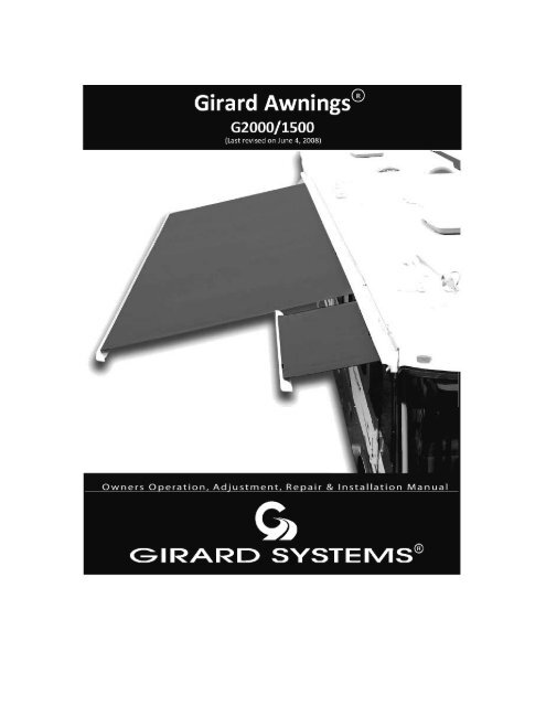
--------------- GIRARD<br />
SYSTEMs"<br />
®<br />
GIRARD SYSTEMS<br />
G-2000Automatic Lateral Arm Awning System<br />
G1500 Door Lateral Arm Awning System<br />
OWNERS OPERATION AND CARE<br />
MANUAL<br />
<strong>Girard</strong> <strong>Systems</strong> © 2005 5
IMPORTANT OPERATION REMINDERS<br />
1. Confirm that sufficient 110 volt power is supplied to awning system for correct functioning<br />
ofall component parts (i.e. - controller, anemometer, awning motor, etc.) Be sure either:<br />
a. Inverter is on;<br />
b. Generatoris functioning; or,<br />
c. Vehicle is connectedto shore power.<br />
2. Turn on vehicle power <strong>and</strong>!orturn circuit breakers to "ON."<br />
Make note thatthe ignition to the coach is OFF.<br />
A. OPENING/EXTENDING AWNING<br />
1. Using Remote Control (See Fig. 1)<br />
a. To extend awning, push down button (arrow) once. (When fully extended, awning<br />
motor will turn offautomatically. Ifnot, refer to ''Adjusting Motor Limit Switches")<br />
b. To retract awning, push up button (arrow) once. (When fully retracted, awning<br />
motor will turn offautomatically. Ifnot refer to "Adjusting Motor Limit Switches")<br />
c. Push middle button (stop) during either extend or retract mode to stop awning at any<br />
desired position. The middle (stop) button can also be used to change (reverse) mode from<br />
extend to retract or from retract to extend.<br />
2. Using Wall Mount Rocker or Paddle Switch (See Fig. 1)<br />
a. To extend awning, push down on rocker or paddle switch. (When fully extended,<br />
awning motor will turn offautomatically. Ifnot, refer to "Adjusting MotorLimit Switches")<br />
b. To retract awning, push up on rocker or paddle switch. (When fully retracted awning<br />
motor will turn offautomatically. Ifnot refer to ''Adjusting Motor Limit Switches")<br />
c. To stop awning at anytime during extension or retraction, press opposite endof<br />
switch <strong>and</strong> awning will stop its progress.<br />
3. Motor<br />
a. The Motor supplied with your <strong>Girard</strong> G-2000 Awning <strong>and</strong>!or G-1500 Awning is a<br />
high torque!low RPM motorwhich has been carefully selcted for reliability <strong>and</strong> application<br />
compatibility. It is designed for intermittent use with a rating ofsix (6) minutes per hour. If<br />
the motor's run-time exceeds this time period, a built-in circuit breaker will disable motor<br />
from operation. Generally, this condition will occur only during excessive periods ofusage!<br />
6 <strong>Girard</strong> <strong>Systems</strong> © 2005
--------------- GIRARD<br />
SYSTEMs"<br />
awning adjustment. Ifbuilt-in motor shut offdoes occur, allow sufficient time for motor to<br />
reset (up to one hour depending on outside temperatures). The manual override feature can<br />
be used during this period.<br />
b. The Wind Sensor V Controller <strong>and</strong>the Anemometerworktogetherto continuously<br />
monitor the wind speed around your awning at any given moment. Ifthe actualwind speed<br />
becomes greater than the wind speed setting ofyour controller, a two-second delay occurs<br />
<strong>and</strong> a signal is sent to the awning motor to retract the awning. (The awningwill remain in<br />
the retracted position until such time that it is again extended by pressing the down<br />
button on switch.)<br />
G-2OOO Rocker SwItch<br />
G-1500 Paddle SwItch<br />
wall Mounl<br />
(Rocker) Switch<br />
Face Plate<br />
Brown<br />
Wall Mount<br />
(Paddle) Switch<br />
Face Plate<br />
Four Channel RTS Remote SwItch<br />
'~<br />
j<br />
IZI<br />
0' " ..j<br />
fZ)I /"<br />
j)':!)<br />
"'0'<br />
IZI<br />
~, r<br />
Wall Mount<br />
(4 buttonl4 LED) Remote Switch<br />
Face Plate<br />
FIGURE 1<br />
WAlL MOUNT (ROCKER/PADDLE) SWITCH<br />
<strong>Girard</strong> <strong>Systems</strong> © 2005<br />
7
B. REMOTE CONTROL<br />
(Programming)<br />
1. Press the Programming Button (PROG) ofthe receiverlocatedin wind sensor control<br />
box (lower right corner) until LED lights. This indicates that for one (1) minute the<br />
receiver is readyto receive the address ofthe transmitter. Mter this time,the LED<br />
goes out.<br />
2. Press the Programming Button on the backofthe transmitter (Fig. 2) with a ballpoint<br />
pen until the receiver's LED blinks. The address ofthe transmitter is instantly<br />
memorized <strong>and</strong>the receiver automatically ends the programming mode.<br />
3. To add or delete channels in receiver memory, please refer to instruction guide in<br />
remote control packaging.<br />
4. To change batteryon remote controltransmitter (See repair <strong>and</strong> replace section):<br />
Screw Anchors<br />
~..<br />
w'~<br />
Wood Screw<br />
......~<br />
IJ+----+-- Programming<br />
Button<br />
RTS Receiver<br />
LED Light(4)<br />
FIGURE 2<br />
REMOTE CONTROL TRANSMITTER<br />
8<br />
<strong>Girard</strong> <strong>Systems</strong> © 2005
--------------- GIRARD<br />
CARE<br />
SYSTEMs"<br />
C. INSTRUCTIONS FOR CARE AND CLEANING OF FABRIC<br />
To ensure longevity offabric quality it is highly advisable to maintain a regular regiment ofsimplybrushing<br />
offdaily debris <strong>and</strong> dirt from fabric. To clean the awning rinse with water. In a separate bucket mix a mild<br />
soap in water (natural soaps are best) with a clean brush dunkinto the bucket <strong>and</strong> clean the awning with<br />
sweeping motions; rinse thoroughlyto remove soap. Ifyou decide to use a liquid detergent you will need to<br />
reaplya water repellent treatment, such as 303 Hi-Tech Fabric Guard or similar product. Fabric is made<br />
from 100% acrylic fiber. (IfFabric is non-acrylic-Soltis material use liquid detergent <strong>and</strong>water) Let<br />
fabric air dry. Ifyou need to store your fabric, keep in a dry ventilated area.<br />
DO NOT SUBJECTAWNING FABRICTO EXCESSIVE HEAT as the fabric will shrink.<br />
DO NOT STEAM PRESS OR DRYIN ELECTRIC OR GAS DRYERS, but allow to air dry.<br />
STAIN SOLUTIONS FOR:<br />
Fruit Stain-liquid detergent/ammonia 3-6% water<br />
Grease(car)-volatile solvent(acetone)<br />
Iron Rust-oxalic or citric acids, water<br />
Mildew-1/2 cup ofbleach <strong>and</strong> 1/4 cup ofnatural soap per gallon ofwater<br />
Oil-solvent (acetone)<br />
Paint (latex) wet-liquid detergent,water<br />
Paint (latex) dry-Paint, oil or grease remover<br />
Paint (oil or laquer)-paint,oil grease remover<br />
Tree sap-turpentine,liquid detergent<br />
REPAIR AND REPLACE<br />
D. RTS REMOTE SWITCH BATTERY REPLACEMENT<br />
1) Remove RTS Remote Switch following the reverse ofthe installation.<br />
2) Hold RTS Remote Switch bythe front allowing easy access to the rear.<br />
3) Using small phillips screwdriver remove the two screws from the recessed cavities in either corner.<br />
4) Carefully remove back plate bylifting directly away from front plate (See Figure 3).<br />
5) Use st<strong>and</strong>ard screwdriver or similar tool to slide old battery from cradle.<br />
6) Insert new batterywith fingers, <strong>and</strong> attach backplate using reverse ofthe removal.<br />
7) Reinstall RTS Remote Switch <strong>and</strong> recalibrate ifneeded.<br />
<strong>Girard</strong> <strong>Systems</strong> © 2005 9
FIGURE 3<br />
RTS REMOTE SWITCH BATTERY REPLACEMENT<br />
E. REMOTE CONTROL BATTERY REPLACEMENT<br />
To change batteryon remote control transmitter (Fig. 4):<br />
1) Remove backcoverwith screwdriver.<br />
2) Slide batteryout bypushingwith screwdriver.<br />
3) Insert new battery<strong>and</strong> close backcover.<br />
Phillips<br />
Screw<br />
Battery<br />
FIGURE 4<br />
REMOTE CONTROL TRANSMITTER BATTERY REPLACEMENT<br />
10<br />
<strong>Girard</strong> <strong>Systems</strong> © 2005
®<br />
GIRARD SYSTEMS<br />
G-2000Automatic Lateral Arm Awning System<br />
G1500 Door LateralArm Awning System<br />
ADJUSTMENT/REPAIR<br />
MANUAL<br />
WARNING: Improperinstallation, adjustment, alteration, service, ormaintenance can cause<br />
injuryor propertydamage. Carefully read manualbefore beginninginstallation. Instructions<br />
subjectto change withoutpriornotice.<br />
San Clemente CA . Tel: (800) 382-8442 . Fax: (949) 587-9680
GIRARD SYSTEMS<br />
G-2000/G-1500 ADJUSTMENT AND REPAIR<br />
F. FINAL ADJUSTMENTS<br />
ADJUSTING MOTOR LIMIT SWITCHES<br />
Tools required<br />
• Blackplastic key providedwith awning, or 4mm (5/32") Allen wrench<br />
PROCEDURE<br />
The limit switches are adjusted at the factory prior to shipment. The awning motor is set to stop<br />
at the exact moment the awning box closes. (Ifusing an ACL current-limiting device, you will<br />
have to turn the IN limit three plus (+) revolutions past the awning's closing point. This only<br />
applies to the IN limit.) The awning motor is also set to stop at the exact moment that,while<br />
opening, the arms lockinto the extended position.<br />
Always checkthe motor rotational limits after installation to assure that the awning opens <strong>and</strong><br />
closes correctly. Additionally, awning fabric can stretch, requiring simple adjustments.<br />
VERY IMPORTANT: Extreme care must be taken when setting the IN limits ofthe motor to ensure<br />
thatthe motor turns offat exactlythe same time as the awning box closes; ifnot, the motor will<br />
continue to run as it has not reached its limit. This condition,ifnot corrected,will substantially<br />
reduce motor life. Turn the awning switch OFFwhen awning is fully retracted. (This applies<br />
onlyto coaches older than 2000 models, unless theyare compatible.)<br />
Ifadjustments are required, please follow these instructions:<br />
1. The DMI (manual override) motor has limit settings for both OUT (extension) <strong>and</strong>IN<br />
(retraction).<br />
12 <strong>Girard</strong> <strong>Systems</strong> © 2005
--------------- GIRARD<br />
SYSTEMs"<br />
2. Adjust the limit switches with the black plastic key (provided) or a 4mm Allen wrench.<br />
3. Extendthe awning a few feet <strong>and</strong>locate the cylindrical awning motor mountedinside the<br />
awning roller tube (st<strong>and</strong>ardinstallation is atthe right/front endofthe awning). The limit<br />
switches are mounted on the aluminum (silver) casing atthe exposed end ofthe motor. At<br />
the limit switches are two black directional arrows, eachwith a plus (+) <strong>and</strong> a minus (-) sign.<br />
The actual limit switch is the recessed hole next to the corresponding arrow.<br />
4. Adjustlimits according to the directional arrows (see Fig. 5 callout). A 1/4 turn represents<br />
approximately 1" ofawning movement. Never set outward limits so that fabric is slack after<br />
full arm extension. Adjust limit switches until the motor stops at the exact time that the<br />
arms lockinto position.<br />
The diagram belowrefers only to motors with aluminum (silver) casings.<br />
Note:<br />
If the motor is mounted on<br />
the left end of the awning,<br />
the functions of the limit<br />
switches will be reversed.<br />
To adjust OUT limits:<br />
Use the outermost switch.<br />
(+) Extends More; (-) Extends LessA<br />
To adjust IN limits:<br />
Use the innermost switch.<br />
(+) Closes More; (-) Closes Less<br />
FIGURE 5<br />
ADJUSTIHG MOTOR LIMIT SWITCHES<br />
<strong>Girard</strong> <strong>Systems</strong> © 2005<br />
13
ADJUSTING MOTOR LIMIT SWITCHES<br />
(CONTINUED)<br />
PROCEDURE<br />
Mter a motor has been replaced, the limit switches which control the awning's inward<br />
<strong>and</strong> outward stopping points must be reset. The IN switch must be set so that the<br />
awning motor stops at the exact moment the awning box closes. Likewise, the OUT<br />
limit must be set to stop at the exact moment that, while opening, the arms lockinto<br />
position. With a new motor the limit switches are set at mid-point; the awning will stop<br />
with the OUT limit at approximately half-extension, <strong>and</strong>the IN limitwill be set past<br />
where the awning should normally close.<br />
For a right-h<strong>and</strong> motorinstallation (st<strong>and</strong>ard), the OUTlimit switch is the outermost<br />
hole, <strong>and</strong>the IN limit switch is the innermost hole. For a left-h<strong>and</strong>installation, these<br />
switch locations (holes) are opposite (reversed). See diagram on page 13 for reference.<br />
SETTING OUT (EXTEND) LIMITS<br />
1. Extendthe awning until the motor stops.<br />
2. Locate the motor limit switches mountedinside the silver casing at the exposed<br />
end ofthe motor. Beside each switch is a directional arrow with a plus (+) <strong>and</strong> a<br />
minus (-) sign. The actual limit switch is the recessed hole next to the<br />
corresponding arrow.<br />
SETTING IN (RETRACT) LIMITS<br />
1.<br />
2.<br />
3.<br />
4.<br />
5.<br />
6.<br />
Place the awning in the IN position <strong>and</strong> allow the awning to roll up to about 6" of<br />
being fully closed. Place the switch in the STOP position.<br />
Locate the IN limit switch. Turn the switch in the (-) direction about twenty<br />
(20) turns.<br />
Place awning switch in the OUT position <strong>and</strong> open the awning a few inches.<br />
Reverse the switch direction to close the awning. (This is to ensure that the IN<br />
limit switch stops the awning before the awning is completelyclosed. Ifnot,<br />
continue adjusting the IN limit switch in the (-) direction until the awning stops<br />
before it is closed.)<br />
Once it is correctly adjusted, place the awning switch in the IN position <strong>and</strong> turn<br />
the IN limit switch in the (+) direction. The awning will "follow" as you turn the<br />
switch. Continue until the awning boxis approximately 3" from closing.<br />
The final adjustment requires estimating the amount ofawning closure per<br />
14<br />
<strong>Girard</strong> <strong>Systems</strong> © 2005
--------------- GIRARD<br />
SYSTEMs"<br />
switch rotational distance. (A 1/4turn represents approximately 1" ofawning movement.)<br />
Turn the switch the estimated amount, keeping your h<strong>and</strong> away from the box as the awning<br />
closes. Make sure the motor does not continue to run or hum after the boxis closed; ifit<br />
does, open the awning a few inches <strong>and</strong> backthe switch up in the (-) direction. Repeat this<br />
procedure until the motor turns offat the exact moment the awning box closes.<br />
TESTING ANEMOMETER<br />
1. Partiallyextend awning.<br />
2. Blow or spin anemometer cups to check retraction. Awningmustretract; ifnot, check<br />
motor connections for proper polarity.<br />
ADJUSTING PITCH ANGLE ANGLE<br />
Drop the awning 5"to allow lor rain runoff.<br />
For adjustment, see Figures 21 <strong>and</strong> 22.<br />
Factory pre-set pitch angle<br />
FIGURE G<br />
RESETTING FACTORY PRE-SET PITCH ANGLE<br />
The awning comes factory pre-set with a pitch angle ofapproximately 20 0<br />
(Fig 6), the minimum<br />
angle recommended for proper rain runoff To increase this angle, loosen the pivot boltlocated on<br />
the outside upperjoint ofeach arm using a 3/4" or 19mmwrench. Use the same wrench to lower<br />
or raise the pitch angle byturning the adjustment bolt clockwise to lower, counterclockwise to raise.<br />
(See Figs. 7 <strong>and</strong> 8.)<br />
<strong>Girard</strong> <strong>Systems</strong> © 2005 15
Loosen front bolt<br />
Pivot bolt<br />
/<br />
~,?-Q~~"l r Screw<br />
FIGURE 7<br />
LOOSEN PIVOT BOLT<br />
HEIGHT ADJUSTMENT OF ARMS<br />
Tools Required:<br />
-0 19mm (3/4") Open end wrench<br />
-0 10mm (3/8") Open end wrench<br />
This adjustment may be required if, as the awning Lead Rail closes into the awning casing, the 'elbow' of<br />
one ofthe arms is hanging downward, hitting the bottom ofthe casing. This adjustment is usually<br />
required after an arm replacement<br />
1) Open the awning about 18 inches.<br />
2) Atthe selected arm, loosen the (2) locknuts located atthe side ofthe upper arm connection<br />
using a 19mm (3/4") open-end wrench.<br />
3) See exploded view <strong>and</strong> Figure 7. Locate the smaller adjustment bolt located directly under<br />
the rearlocknutthatwasjustloosened. Place a 10mm (3/8") open-endwrench around the<br />
bolt head, <strong>and</strong> rotate the wrench in a TIGHTEN (clockwise direction) to raise the arm.<br />
Slight rotation is all that is necessary; Likewise, LOOSENING (counter clockwise direction)<br />
the bolt will lower the arm. As this adjustment is being performed, keep in mindthat after<br />
re-tightening the locknuts, the arm will rise slightly higher.<br />
4) Tighten the (2) locknuts located on the side ofthe arm connection.<br />
5) Close the awning completely, <strong>and</strong> check for proper fit.<br />
16 <strong>Girard</strong> <strong>Systems</strong> © 2005
--------------- GIRARD<br />
SYSTEMs"<br />
Adjustment Bolt<br />
FIGURE 8<br />
ADJUSTMENT BOLT<br />
ADJUSTING LEAD RAIL<br />
Pitch Angle Screw<br />
0/<br />
FIGURE 9<br />
PITCH OF LEAD RAIL WHEN CLOSED<br />
<strong>Girard</strong> <strong>Systems</strong> © 2005 17
The awning lead rail comes factory pre-set with a pitch angle of+/- 3°. This angle allows the lead rail<br />
to fit snuglyinto the main housing cover <strong>and</strong> the back housing, making a weather-resistant seal for<br />
travel.<br />
To increase or decrease the angle, insert a 5mm Allen wrench into the top pitch angle screw. Turn<br />
clockwise to increase the pitch, counterclockwise to decrease the pitch. (Fig 9 & 10)<br />
Lead Rail<br />
Fabric Set Screw<br />
Pitch Angle Screw<br />
Horizontal<br />
Lead Rail Adjustment Screw<br />
FIGURE 10<br />
ADJUSTMENT OF LEAD RAIL CONNECTOR<br />
To adjust the lead rail connector, allow itto align itself. This is done byopening awning about two<br />
(2') feet. Remove fabric set screw on both sides. Then loosen horizontal lead rail adjustment screws.<br />
Align all elbows to ensure proper closing. Next, moderatelytighten hori=ntallead rail adjustment<br />
screws <strong>and</strong> close awning. Ifawning does not close correctly, open awning two (2") inches <strong>and</strong><br />
moderately hit end oflead rail which is binding. Then ensure that lead rail is even on both sides.<br />
Close <strong>and</strong> then reopen awning <strong>and</strong> tighten hori=ntallead rail adjustment screw <strong>and</strong> re-insert fabric<br />
set screw.<br />
Note: Arms will reset once awning is completely enclosed.<br />
18 <strong>Girard</strong> <strong>Systems</strong> © 2005
--------------- GIRARD<br />
SYSTEMs"<br />
G. ANEMOMETER DISASSEMBLY<br />
(NOTE: This is only for new style anemometer)<br />
1) Remove Anemometer from aluminum base following reverse ofinstallation instructions.<br />
2) Holding cylindrical plastic base ofanemometer use fingers to holdwind cups steady.<br />
3) Use 7/32 socketwrench or open endwrench to remove plastic nut from top ofanemometer.<br />
4) Using gentle force pullwind cup assembly straight up offofanemometer base (See Figure 11).<br />
CAUTION: be careful not to bend or damage brass spindle rod as this would render the<br />
anemometer useless.<br />
5) Reassemble anemometer in reverse order using newwind cup assemblyin conjunction with old<br />
plastic anemometer base.<br />
6) Reinstall anemometerto aluminum base.<br />
7) Recalibrate anemometer using steps described in the installation instructions.<br />
Use 7132-""'ket~<br />
,<br />
Wind Cup Assembly-_~<br />
Brass Spindle Rod --_~I<br />
Aluminum Base<br />
FIGURE 11<br />
ANEMOMETER DISASSEMBLY<br />
H. INSTRUCTIONS FOR REPLACING A MOTOR<br />
<strong>Procedures</strong> mayvary from one vehicle to the next, for the removal <strong>and</strong> replacement ofmotors on the<br />
G-2000 awning. This variation, in part,is a result ofdifferent factory installation methods <strong>and</strong><br />
preferences on different vehicles. It mayalso be a result ofthe placement ofthe awning on the<br />
vehicle, i.e. accessibilityofthe motor. This variation primarilyaffects the initial accessing ofthe<br />
motor. Subsequent replacement operations are basicallythe same. These instructions address the<br />
'accessing the motor' as a separate categoryfor clarification purposes. Additionally, variations in the<br />
motor style exist. The procedures are intendedto be universal <strong>and</strong> inclusive ofall motor types <strong>and</strong><br />
installations.<br />
<strong>Girard</strong> <strong>Systems</strong> © 2005 19
SECTION I ACCESSING THE MOTOR<br />
Beavermotorcoaches: Awning is recessed into vehicle sidewall. Awning end plate is not<br />
immediatelyaccessible:<br />
1) Locate the awning mounting bolts. There will be (3) sets of(6) ofthese, which secure the<br />
awning brackets, through to the inside ofthe vehicle. Theyare usually found inside the<br />
upper cabinets <strong>and</strong> are located directly behindthe connection point ofthe awning arms.<br />
Onlythe forward set ofbolts needto be accessed.<br />
2) Loosen each bolt from the inside byremoving each respective nut. Loosen the nuts only<br />
from the forward mounting bracket.<br />
3) Using a sharp utility knife, <strong>and</strong> from outside to the vehicle, cut away 3 feet ofthe Silicon<br />
adhesive around the top, side, <strong>and</strong> bottom edges ofthe awning casing. Do this from the front<br />
ofthe awning only.<br />
4) Carefullypull the right front section ofthe awning casing away from the vehicle to point<br />
where the entire awning end cap is accessible. Do this byeither extending the awning all the<br />
way, <strong>and</strong> pulling down gentlyon the lead rail, this will pryawning out ofthe wall. Place a<br />
solid object (large flat screw driver, flat file, etc.) behind the awning casing, in front ofthe<br />
recess area, to holdthe awning away.<br />
5) Proceedwith section II, removing the old motor.<br />
Safari motor coaches: Awning is recessed into vehicle sidewall. Awning endplate is accessible<br />
through a hidden recess.<br />
1) Locate the 2"x8" plate mounted over hidden recess directlypastthe front/right h<strong>and</strong> edge of<br />
the awning. Remove the plate bydrilling outthe (3) pop rivets that secure itto the vehicle<br />
sidewall.<br />
2) Proceed with Section II, Removingthe OldMotor.<br />
Surface mount installations (all othermanufactures): Awning is NOT recessed into vehicle<br />
sidewall. Awning endplate is easily accessible. SectionII. Removingthe OldMotor.<br />
1) Open the awning about 3 ft. Ifthe awning is not equippedwith a manual crank override<br />
<strong>and</strong> the awning cannot be opened, please see paragraph III below.<br />
2) Before replacing the motor, open the awning partially<strong>and</strong>put a mark on fabric guide #4<br />
(refer to diagram on page 62) on the motor side, indication the endofthe roller tube. This<br />
guide will have to be short endto the same length as the roller tube to fit the new motor.<br />
This can be done with a pair oftin snips.<br />
3) Fullyextend awning bymanuallycranking the awning out until the fabric starts to sag. With<br />
the awning fully extended have another person pull down on the lead rail slightly until you<br />
are able to put something behind the awning to holdit offthe wall. Make sure there are no<br />
nuts on the 6 bolts that hold the awning to the wall.<br />
4) Tape or strap each arm, about 1 ft.in from the 'elbow', such thatthe arms are lockedinto<br />
their position. These arms must be securely fixed against their own spring tension, such that<br />
the awning is prevented from opening further when the motor is removed. "Use this method<br />
ifawning can not be fully extended".<br />
20 <strong>Girard</strong> <strong>Systems</strong> © 2005
--------------- GIRARD<br />
SYSTEMs"<br />
5) Remove the right h<strong>and</strong>/front awning end plate byremoving the (3) Phillips screw, which<br />
secure it to the awning casing.(Figure 12)<br />
6) Remove both motor bolts (Figure 13,) which fasten the motorto the motor end bracket<br />
Take note <strong>and</strong> markthe slots from which the boltwere removed.<br />
7) Loosen the small bolt bya couple ofturns, which secures the motor end bracket to its<br />
holding bracket. Do not over-loosen or attempt to remove this bolt. Slide the motor end<br />
bracket away from its holding bracket <strong>and</strong> remove.<br />
8) Enter into the vehicle, <strong>and</strong>locate the termination point ofthe motor cord. This pointwill<br />
be either inside junction box used for the awning switch, orwill be inside the electronic<br />
box. Either can probablybe found inside ofan upper cabinet. The motor cord ca be<br />
identified as the WHITE cord bearing (4) wires. Take note ofthe point's from which<br />
each motor wire disconnects. See also wiring diagram. Disconnect complete motor cord.<br />
9) Tape a long 'pig tale' extension to the motor cord (using string, rope, small wire, etc.) such<br />
thatwhen the cordis pulledthrough, its routing is not lost. Exit vehicle <strong>and</strong> pull motor<br />
cord completelythrough wall.<br />
10) Carefullypull old motor out ofawning roller tube. (Figure 13) Pull motor cord out ofhole<br />
in backofawning casing, <strong>and</strong> disconnect motor cord form the 'pig tail'.<br />
11) Locate the roller tube.<br />
After Removal of<br />
(3)Screw For End Plate<br />
(2) Bolt For Motor Mount<br />
Roller Support Bracket<br />
Sl1de Motor set out to the rIght<br />
Remove<br />
Bolt For Motor Moum<br />
Rom....<br />
Roller Tube Support Bracket<br />
r.,,~<br />
l.a:~~<br />
~ "''''''~ '<br />
Motor Sst<br />
. ,<br />
Some piscss not shawn for clarity<br />
Roller Tube<br />
"-,,- Roller Tube<br />
"'-.....j Support Bracket<br />
Bolt Foe<br />
Motor Mount<br />
Tube Support Bracket<br />
(DO NaT REMOVE)<br />
~<br />
'_'-'<br />
'":C'<br />
.(;GlldlngAngle<br />
.... " At Motor<br />
Screw For<br />
Main Housing<br />
End Plate<br />
'1"<br />
d Plate<br />
FIGURE 12<br />
END PLATE REMOVAL<br />
FIGURE 13<br />
REMOVING OLD MOTOR<br />
Section IIa Removing the old motor ifthe awning cannot be opened <strong>and</strong> has no manual<br />
override.<br />
Note: (3) people <strong>and</strong> (3) ladders will be required to perform the first portion ofthis procedure.<br />
1) remove the right h<strong>and</strong>/front awning endplate <strong>and</strong>lead rail end plate byremoving the (5)<br />
Phillips screws, which secure them to the awning casing.<br />
<strong>Girard</strong> <strong>Systems</strong> © 2005 21
2) Place one person in front ofthe rear portion ofthe awning. Place a second person in<br />
front ofthe front potion ofthe awning. The third person will perform the following:<br />
Remove both motor bolts which fasten the motor to the motor endbracket (Figure 13).<br />
Take note <strong>and</strong> markthe slots from which the bolts were removed. The awning will now<br />
begin to extend.The first <strong>and</strong> second persons should allow the awning to extend about 3<br />
ft. At this point, each arm must be taped. Or strapped, about 1 ft. in from the 'elbow',<br />
such that the arms are locked into their position. These arms must be securely fixed<br />
against their own spring tension, suchthat the awning is prevented from opening<br />
further.<br />
3) Proceedwith step #3 ofSection II. Removing the Motor.<br />
SECTION III. INSTALLING THE NEW MOTOR<br />
Note: Ifthe new motor that is being installedis ofa different type ofstyle from that being<br />
replaced, please review Section IV, Motor Variations <strong>and</strong> Section V, Conversion to Manual<br />
Override before proceedingwith this section.<br />
1) With the new motorin h<strong>and</strong>, align the notch in the black drive-diskat the far endof<br />
motorwith the indentation in the awning roller tube. Slide motor all the wayin.<br />
likewise, turn the black diskat the front ofthe motor such that its notch also lines up<br />
with the indentation in the roller tube. (See Figure 13.)<br />
2) Feedthe motor cord completelythrough the hole in the backofthe awning casing. Tape<br />
this cordto the 'pig tale' that was previouslybrought through the cord entrance.<br />
3) Ensure thatthe awning roller tube is still seated, <strong>and</strong>lodgedinto its endbracket atthe<br />
far end ofthe awning.<br />
4) Rotate the motor <strong>and</strong> roller tube assembly such that the motor limit switches are<br />
accessible <strong>and</strong> at an approximate 6:00 o'clock position (from right end viewing) <strong>and</strong> that<br />
the manual override mechanism has proper downward clearance.<br />
5) Slide the motor endbracketbackin toe awning casing <strong>and</strong> over the 'dove tale' connection<br />
ofits holding bracket. Tighten securelythe small bolt that secures the two brackets<br />
together.<br />
6) Adjust the roller tube! motor assembly such that the threaded holes in the metal bracket<br />
ofthe motor line up with the (2) marked hole locations ofthe motor end bracket.<br />
NOTE: Do notuse centerhole ofmotorcasingto pry, to aligne, to replace motorbolts.<br />
Thiswill cause damage to limit switches. Onlypryfrom outer partofmotorcasing.<br />
7) Insert the (2) motor bolts through the end bracket <strong>and</strong> through the threaded plate ofthe<br />
motor. Tighten bolts securely.<br />
8) Replace awning end cap.<br />
9) From inside the vehicle, pull the 'pig tale'thatwas fastened to the endofthe motor cord,<br />
<strong>and</strong> feed the new motor cord all the wayin.<br />
10) Wire the new motor cord as previously noted, <strong>and</strong>!or refer to either the wiring diagram<br />
(for wind sensor operation) or the switch-wiring diagram, for direct switching to awing.<br />
11) Remove the taping ortrapping forms the arms that was placed to prevent movement.<br />
The awning will remain in that position.<br />
22<br />
<strong>Girard</strong> <strong>Systems</strong> © 2005
--------------- GIRARD<br />
SYSTEMs"<br />
12) Test for proper functioning ofthe new motor connections byoperating the awning switch or<br />
the wind sensor switch. The upward arrows retracts. The downward arrows extend.<br />
13) Blow or spin anemometer cups to check for retraction (Important! Awningmustretract- if<br />
not, check motor connections for proper polarity.)<br />
14) After a motor has been replaced, it is extremelyimportant that the motorlimit switches be<br />
adjusted such thatthe motor turns offat the exact point (onlyifACL current limiting device<br />
is not compatible) that the awning box closes. Likewise, the motor should turn offat the<br />
exact point the awning arms reach full extension <strong>and</strong>'click' into place. Please see section<br />
entitled Adjusting Motor Limits Switches.<br />
SECTION IV. CONVERSION TO MANUAL OVERRIDE<br />
Ifa non-manual override motor is being replaced with a manual override motor, follow all<br />
procedures as outlinedin:<br />
Section I, Accessing the Motor<br />
Section II, Removing the OldMotor<br />
Then - Before beginningSection III, Installing the NewMotor, please complete the following:<br />
1) Locate the fabric guide rail on the inside front ofthe awning casing, <strong>and</strong> slide out to the<br />
right, away form casing, 3 to 4 inches.<br />
2) Using a hacksaw, cut off2 inches ofthis fabric guide rail ifthe awning is surface mounted.<br />
Use tin snips to cut offthe 2 inches ofthe fabric guide rail ifthe awning is recessed.<br />
3) Slide the fabric guide rail back in completely.<br />
4) Proceedwith step #1, ofSection III, Installing the NewMotor.<br />
AndThen:<br />
After installing the new motor <strong>and</strong> completing steps #1 through #4, <strong>and</strong> as you are testing the motor<br />
<strong>and</strong>wiring installation in step #12, complete the following:<br />
1) Stop the awning lead rail just before the box closes.<br />
2) The awning lead rail must have a clearance notch thatwill clear the manual override<br />
mechanism, as the lead rail closes into the awning casing.<br />
3) Ifthis hole is not present, proceed in cutting a hole 1-3/4" wide x 2" deep into the lead rail.<br />
A plastic sleeve is available to cover the edges to this hole <strong>and</strong> can be ordered under PIN<br />
1500275-54<br />
4) Proceed with steps #12 <strong>and</strong> #13.<br />
IMPORTANT NOTE: CHECK FOR CORRECT FUNCIONS BY SPINNINGTHE<br />
ANEMOMETER- AWNING MUST RETRACT WHEN ANEMOMETER IS SPUN!<br />
<strong>Girard</strong> <strong>Systems</strong> © 2005 23
I. FABRIC REPLACEMENT<br />
RECESSED AWNINGS:<br />
This fabric changing procedure is recommended for use on G-2000 Awnings in which the<br />
awning has been 'recessed' into the vehicle sidewall. This is typical with both'Beaver' <strong>and</strong>'Safari'<br />
Motor Coach installations. Ifthe awning has not been recessed <strong>and</strong> has been 'surface' or'flush'<br />
mounted onto the vehicle side, please see 'Fabric Replacement Method#2, Surface mounted<br />
awnings.' In either case, the old awning fabric can be removed without the need to remove the<br />
complete awning, or the awning roller tube. All awning hardware will remain in position.<br />
NOTE: this procedure requires the use ofthe awning manual crank. Ifno manual crankis<br />
available, the motor limit switches must be used to create the settings. Ifthis case, refer to<br />
'AdjustingMotor Limit Switches".<br />
REMOVING THE OLD FABRIC:<br />
1) Open the awning fully until the arms 'click'into place. Using the manual crank, (use the<br />
motor limit switches <strong>and</strong> adjust, ifno crankis available) continue to rotate the roller tube<br />
until all the fabric is unrolled <strong>and</strong>the 'C' groove ofthe roller tube is accessible.<br />
2) Remove the (4) four fabric set screws (two arelocatedon thelead rail <strong>and</strong>two arelocatedon<br />
the roller tube. see Figure 14 & 15)<br />
3) Remove the left h<strong>and</strong>lead rail end cap. Shiftthe fabric from the roller tube 'C' groove by<br />
sliding it along to the left h<strong>and</strong> endofthe tube. At this point the white poly rope should be<br />
accessible from the endofthe fabric <strong>and</strong> roller tube.<br />
4) Using a screwdriver, bend the Poly rope down <strong>and</strong> outward such that it can be gripped with<br />
a pair ofpliers. Pull the poly rope completely out ofthe roller tube.<br />
5) The remaining fabric will now be free <strong>and</strong> fall from the roller tube.<br />
6) Slide the old fabric out ofthe left h<strong>and</strong> side ofthe lead rail.<br />
7) Preserve the Poly rope thatwas removed from the fabric at the roller tube.<br />
Poly Rope<br />
Poly Rope<br />
Main Housing<br />
End Plate<br />
Roller Tube<br />
Fabric Set scr~:<br />
!<br />
Some pieces not shawn for clarity<br />
FIGURE 14<br />
REMOVAL OF END PLATE (LFEFT SIDE)<br />
FIGURE 15<br />
REMOVAL OF FACE PLATE AND POLY ROPE<br />
24<br />
<strong>Girard</strong> <strong>Systems</strong> © 2005
--------------- GIRARD<br />
INSTALATION OF NEW FABRIC<br />
SYSTEMs"<br />
IMPORTANT NOTE: Replacement fabrics are shipped in a rolled condition. The front edge ofthe<br />
fabric will be marked 'lead rail end-up', <strong>and</strong> will be the leadingedge ofthe roll as you receive it. The<br />
hems will always face downward as the fabric is installed. The other end ofthis fabric will have<br />
mounted, inside ofthe hem, a small Poly rope. This end will be mounted into the roller tube. The Poly<br />
rope that was removed from the old fabric at the roller tube will get used for this installation.<br />
1) Tape the sharp edges ofthe 'C' channel (fabric channel) ofthelead rail such thatthe fabric will<br />
slide <strong>and</strong> enter freely without snagging or tearing.<br />
2) Slide the white Poly rope, thatwas removed from the old fabric, completelyinto the open, front<br />
hem ofthe new fabric (marked Lead Rail). The second Poly rope form the old fabric will not be<br />
used in this installation).<br />
3) The new fabric will need to be unrolled <strong>and</strong>insertedinto both the lead rail, <strong>and</strong> the roller tube at<br />
the same time. This is done in small even increments about 1-2 feet per pull. You will have to<br />
manipulate the fabric into the roller tube, as itwill be a tight squeeze to fit the fabric in because<br />
the limited space toworkwith. Insert carefully as to not snag or tear fabric. Ensure that the<br />
seams are facing downward. Continue until entire length offabric has been fed into both roller<br />
tube <strong>and</strong> lead rail.<br />
4) Slide the fabric back <strong>and</strong> forth inside the roller tube to assure the entire length ofhem has been<br />
properlyinserted. Center the fabric on the roller tube, <strong>and</strong> square up fabric assembly at lead rail,<br />
i.e., remove wrinkles. Insert selftaping screws on both ends ofthe fabric into roller tube. The<br />
fabric will self-center on the leader rail.<br />
5) Slowly begin to roll the fabric up, onto the roller tube, using the manual crank. (The motor limit<br />
switches will have to be used, <strong>and</strong> adjustedifno manual crank is available). Roll the fabric from<br />
the bottom ofthe roller tube. (See Figure 14)<br />
6) Using two people, carefully stretch the fabric from endto end during the first few revolutions of<br />
the roller tube, to assure the fabric is rolling straight <strong>and</strong> true. Continue to slowly roll the fabric<br />
onto the tube until the fabric is taught <strong>and</strong> in its 'full extension' mode against the locked, fully<br />
extended arms. Continue to roll the fabric in, this time using the awning switch <strong>and</strong> motor.<br />
Watch carefully to assure the fabric rolls straight, <strong>and</strong> close the awning completely.<br />
7) Once again, open awning about 18 inches. Pull the leading edge ifthe fabric taught, from both<br />
ends, <strong>and</strong> replace both fabric set screws. Note: These screws should be located No Further than<br />
3;,\" from the edge ofthe fabric. Re-drill fabric set screw holes. Ifnecessarywith a 1/8" dia. drill<br />
bit, to maintain this distance.<br />
8) Replacelead rail end cap.<br />
9) After a fabric replacement,it maybe necessary to make minor adjustments to the motor limits<br />
switches to assure that the awning motor stops exactlywhen the box closes (unless using ACL<br />
currant limiting device. Likewise, it is important that the awning motor stops exactlywhen the<br />
awning is extending <strong>and</strong> the arms 'snap' into their full extension position. Please see 'Adjusting<br />
Motor Limit Switches'<br />
Important Note: The high torque motor which is supplied with the G-2000 awning is designed to<br />
run 4 minutes/hour. The motor has a built-in circuit breaker which is designed to activate ifthe<br />
motor overheats. The cool down time can be to 1 hour, depending on outside temperature.<br />
<strong>Girard</strong> <strong>Systems</strong> © 2005 25
During this fabric installation <strong>and</strong> adjustment process, please use the power ofthe motor sparingly,<br />
as to not create an overheat condition.<br />
FABRIC REPLACEMENT - PROCEDURE #2, SURFACE MOUNTED AWNINGS:<br />
This fabric changing procedure is recommended for use on G-2000 awnings in which the awning has<br />
been 'surface' or 'flush' mounted to the vehicle side wall.' Ifthe awning has been 'recessed' into the<br />
vehicle side, please see 'fabric replacement method #1, recessed awnings'. In either case, the old awning<br />
fabric can be removed without the need to remove the complete awning, or the awning roller tube. All<br />
awning hardware will remain in position. NOTE: Both procedures require the use ofthe awning<br />
manual crank in portion. Ifno manual crank is available, the motor limit switches must be used to<br />
create the settings. Ifthis is the case, see 'AdjustingMotor Limits Switches'.<br />
REMOVING THE OLD FABRIC:<br />
1) Open the awning fully until the arms 'click' into place. Using the manual crank, (use the motor limit<br />
switches <strong>and</strong> adjust, ifno crankis available) continue to rotate the roller tube until all the fabric is<br />
unrolled <strong>and</strong> the 'C' groove ofthe roller tube is accessible.<br />
2) Remove the (4) four fabric set screws (two arelocated on lead rail two are on the roller tube.)<br />
3) Remove both lead rail end caps <strong>and</strong> awning end caps. (See Figure 14 <strong>and</strong> 15) Using two people,<br />
carefully slide the entire fabric out from the left endofthe roller tube (make sure the Poly rope clears the<br />
support bracket for the roller tube) <strong>and</strong> from the endofthe lead rail. Remove both Poly ropes form the<br />
forward <strong>and</strong> rear hems ofthe old fabric. This will be used on the new fabric installation.<br />
INSTRUCTIONS OF NEW FABRIC<br />
IMPORTANT NOTE: Replacementfabrics are shipped in a rolled condition. The front edge ofthe<br />
fabric will be marked 'lead rail end-up', <strong>and</strong> will be the leading edge ofthe roll as you receive it. The<br />
hems will always face downward as the fabric is installed. The other end ofthis fabric will have<br />
mounted, inside ofthe hem, a small Poly rope <strong>and</strong> discard.<br />
1) Insert one ofthe (2) larger Poly ropes (that was removed form the old fabric) into the front hem<br />
ofthe new fabric. Carefully unroll the new fabric, <strong>and</strong>insertthe second larger Poly rope (that<br />
was also removed from the old fabric) into the rear hem ofthe new fabric. This endwill be<br />
mountedinto the roller tube.<br />
2) Tape the sharp edges ofthe 'C' channel (fabric channel) ofthe lead rail such thatthe fabric will<br />
slide <strong>and</strong> enter freely without snagging or tearing. Tape also all sharp edges ofthe awning casing<br />
<strong>and</strong> the roller tube support bracket.<br />
3) Insert the leading edges ofthe new fabric into the fabric grooves ofboth the lett ends ofthe lead<br />
rail <strong>and</strong>the roller tube. This function is most safely <strong>and</strong> easily performed with four people.<br />
Carefully slide the new fabric down both the lead rail <strong>and</strong> roller tube simultaneously. Two<br />
people can pull the front ofthe fabric, as two people are holding the excess fabric <strong>and</strong> feeding the<br />
26 <strong>Girard</strong> <strong>Systems</strong> © 2005
--------------- GIRARD<br />
SYSTEMs"<br />
rear ofthe fabric into the roller tube <strong>and</strong>lead rail.<br />
4) Center the fabric on the roller tube, <strong>and</strong> square up fabric assembly at lead rail, i.e., remove<br />
wrinkles. The fabric will self-center on the lead rail. Insert selftaping screws on both ends ofthe<br />
fabric into roller tube (see Figure 14)<br />
5) Slowly begin to roll the fabric up, onto the roller tube, using the manual crank. (The motor<br />
limit switches will have to be used, <strong>and</strong> adjusted ofno manual crank is available). Roll the<br />
fabric from the bottom ofthe roller tube.<br />
6) Using two people, carefully stretch the fabric from endto end during the first few revolutions of<br />
the roller tube, to assure the fabric is rolling straight <strong>and</strong> true. Continue to slowly roll the fabric<br />
onto the tube until the fabric is taught <strong>and</strong> in its 'full extension' mode against the locked, fully<br />
extended arms. Continue to roll the fabric in, this time using the awning switch <strong>and</strong> motor.<br />
Watch carefully to assure the fabric rolls straight, <strong>and</strong> close the awning completely.<br />
7) Once again, open awning about 18 inches. Pull the leading edge ifthe fabric taught, from both<br />
ends, <strong>and</strong> replace both fabric set screws. Note: These screws should be located No Further than<br />
3;,\" from the edge ofthe fabric. Re-drill fabric set screw holes. Ifnecessarywith a 1/8" dia. drill<br />
bit, to maintain this distance.<br />
8) Replacelead rail end cap.<br />
9) After a fabric replacement, it may be necessary to make minor adjustments to the motor limits<br />
switches to assure that the awning motor stops exacdywhen the box closes (unless using ACL<br />
currant limiting device. Likewise, it is important that the awning motor stops exacdywhen the<br />
awning is extending <strong>and</strong> the arms 'snap' into their full extension position. Please see 'Adjusting<br />
Motor Limit Switches'<br />
Important Note: The high torque motor which is supplied with the G-2000 awning is designed to<br />
run 4 minutes/hour. The motor has a built-in circuit breaker which is designed to activate ifthe<br />
motor overheats. The cool down time can be to 1 hour, depending on outside temperature.<br />
During this fabric installation <strong>and</strong> adjustment process, please use the power ofthe motor sparingly,<br />
as to not create an overheat condition.<br />
J. REPLACING ADAMAGED ARM<br />
Tools Required:<br />
-0 19mm (3/4") Open end Wrench<br />
-0 5 mm (3/16") Allen Wrench<br />
This procedure should be followed when one or more ofthe hinging, spring loaded arms needs<br />
to be replaced. There are no repairable parts inside of these arms, therefore, ifthe 'elbow' joint<br />
ofthe arm has broken, the entire arm should be replace.<br />
<strong>Girard</strong> <strong>Systems</strong> © 2005 27
Important Note: Extreme CAUTION should be used when working with these arms. They<br />
are under heavy spring tension. As replacement parts, they are shipped in a folded <strong>and</strong> b<strong>and</strong>ed<br />
condition. Always use two people to un-tape <strong>and</strong> unfold each arm. Arms should always be<br />
h<strong>and</strong>led <strong>and</strong> installed in the folded condition until ready to fasten to lead rail.<br />
WARNING!<br />
This arm is under heavy spring<br />
tention. Use CAUTION when removing<br />
packing material<br />
1) Slowly <strong>and</strong> carefully open the awning a few feet. Ifthe elbow ofthe arm in question is broken,<br />
place a large rag ofcloth around this elbow. Pay particular attention to the arm that is broken, as<br />
it may have to be (away form the awning fabric).<br />
2) Cut stainless steel cable at elbow to release tension than proceedwith arm removal otherwise<br />
remove 17mm nut at lead rail connection disconnect arm <strong>and</strong> fold <strong>and</strong>tape it folded being vary<br />
carefully because arm is still under tension.<br />
3) At the front ofthe arm to be removed; at the lead rail, remove the 17 mm nut <strong>and</strong> washer <strong>and</strong><br />
retain these parts for the new arm.<br />
4) Atthe upper end ofthe arm, atthe awning casing, remove both locknuts <strong>and</strong> washers or the bolt<br />
<strong>and</strong> nut.<br />
5) Remove the forward most bolt form the arm <strong>and</strong> shoulder connection. Use this bolt for the new<br />
arm installation ifthis bolt was not providedwith the new arm. Holdthe bottom pitch<br />
adjustment bolt.<br />
6) Into position with a 19mm (3/4") open endwrench, <strong>and</strong> proceed by carefully sliding the arm<br />
<strong>and</strong> remaining bolt away from the shoulder.<br />
7) Do not un-b<strong>and</strong> new arm until fastened to shoulder in awning casing.<br />
28 <strong>Girard</strong> <strong>Systems</strong> © 2005
--------------- GIRARD<br />
SYSTEMs"<br />
8) Ifthe armyou are replacinghas a fIXed bolt insert the arm into the shoulder ensuring that the<br />
fixed bolt on the arm goes through the pitch adjustment assembly, throughthe square tube, <strong>and</strong><br />
though the washer,which are components inside the shoulder. Insert the front, loose bolt <strong>and</strong><br />
nut.<br />
Ifthe arm you are replacingdoes nothave a fIXed bolt use the bolt supplied with the arm to<br />
slide through the square tube for the shoulder support then through the pitch adjust assembly<br />
<strong>and</strong>into the arm connection plate. Insertthe front, loose bolt <strong>and</strong> nut.<br />
9) Proceedwith un-b<strong>and</strong>ing arm very carefully as this arm is under heavytension than fasten to<br />
lead rail refer to #8 procedure.<br />
10) Attach the front ofthe arm to its connection point at the lead rail byreplacing the pivot pin from<br />
the top, <strong>and</strong> securing itwith the retaining ring ofexploded view). Then slide into the lead rail<br />
connection <strong>and</strong> replace the nut <strong>and</strong>washer. Tighten both lock nuts, one turn from being tight, at<br />
the upper end ofthe arm. Adjust the pitch angle ofthe arm to match the other arms by rotating<br />
the head ofthe pitch adjustment screw. Rotate this screw in a clockwise direction (looking form<br />
the bottom up) to lower the arm. Likewise, rotating this screw in a counter clockwise direction<br />
will raise the arm. Tighten bothlocknuts. See also; adjusting the Pitch Angle, in the<br />
'Adjustment' section ofthis manual (Figure 16).<br />
Drive Pin----4<br />
~ Arm Connection Plate<br />
o \<br />
Lead Rail Connector V Arm To Lead Rail<br />
~..J"••.:rtiCUlation Pin<br />
Drive Pin<br />
\ ~.====~~o Arm ~ Arm<br />
E-Clip .••.'1',L-----------'_ACy/<br />
'/<br />
Arm Connection Plate<br />
~<br />
Arm To Lead Rail<br />
"'",_,VArticulation Pin<br />
Lead Rail<br />
~. ~,_'~~ Lead Rail Connector<br />
E-CIiP-~<br />
FIGURE 16<br />
PARTS BREAKDOWN OF LATERAL ARM<br />
<strong>Girard</strong> <strong>Systems</strong> © 2005 29
®<br />
GIRARD SYSTEMS<br />
G-2000Automatic Lateral Arm Awning System<br />
G1500 Door Lateral Arm Awning System<br />
INSTALLATION<br />
MANUAL<br />
WARNING: Improperinstallation, adjustment, alteration, service, ormaintenance can cause<br />
injuryorpropertydamage. Carefullyreadmanualbefore beginning installation. Instructions<br />
subjectto change withoutprior notice.<br />
San Clemente CA . Tel: (800) 382-8442 . Fax: (949) 587-9680
--------------- GIRARD<br />
PRODUCT DESCRIPTION<br />
SYSTEMs"<br />
The G-2000 Automatic Lateral Arm Awning System provides perfectweather protection at the<br />
touch ofa button. Poweredby a single motor control, your unit features the windsensor control<br />
box, the windsensor anemometer, an attractive one-buttonwall mount switch which operates like<br />
a garage door opener, ten feet (10') oflow-voltage cabling, <strong>and</strong>includes an integrated radio receiver<br />
plus a h<strong>and</strong>-heldremote transmitter!control (see below). With the addition ofthe Wind Sensor V<br />
with Remote to your awning installation, wind speeds will be continuously monitored, triggering<br />
the controls to retract the awning in event ofwinds above 22 mph. The control box is packaged in a<br />
weatherproofenclosure <strong>and</strong>includes watertight strain-relieffittings for wires entering the box.<br />
Installation is quick <strong>and</strong> easy <strong>and</strong>includes all necessary cabling. TheWind Sensor Vwith Remote<br />
uses a h<strong>and</strong>-held radio transmitterwhich features up, down, <strong>and</strong> stop buttons.<br />
The G-1500 Door System is a shorter version ofthe G-2000 Automatic LateralArm Awning System.<br />
Wind Sensor<br />
Control Box (E-2)<br />
;:::::::<br />
~<br />
Anemometer (E-4)<br />
Anemometer (E-4A)<br />
Remote (E-5)<br />
/<br />
I~ I~ I~<br />
III [tij<br />
~~ IIIG III<br />
~<br />
if<br />
if<br />
/<br />
I ~<br />
Four Channel<br />
Rocker Switch (E-3 Paddle Switch (E-7) RTS Remote Switch (E-8)<br />
if<br />
/<br />
INDEPENDENT COMPONENTS<br />
<strong>Girard</strong> <strong>Systems</strong> © 2005 31
TOOLS REOUIRED<br />
--J<br />
--J<br />
--J<br />
--J<br />
--J<br />
--J<br />
--J<br />
--J<br />
--J<br />
--J<br />
--J<br />
Electric drill; 1/8",5/16",7/16" drill bits (for pilot hole -1/8" x 8" long)<br />
Open-endedwrenches: 10mm, 17mm, <strong>and</strong> 19mm<br />
Allen wrenches: 4mm <strong>and</strong> 5mm<br />
Socket wrench (7/16" deep socket)<br />
Measuring tape<br />
Snap (chalk) line<br />
Phillips screwdriver<br />
Flathead screwdriver (small)<br />
Keyhole saw<br />
Two (2) tubes silicone<br />
Two (2) ladders<br />
ALL ELECTRICAL WORK MUST CONFORM TO<br />
APPLICABLE ELECTRICAL CODES AND STANDARDS<br />
Turn off power before beginning electrical work.<br />
Refer to your RV's wiring diagram for placement ofexisting wires before drilling<br />
or beginning awning installation.<br />
Be sure that placement ofcontrols, cables, <strong>and</strong>/or wires does not impede, crimp,<br />
or otherwise obstruct continuity ofelectrical current.<br />
Prior to beginning installation sequence <strong>and</strong>while awning is on the ground, open awning approximately<br />
eight inches (8") using h<strong>and</strong> crank to confirm awning arm location. (See Fig. 17)<br />
IMPORTANT NOTE: When proceeding to Section K, note that each awning arm must have awall mount<br />
bracket directly behind itfor proper mounting.<br />
32 <strong>Girard</strong> <strong>Systems</strong> © 2005
--------------- GIRARD<br />
SYSTEMs"<br />
Manual<br />
Override<br />
\<br />
Turn h<strong>and</strong>le<br />
clockwise to<br />
open<br />
FIGURE 17<br />
MANUAL OVERRIDE<br />
AWNING OPENING VIA HAND CRANK<br />
Insert endofcrankinto manual override receiver, located at right side ofawning. Push in <strong>and</strong> rotate h<strong>and</strong>le<br />
one-quarter turn clockwise. Let h<strong>and</strong>le drop approximately one-halfinch (1/2"). (H<strong>and</strong>le should lodge in<br />
receiver <strong>and</strong> awning may now be extended/opened.) Extend awning approximatelytwelve inches (12") by<br />
turning h<strong>and</strong>le clockwise; confirm that awning arm is in proper location; retractlclose awning byturning<br />
h<strong>and</strong>le counterclockwise. (See Fig. 19 for locations specifications.)<br />
<strong>Girard</strong> <strong>Systems</strong> © 2005 33
INSTALLATION SEOUENCE<br />
4.5 hours (based on two installers)<br />
K. RV WALL MOUNT BRACKETS<br />
1. Wall mount brackets have been assembled to awning for shipping purposes. (See Fig. 19 for<br />
quantities.)<br />
2. Remove the three (3) brackets from backofawning using a 5mm Allen wrench to loosen the<br />
set screws (one on the bottom ofeach bracket). (See Fig. 18).<br />
Mounting<br />
Bracket<br />
Slide Lock<br />
5mm Allen Wrench<br />
Slide Lock 6<br />
Set Screw --.<br />
FIGURE 18<br />
SLIDE LOCK REMOVAL FROM BRACKET<br />
34 <strong>Girard</strong> <strong>Systems</strong> © 2005
--------------- GIRARD<br />
SYSTEMs"<br />
• : , .. - . !. I<br />
Backing Plates<br />
: _ .. ,<br />
Top View of Awning<br />
r j ~. ~r<br />
~~--------i---:---~-i---:---~-i---:---~-------------~---i---:---~-i---:-~J<br />
19" Large Bracket 11" Small Bracket 19" Large Bracket<br />
Top View of Awning ( (<br />
(<br />
19" Large Bracket<br />
Top View of Awning<br />
. : ,.. . .. .:<br />
11" Small Bracket<br />
<<br />
19" Large Bracket<br />
2<br />
19" Large Bracket<br />
Top View of Awning<br />
11" Small Bracket<br />
<<br />
... ,>,; • '<br />
19" Large<br />
~ Diagram not to scale<br />
Minimum 51S" From<br />
2"-->1 I- Dnp Rail -->1 I- 2'<br />
Bac~ng~ ~~~==-=~}=-~~==~~~==~====~==-~~<br />
~11· Small Bracket 11" Small Bracket<br />
•<br />
~~ ~~<br />
) (<br />
Top View of Awning<br />
FIGURE 20<br />
G·1500 BRACKET POSITIONING<br />
3. Move slide locks along awning channel until theyclear brackets. The brackets will then<br />
release <strong>and</strong> can be removed from awning.<br />
4. Using brackets as templates, measure <strong>and</strong> markbracket hole locations so placement lies:<br />
a. directly behind arm locations ofawning casing; <strong>and</strong><br />
b. parallel to vehicle bodyfeatures, as high as possible on vehicle (not less than 5/8" from<br />
bottom ofdrip rail) so awning lip will clear (Fig. 19 or Fig. 20).<br />
5. Snap a string (chalk) line along the side ofthe vehicle to ensure horizontal accuracy ofthe<br />
mounting brackets. Minimum 5/8" from bottom ofthe drip rail (Fig. 21).<br />
36<br />
<strong>Girard</strong> <strong>Systems</strong> © 2005
--------------- GIRARD<br />
SYSTEMs"<br />
String (Chalk) Iino<br />
Minimum 5/8" from<br />
top of drip rail<br />
Uno top of brackets<br />
to chalk line<br />
7/16" Motor cable hole<br />
G-1500 bracket positioning<br />
-~------------l--~--------------<br />
[p I0/ ] 0/ 0/<br />
DD DD<br />
Note: Bracket Positioning<br />
for 14' -18' Awnings<br />
FIGURE 21<br />
RV SIDE VIEW<br />
6. Measure location inside RV for placement/attachment ofbacking plate,washers, <strong>and</strong> nuts.<br />
Consider accessibilitywithin vehicle; avoid all electrical lines.<br />
7. Pre-drill pilot holes using 1/8" bit (8" long). Inside RV, verifY placement <strong>and</strong>location of<br />
backing plates to be installed.<br />
8. Pre-drill six (6) 7/16" diameter holes per bracketthrough side ofRV.<br />
9. Drill a 7/16" hole for the awning motor cable to enter RV near the electronics.<br />
10. Apply a liberal amount ofsilicone around each hole prior to installing brackets.<br />
11. Install the two (2) outer brackets first, <strong>and</strong> the center (small) bracket (ifrequired) last with<br />
six (6) 7/16" diameter (carriage) bolts, washers, <strong>and</strong>lock nuts, along with two (2) backing<br />
plates perbracket (see Fig. 23).<br />
12. Fasten brackets with 7/16" carriage bolts backing plate's washers <strong>and</strong> nuts (see Fig. 23).<br />
13. Silicone top edge <strong>and</strong> both sides after tightening bolts.<br />
<strong>Girard</strong> <strong>Systems</strong> © 2005 37
(- --:;':-,.>, 7/16"<br />
__ \. '\~::::::•• Diameter ~ ~<br />
~ .. ~::~::~:::;~'- ~ ~<br />
Bracket<br />
/"<br />
Carriage Bo~<br />
~<br />
/<br />
___ ;1~':::<br />
---;;:::--- :<br />
___;---<br />
I<br />
;::;:::::/ :<br />
,<br />
,<br />
,<br />
,<br />
,<br />
,,<br />
,<br />
,<br />
,<br />
,<br />
,<br />
,<br />
(..-- --" ---------<br />
\.... \ \\ /,,/ ~<br />
r=-=-===r::..==i'$.t:::~l \\ ..-<br />
-={!L<br />
\ \.~ )~:<br />
Washer<br />
Nut<br />
Backing Plate<br />
// :<br />
,<br />
,<br />
,<br />
,<br />
:........ waIlOfRV<br />
FIGURE 23<br />
MOUNTING BRACKO AND BACKING PLATE<br />
VIEW FROM RV - INSIDE TO OUTSIDE<br />
L. MOUNTING AWNING TO WALL MOUNT BRACKOS<br />
1. Lift awning into position for placement onto brackets.<br />
a.<br />
b.<br />
While ladders are generally sufficient, you may use a scaffold or a forklift to raise<br />
awning into position (Fig. 24).<br />
Ifusing forklift, lift from center line ofawning ("CL" on Fig. 24) to maintain product<br />
balance while elevating.<br />
38 <strong>Girard</strong> <strong>Systems</strong> © 2005
------------------------'::'G'~.2LM~<br />
A-Frame<br />
Ladder<br />
(Small Awning Only)<br />
FIGURE 24<br />
MOUNTING AWNING TO WALL MOUNT BRACKETS<br />
<strong>Girard</strong> <strong>Systems</strong> © 2005 39
2. Place awning onto brackets, ensuring the two (2) grooves in back ofawning fall over the two<br />
(2) lips on brackets (Fig. 25) while feeding awning motor cable through previously drilled<br />
hole.<br />
3. Seal motorwire with silicone.<br />
4. Secure awning bymoving slide locks (moved in step A-3) along bottom awning track until<br />
centered under respective brackets, directly below arm connection.<br />
(8) Mounting<br />
Brackets<br />
(6) Slide Locks<br />
FIGURE 25<br />
AWNING - END VIEW<br />
5. Tighten set screws into slide lock ofeach mounting bracket.<br />
40 <strong>Girard</strong> <strong>Systems</strong> © 2005
--------------- GIRARD<br />
SYSTEMs"<br />
M. ANEMOMETER<br />
(Hardware Installation Only)<br />
1. Place anemometer on roofofvehicle in position shown (Fig. 26), ensuring that base is<br />
pointing toward front ofRV. Location should be<br />
a. on <strong>and</strong> parallel to roofline ofRV; <strong>and</strong><br />
b. near awning to ensure wind speed is measured at the awning. Guard against<br />
installing anemometer near obstructions (air conditioner, storage pod, etc.).<br />
2. Mark a hole location for cord insertion into RV, with placement directly belowwhere cord<br />
exits bottom ofanemometer.<br />
Leave 3" to 4"<br />
of slack Leave 3" to 4"<br />
of slack<br />
FIGURE 26<br />
ANEMOMETER (WIND SENSOR) PLACEMENT ON ROOF OF RI<br />
<strong>Girard</strong> <strong>Systems</strong> © 2005 41
3. Drill one 3/8" hole for anemometerwire.<br />
4. Pull anemometer cord backthrough original packaging hole until cord dangles straight down<br />
from exit point ofanemometerbody (see Fig. 26).<br />
5. Seal original packaging hole with silicone.<br />
6. Feed anemometer cord (containing blue <strong>and</strong> brownwires) through hole in roof, leaving three<br />
to four inches (3-4") ofslack, <strong>and</strong> secure anemometerwith sheet metal screws.<br />
7. Seal top footprint ofanemometer after securing itto roof.<br />
N. CONTROL BOX AND ACL CURRENT-LIMITING DEVICE<br />
(Partial Hardware Installation Only)<br />
1. Determine mounting location for hardware referenced above. The backwall ofa cabinet is<br />
ideal, as both awning motor <strong>and</strong> anemometer cords will generally enter a cabinet from<br />
outside <strong>and</strong>the backwall provides a solid mounting surface.<br />
2. Use screwdriver to remove faceplates ofboth control box <strong>and</strong>ACL current-limiting device<br />
(Figs. 27 <strong>and</strong> 28).<br />
FIGURE 27 CONTROL BOX FIGURE 28 ACL CURRENT-LIMITING DEVICE<br />
3.<br />
4.<br />
Mount the control box using wood screws.<br />
Remove two (2) rubberized knockouts on each side ofACL housing.<br />
42<br />
<strong>Girard</strong> <strong>Systems</strong> © 2005
--------------- GIRARD<br />
SYSTEMs"<br />
5. Use screws to mount the ACL current-limiting device BELOWcontrol box.<br />
O. SWITCH BOXES (NOT PROVIDED)<br />
(Hardware Installation Only)<br />
0..2000 Rocker Switch<br />
G-15OO Peddle Switch<br />
Wall Mount<br />
(Rocker) Switch<br />
Face Plate<br />
wall Mount<br />
(Paddle) Switch<br />
Face Plate<br />
Four Ch8nnel RTS Remote Switch<br />
FIGURE 29<br />
WALL MOUNT (ROCKER/PADDLE) SWITCH WITH SWITCH BOX (NOT PROVIDED)<br />
1. Determine mounting location, preferably near existing RV switches, for switch box<br />
(not provided) to house wall mount switch.<br />
2. Cut a rectangular hole for switch box; use a 3/8" drill to start hole <strong>and</strong> a keyhole saw to<br />
cut hole to size.<br />
3. Remove faceplate from switch box, then insert <strong>and</strong> mount box per instructions<br />
therein.<br />
<strong>Girard</strong> <strong>Systems</strong> © 2005 43
4. Ten feet (10') ofgray low-voltage cable (black <strong>and</strong> red wires within) is provided to make<br />
connectionwithwall mount switch. Connect black<strong>and</strong> redwires as follows:<br />
a. Holdwall mount rocker switch in vertical (up <strong>and</strong> down) position with black dot at<br />
bottom.<br />
b. Holdwall mount paddle switch in vertical (up <strong>and</strong> down) position with the ground<br />
screw on the bottom lett-h<strong>and</strong> side.<br />
c. Rotate wall mount switch to reverse side (still in vertical position) <strong>and</strong> connect cable<br />
wires, blackabove red, to the two terminals on backofswitch.<br />
5. Installwall mount switch into switch box from front (pulling wiring through to back) using<br />
screws provided.<br />
6. Install switch box faceplate using screws provided.<br />
P. G·1500 WALL MOUNT (PADDLE) SWITCH<br />
(Electrical Installation)<br />
1. Run wall mount paddle switch cable wiring from switch boxtojunction box.<br />
a. Insert all the wires throughwiring guide holes at bottom ofjunction box.<br />
b. Connectwires as follows:<br />
1) Brown wire (Bl): from paddle switch to blackwire from SomfYmotor.<br />
2) Red wire (AI): from switch to red wire from SomfY motor.<br />
3) Blackwire (Ll): from paddle switch to blackwire from main power source.<br />
4) White wire: from SomfY motor to white wire from main power source.<br />
5) Green groundwires (3): connectwires from switch box, SomfYmotor, <strong>and</strong> main<br />
power source to each other, ground tojunction box, <strong>and</strong> then secure all connections<br />
with pigtail.<br />
(See Wiring Diagram, Fig. 31)<br />
44 <strong>Girard</strong> <strong>Systems</strong> © 2005
co<br />
~<br />
~<br />
~<br />
" ~ ,<br />
@<br />
iOJ<br />
a<br />
~<br />
NOTE:<br />
For Lll!l H<strong>and</strong><br />
Motor ~rati
Cl<br />
~<br />
~<br />
~<br />
~~<br />
@<br />
~<br />
a<br />
~<br />
$<br />
$<br />
-. MOO<br />
_.l'~~~:~<br />
':~~--~'f-~<br />
" , I, I<br />
" I " I<br />
~: :;-,<br />
I '~:.::'~<br />
NOTE:<br />
For Lell H<strong>and</strong><br />
Motar COnIigoIJrllllon<br />
Aewrse Mo\tIr Wires<br />
Black 10 Red (Up)<br />
Red to Slack (Down)<br />
$<br />
j<br />
•<br />
H(~<br />
po.""<br />
.~<br />
II!= " ".""'"<br />
~<br />
o<br />
o<br />
BL"CK<br />
...<br />
-Wli'TI<br />
"""'"<br />
'"'<br />
NOTE<br />
INSTALLATION<br />
OF WINDY<br />
CONTROL BOX<br />
For WINDSENSOR V<br />
see previous page (45)<br />
For windspe..d adjustments:<br />
15MIS=:l4mileslh.<br />
30MI$=67milnlh.<br />
EJ<br />
.....<br />
WaliMouI\l<br />
(Low YoIlag8)<br />
o<br />
o<br />
~<br />
v,<br />
~<br />
o<br />
~ -;;;W~~(o<br />
c::J<br />
~ gl9ffE; ~n!l<br />
--<br />
Cb~ - ~c:> ~<br />
~ _.<br />
o<br />
AC'~<br />
"""""'<br />
"""'"<br />
w<br />
"•<br />
,<br />
•,<br />
~<br />
"<br />
•, ,<br />
~<br />
Ms;nPower<br />
Source<br />
FIGURE 30<br />
G·201lO AUTOMATIC LATlRAl ARM AWIIiNG SYSTIM WIRING DIAGRAM<br />
lIP<br />
!
R~D<br />
--I-\i~ ITN ,<br />
Source<br />
NOTE' BLAC/ l\; ;r<br />
For left h<strong>and</strong><br />
BLACK:!<br />
WHITE<br />
Somfy<br />
MoIo'<br />
~-fi,-.ll_<br />
--------------- GIRARD<br />
SYSTEMs"<br />
1. Insert all the wires through wiring guide holes at the bottom ofbranch box.<br />
2. Connectwires as follows:<br />
a. Blackwire (L1): from motor to blackwire form main power source.<br />
b. White wire: from motor to white wire from main power source.<br />
c. Green groundwires (3): connectwiresfrom branch box, motor <strong>and</strong> main power source to<br />
each other, groundto branch box <strong>and</strong>then secure all connections.<br />
(see bottom centerportion of Wiring Diagram, Fig. 32).<br />
Color to Color<br />
Black-Hot<br />
GREEN WHITE White-Neutral GREEN<br />
0\ Green-Ground<br />
\<br />
Main Power<br />
--~,~ll_<br />
Ii;- - - 16'<br />
Source<br />
BLAC/ BLAC/ I<br />
I<br />
Branch Box<br />
Somly<br />
- II I I ~<br />
I I II<br />
Motor<br />
'~(~,<br />
WHITE ~L- _- .--<br />
I" ( D( )( )/<br />
@<br />
I (<br />
D<br />
OTE: ® ®®<br />
N<br />
lio change direction<br />
of the remote motor 1/<br />
hold the stop key for<br />
10 seconds.<br />
"<br />
~<br />
./<br />
Hz Operator wiring<br />
FIGURE 32 REMOTE MOTOR WIRING DIAGRAM<br />
NOTE: All electrical work must comply to all Rvia codes <strong>and</strong> national electrical codes.<br />
1. It is recommendedthat provisions be made to cut power individuallywhen wiring Hz<br />
operators.<br />
(This can be in theform ofan in-line OFFIONswitch. The ability to cutthepowerto each motor<br />
individually is requiredto easilyprogram the motor).<br />
NOTE: Wiring Diagram ofthe G-2000 is referred to throughout<br />
balance oflnstallation Manual.<br />
<strong>Girard</strong> <strong>Systems</strong> © 2005 47
2. While cover is offcontrol box, take specific note ofwind speed setting (Fig. 33 callout,<br />
"Wind Adjustment"). The arrow should be pointing atthe 3:00 position (factory pre-set at<br />
22 mph). To adjust the pre-set wind speed, rotate the dial to the preferred setting. The<br />
minimum setting is 12 mph; maximum setting is 31 mph.<br />
GIRARD SYSTEMS STRONGLY RECOMMENDS NOT SETTINGTHE DIAL<br />
OVER 26 MPH. DISREGARDINGTHIS WARNING MAY VOID WARRANTY.<br />
Wind Speed<br />
Setting Dial<br />
o<br />
SOMFY IlECOMMENDS<br />
WIRING LOW VOLTAGE FIRST<br />
12 17<br />
~22<br />
31 26<br />
MPH<br />
WIND ADJUSTMEN<br />
WIND<br />
SENSOR<br />
FIGURE 33<br />
CONTROL BOX (INTERNAL) WITH WIND SPEED SETTING DIAL<br />
o. AWNING MOTOR CORD AND ACL-G CURRENT-LIMITING DEVICE<br />
(Electrical Installation)<br />
1. Take end ofawning motor cordwire(s) <strong>and</strong> cut offa portion long enough to connectthe<br />
48 <strong>Girard</strong> <strong>Systems</strong> © 2005
--------------- GIRARD<br />
ACL current-limiting device <strong>and</strong> the control box.<br />
SYSTEMs"<br />
2. Use remaining motor cordwiring to connectto ACL device (see Wiring Diagram, Fig. 30).<br />
Feed motor cordwires (white, red, black, <strong>and</strong> green) through one ofACL knockout holes <strong>and</strong><br />
connect to redblockwith respective color to the inputterminals.<br />
3. Connect cut-offportion ofawning motor cord to brown block ACL device as shown on<br />
Wiring Diagram.<br />
4. Using other endofcut-offportion, connect wires from ACL device through wiring guide<br />
holes to control box as shown on Wiring Diagram.<br />
5. Motor must be wired to come on when anemometer is activated. See Section M for testing<br />
instructions.<br />
R. ANEMOMETER<br />
(Electrical Installation)<br />
1. With anemometer cord already fed into RV, insert anemometer wires (blue <strong>and</strong> brown)<br />
through wiring guide holes at bottom ofcontrol box <strong>and</strong> connect as shown on Wiring<br />
Diagram (Fig. 30).<br />
S. 1 MOTOR 1 REMOTE CONTROL/WIRELESS SWITCH (Initial Programming)<br />
1. The Motorwill be in "FactoryMode" right out ofthe box when power is connected. To<br />
prepare the motor for programming, press the transmitter UP <strong>and</strong> DOWN buttons<br />
simultaneously until motorjogs forward <strong>and</strong> back.<br />
2. Holdthe transmitter within 10 feet ofthe motor <strong>and</strong> press the Up button. Ifthe motor<br />
rotates in the Up direction, move to step 4 programming.<br />
3. Ifthe motor,goes down instead ofup, press <strong>and</strong> hold the stop button until the motor<br />
bounces forward <strong>and</strong> back. Confirm the UP button now makes the awning go up.<br />
4. Holdthe transmitter within 10 feet ofthe motor head, Press <strong>and</strong> hold the program button<br />
(about 1 second) until the motorjogs forward <strong>and</strong>then back. Transmitter Range will now be<br />
approximately 100 feet.<br />
5. You can now proceed to the up <strong>and</strong> down limit settings<br />
T. MULTIBLE MOTORS· 1 REMOTE CONTROL/WIRELESS SWITCH<br />
(Initial Programming)<br />
Successful programming is accomplished byprogramming one awning at a time. To prevent error you<br />
must make sure thatthe power is OFFto all previously programmed awnings; before moving to the next.<br />
<strong>Girard</strong> <strong>Systems</strong> © 2005 49
NOTE: Before moving to the next awningdisconnect power to each previously programmed<br />
awmg.<br />
1. Turn power ON to the first awning you wish to program.<br />
2. Make sure you have both the remote control <strong>and</strong>wireless switch in h<strong>and</strong>.<br />
3. Using remote control, press the gray channel selector to set sequence. (i.e., first awning<br />
shouldbe indicated bythe first light, second awning by secondlight etc.). The<br />
corresponding LED lightwill blink for three (3) seconds indication channel.<br />
4. Press the transmitter UP <strong>and</strong> DOWN buttons simultaneously until the motorjogs forward<br />
<strong>and</strong> back.<br />
5. Hold the remote within ten feet ofthe motor <strong>and</strong> press the UP button. Ifthe awning moves<br />
in the UP direction move to step 7.<br />
6. Ifthe awning goes down insteadofUP, press <strong>and</strong> holdthe stop button until the motorjogs.<br />
Confirm the UP button now makes the awning retracts.<br />
7. Using the remote control confirm you are on the proper channelthen press <strong>and</strong> holdthe<br />
program button on the backofthe remote. Awning willjog indicating correct<br />
programmmg.<br />
8. Select the channel youjust programmedwiththe remote control. Press <strong>and</strong> holdthe<br />
program button on the backto the remote control again - until motorjogs. Immediatelyfind<br />
the same channel on your wireless switch using the set button. Then push <strong>and</strong> hold program<br />
button on the side ofthe wireless switch. Motorwilljog confirming programming.<br />
9. Select the channelyoujust programmedwith the remote control. Again press <strong>and</strong> holdthe<br />
program button on the back ofthe remote control until the awningjogs.<br />
10. SelecttheALL Channel the remote control (all LED's light up). Press <strong>and</strong> holdthe program<br />
button on the backto the remote control. Awning willjog confirming group operation.<br />
11. Repeat steps 9-10 using the wireless switch.<br />
12. The remote control <strong>and</strong>wireless switch are now programmed for individual or group<br />
control.<br />
50 <strong>Girard</strong> <strong>Systems</strong> © 2005
-------------.,-~~<br />
-""".<br />
--<br />
.....~<br />
AlS Rece/YeI<br />
LED 1..Jltd(4)<br />
FIGURE 34<br />
REMOTI CONTROL TRANSMITTER<br />
U. MAIN POWER SOURCE<br />
(Electrical Installation)<br />
1. "Vire main vehicle power into control box as shown on vViring Diagram (wiring not<br />
provided).<br />
2. Turn on main power.<br />
V. REMOTE CONTROL (Initial Programming with 'NTI"IDSENSOR control box)<br />
1. Press the Programming Button (PROG) ofthe receiver located in control box (see Fig.<br />
34,lowerrightcorner) until LED lights. This indicates that (or one (1) minute the<br />
receiver is ready to receive the address ofthe transmiuer. After tills time,the LED goes<br />
out.<br />
2. Press the Programming Button on the back ofthe transmitter (Fig. 34) with a ballpoint<br />
pen until the receiver's LED blinks. TIle address ofthe transmitter is instantly<br />
memorized <strong>and</strong> the receiver auwmatically ends the programming mode.<br />
3. To add or delete channels in receiver memory, please refer to instruction guide in remote<br />
control packaging.<br />
NOTE: See next page (SlA) for prog.·amming with WINDY control box<br />
<strong>Girard</strong> <strong>Systems</strong> © 2005 51
-------------.,-~~<br />
(Initial Progmnulling with WINDY control box)<br />
I, To prepare the control for programming. press the transmitter UP
W. WEATHER STRIPPING<br />
(Installation) Note: This installation does not apply to awnings inset into the vehicle side.<br />
1. Trim weather stripping to length ofawning.To achieve optimum aerodynamics,<br />
do not allow any overhang ofweather stripping.<br />
2. Make small cut in weather stripping so it fits around awning motor cord.<br />
3. Applygenerous beads ofsilicone where indicatedin (Fig. 35).<br />
4. Push firmly into place.<br />
Awning<br />
G""""",<br />
Moundng<br />
B.-..<br />
Side of RV<br />
FIGURE 35<br />
WEATHER STRIPPING<br />
52 <strong>Girard</strong> <strong>Systems</strong> © 2005
---------------C1G'RAA(> SYSTEMs'<br />
SPECIFICATION SHEET<br />
G-2000/G-1500<br />
1-<br />
I~ 3'~<br />
/<br />
$<br />
'i~<br />
7-~4'r.~<br />
•<br />
1---5-114'----1<br />
$1<br />
12'/18'/19-8"/21 '-8"/22'11" -,<br />
FIGURE 36<br />
&-2000 AWNING CASE DIMENSIONS (EXTERNAl)<br />
~<br />
,<br />
I<br />
,.,.'<br />
/ $<br />
~<br />
•<br />
S-1f.4~<br />
4'-lj'ffJl8"/I'Z'<br />
'"~<br />
HM'<br />
1<br />
$<br />
100.,0, t< I<br />
FIGURE 37<br />
G-1500 AWNING GASE DIMENSIONS (EXTERNAl)<br />
I<br />
I. AWNING CASE<br />
II.<br />
1. Height<br />
a. 7-3/8" at mounting point<br />
b 7-3/4" at front<br />
2. Width<br />
a. 5-114"<br />
3. G-2000 Weight G-1500 Weight<br />
a. 12'0" Awning - 1161bs. a. 4'8" Awning -40 lbs.<br />
b. 18'0" Awning - 1721bs. b. 6'0" Awning -55 lbs.<br />
c. 19'8" Awning - 188 lbs. c. 8'0" Awning -70 Ibs.<br />
d. 21 '8" Awning - 208 lbs. d. 10'0" Awning - 85 lbs.<br />
e. 22'11" Awning - 220lbs. e. 12'0" Awning -95 Ibs.<br />
4. Fabric<br />
a. 1000A> \iVoven Acrylic<br />
ROLLER TUBE<br />
1. Diameter - 3"<br />
<strong>Girard</strong> <strong>Systems</strong> © 2005 53
III.<br />
IV.<br />
MOTOR SPECIFICATIONS<br />
1. Type - Tubular with Manual Override<br />
2. 120 VAC - 60 Hz<br />
3. 12 RPM - 4-minute Maximum Run Time<br />
4. 2 Amps - 240 Watts<br />
5. 50 Nm<br />
6. Thermal Protected<br />
MOUNTING BRACKETS<br />
1. Height - 7-5/16"<br />
2. Width<br />
a. Outer Brackets - 19-1/2"<br />
b. Center Bracket - 11-112" (over 18')<br />
c. Center Bracket - 4" (14'-18')<br />
V. CORD/CABLE LENGTHS<br />
VI.<br />
1. Awning Motor - Six (6')[00t cord<br />
2. Wind Sensor Anemometer - Six foot (6') cord<br />
3. Wall Mount Rocker Switch (G-2000) - Ten foot (10') low-voltage cable<br />
4. Wall Mount Paddle Switch (G-1500) - Ten foot (10') 120V/15amp cable<br />
CONTROL BOX SPECIFICATIONS<br />
1. Input: 120 VAC - 50/60 Hz<br />
2. Output: 120 VAC - 50/60 Hz; 1 phase; 3.0 FLA; 0.1 HP<br />
VII.<br />
REMOTE CONTROL TRANSMITTER<br />
1. Single Frequency - 433 Mhz<br />
2. Lithium Battery - 12V123amp<br />
3. Frequency Range - 45 ft.<br />
VIII.<br />
REM OTE RTS SWITCH<br />
1. Single Frequency - 433 Mhz<br />
2. 3V Lithium Battery - 12V123amp<br />
3. Frequency Range - 65 ft.<br />
54 <strong>Girard</strong> <strong>Systems</strong> © 2005
--------------- GIRARD<br />
G-2000 WARRANTY LABOR HOUR GUIDELINES<br />
SYSTEMs"<br />
IABI' FUNCTIIN<br />
FIICTI'Y IIPP',II£I IABI' ',U'S<br />
Completeawningreplacement, surface mount .<br />
Completeawningreplacement, recessed mounts .<br />
Fabric replacements, surface mounts .<br />
Fabricreplacements,r=ssedmounts .<br />
Motorreplacements,surface mounts .<br />
MotorrCJJlacements,recessedmounts .<br />
Lateralannreplacement(perann) .<br />
Leaclraillateralacljustment .<br />
LeaclrailrCJJlacement .<br />
Motorlimitacljustment .<br />
Windsensoran=ometerrCJJlacement .<br />
ACLcurrentlimiterrCJJlaeement .<br />
WindsensorcontrollerrCJJlaeement .<br />
Windsensorcontrollerre-prograrns .<br />
Remote motor/remoteswitch/remotetransmitterre-program .<br />
Windsensorwallswitchreplacement .<br />
Rubber seal replacement .<br />
2 Hours<br />
4 Hours<br />
1 Hour<br />
2 Hour<br />
2 Hours<br />
3.5 Hours<br />
1 Hour<br />
20 Minutes<br />
2 Hours<br />
20 Minutes<br />
30Minutes<br />
30Minutes<br />
30Minutes<br />
30Minutes<br />
20 Minutes<br />
20 Minutes<br />
1 Hour<br />
Totals are figured at flat rate compensation based upon applicable service rate per hours.<br />
Authorization must be obtained before beginning repairs. Claims require parts to be returned prior too<br />
payment. Ifcomponents are found not defective there will be a 20% restocking fee. <strong>Warranty</strong> Guidelines<br />
dose not cover breakage. Allwarrenty parts will be shipped FedEx ground. Contact <strong>Girard</strong> <strong>Systems</strong><br />
<strong>Warranty</strong>with questions or concerns about labor hour's guidelines or labor functions (800) 382-8442<br />
TROUBLE-SHOOTING GUIDE<br />
NGTE: These tips are provided for informational purposes; we recommendthat the adjustments<br />
be made byan authorized service center. This guide will, however, allow you to become familiar<br />
with your awning <strong>and</strong> provide you with adequate knowledge in the event ofan emergency.<br />
PROBLEM<br />
Lead rail is binding on side ofawning casing (i.e., railis offset from casing).<br />
<strong>Girard</strong> <strong>Systems</strong> © 2005 55
SOLUTION<br />
Open awning about three (3) feet. Loosen the set screw on each arm at the points ofconnection to<br />
the lead rail. Remove both fabric set screws, located at each end ofthe rail. The lead rail is now<br />
readyto be shifted. Close awning to about four (4) inches <strong>and</strong>, using a rubber mallet, tap the end of<br />
the lead rail to move it over. Checkfor proper alignment, retighten the set screws, <strong>and</strong> replace the<br />
fabric set screws. See "Adjusting Lead Rail."<br />
PROBLEM<br />
Motor endofawning box closes correctlywhen retracting, but opposite end does not.<br />
SOLUTION<br />
See ''Adjusting Lead Rail."<br />
PROBLEM<br />
SOLUTION<br />
Mter above adjustment, endofbox opposite from motor still does not close tightly.<br />
On later-model awnings, a "pivotal" lead rail adjustment is available. (The lead rail can pivot on its<br />
connection bracket to the awning arms.) Ifthis option is present, checkthat the lead rail is free to<br />
pivot on its bolt, <strong>and</strong>that the pivot angle is correct.<br />
PROBLEM<br />
SOLUTION<br />
The motor will not operate.<br />
Checkthatthe GFI switches in the vehicle are turned on. Ifthe coach is equippedwith an awning<br />
main power switch (locatedinside the cabinets), checkthat it is turned on. The 1l0Vmotor in the<br />
G-2000 awning is for intermittent use only (4 minutes per hour) <strong>and</strong> is designed to cut out<br />
temporarilyifused to the point ofoverheating. In this event, the motor must be allowed to cool, to<br />
provide time for its built-in circuit breaker to reset. Allow up to one hour (depending on outside<br />
air temperature) for a cool-down period. The manual crankcan be used during this period.<br />
56 <strong>Girard</strong> <strong>Systems</strong> © 2005
--------------- GIRARD<br />
PROBLEM<br />
SYSTEMs"<br />
SOLUTION<br />
The motor will not operate, or will operate for 10-12inches <strong>and</strong>then stop.<br />
The motor is not receiving enough amps (i.e., the inverter output is low). Checkthat a minimum of<br />
10 amps is running. Ifnot, turn on the generator or go to shore power.<br />
PROBLEM<br />
SOLUTION<br />
The fabric is loose when the awning is fully extended (i.e., the roller keeps turning after the awning<br />
arms have locked open).<br />
The motor's OUT limits must be reset to ensure that the motor stops when the arms are fully<br />
extended <strong>and</strong>locked. See ''Adjusting Motor Limit Switches."<br />
PROBLEM<br />
SOLUTION<br />
The box does not close completely (i.e., the motor stops before the lead rail has closed completely<br />
into the awning casing on either end), <strong>and</strong> there is no apparent binding ofthe awning components.<br />
The awning is equippedwith a DMI (manual override) motorwhich also has manual limit settings.<br />
The IN limit may needto be adjusted to allow the box to close tighter. See "Adjusting Motor Limit<br />
Switches."<br />
PROBLEM<br />
SOLUTION<br />
As the awning is closing, the elbow ofone or more arms is hanging down, preventing the case from<br />
closing.<br />
Open the awning about eighteen inches (18"). At the problem arm(s), loosen the two (2) large lock<br />
<strong>Girard</strong> <strong>Systems</strong> © 2005 57
nuts located beside the arm connection to the casing. Locate the smaller adjustment bolt directly<br />
under the rear lock nut <strong>and</strong> rotate it slightly upward to raise the arm. Tighten lock nuts. NOTE:<br />
Mterthelocknuts are tightened, the arm(s) will raise slightly higher. See "Adjusting Pitch Angle."<br />
58<br />
<strong>Girard</strong> <strong>Systems</strong> © 2005
--------------- GIRARD<br />
PARTS LIST<br />
G-2000 AUTOMATIC AWNING/G-1500<br />
ODOR AWNING<br />
PART NO. WHITE<br />
1500J3l-0l<br />
1500J32-01<br />
1500J33-0l<br />
1500J34-01<br />
1500J35-01<br />
1500J4Q-Ol<br />
1500J41-01<br />
1500J76-02<br />
1500J77-02<br />
1500J78-02<br />
1500J79-02<br />
1500J8Q-02<br />
1500085-02<br />
1500084-02<br />
1500J9Q-03<br />
1500091-03<br />
1500J96-04<br />
1500097-04<br />
1500084-02<br />
15OO110'l5<br />
1500111-06<br />
15OO112'l7<br />
15OO113'l8<br />
15OO114'l8<br />
15OO115'l8<br />
15OO116'l8<br />
1500120-12<br />
1500121-12<br />
1500122-12<br />
1500123-12<br />
1500127-12<br />
1500128-12<br />
1500129-12<br />
1500141-13<br />
1500145-15<br />
1500150-16<br />
1500151-17<br />
1500152-17<br />
1500154-20<br />
1500155-22<br />
1500157-24<br />
1500158-25<br />
1500159-26<br />
1500160-27<br />
1500161-28<br />
1500164-31<br />
1500164-32<br />
1500165-33<br />
1500166-34<br />
1500167-35<br />
1500168-36<br />
1500168-37<br />
1500169-37<br />
1500175-96<br />
1500176-44<br />
1500178-97<br />
1500179-47<br />
1500180-48<br />
PART NO. BLACK<br />
1500J35-012<br />
1500J4Q-012<br />
1500J41-012<br />
1500084-022<br />
1500J9Q-033<br />
1500091-033<br />
same<br />
same<br />
1500084-022<br />
same<br />
same<br />
same<br />
same<br />
same<br />
same<br />
same<br />
same<br />
same<br />
same<br />
same<br />
same<br />
same<br />
same<br />
same<br />
same<br />
same<br />
same<br />
same<br />
1500155-223<br />
same<br />
same<br />
same<br />
same<br />
same<br />
same<br />
1500164-323<br />
same<br />
same<br />
same<br />
same<br />
same<br />
same<br />
1500175-963<br />
same<br />
1500178-973<br />
same<br />
same<br />
PART NO. CREAM<br />
1500J9Q-034<br />
1500091-034<br />
same<br />
same<br />
same<br />
same<br />
same<br />
same<br />
same<br />
same<br />
same<br />
same<br />
same<br />
same<br />
same<br />
same<br />
same<br />
same<br />
same<br />
same<br />
same<br />
same<br />
same<br />
1500155-224<br />
same<br />
same<br />
same<br />
same<br />
same<br />
same<br />
1500164-324<br />
same<br />
same<br />
same<br />
same<br />
same<br />
same<br />
1500175-964<br />
same<br />
1500178-974<br />
same<br />
same<br />
DESCRIPTION<br />
Main Housing Cover - 12'<br />
Main Housing Cover - 14'<br />
Main Housing Cover - 16'<br />
Main Housing Cover - 18'<br />
Main Housing Cover -19' 8"<br />
Main Housing Cover - 21' 8"<br />
Main Housing Cover - 22'11"<br />
Back Housing - 12'<br />
Back Housing - 14'<br />
Back Housing - 16'<br />
Back Housing -18'<br />
Back Housing - 19'8"<br />
Back Housing - 21' 8"<br />
Back Housing - 22'11"<br />
Main Housing End ~ate - L.H.<br />
Main Housing End Plate - R.H.<br />
Back Housing Gutter 19' 8"<br />
Back Housing Gutter 21' 8"<br />
~ack Housing Gutter22'11"<br />
Screw For End Plates<br />
Mounting Bracket Slide Lock<br />
Mounting Bracket Slide LockAlien Screw<br />
Mounting Bracket Middle -4"<br />
Mounting Bracket End -19"<br />
Mounting Bracket End -11"<br />
Mounting Bracket End - 39"<br />
Roller Tube - 12'<br />
RolierTube-14'<br />
Roller Tube - 16'<br />
Roller Tube - 18'<br />
RcJlerTube-19'8"<br />
Roller Tube - 21' 8"<br />
RcJler Tube 22'11"<br />
RcJler Tube Gudgeon Square - 78 mm<br />
RcJler Tube Support Bracket (Including BcJt & Screw)<br />
BcJt <strong>and</strong> Screw for RcJler Tube Support Bracket<br />
Bolt <strong>and</strong> Washer for McJor Mount (includes 18)<br />
BcJt <strong>and</strong> Washer for Crank Mount (includes 18 & 19)<br />
Nut for Crank Mount BcJt<br />
Shoulder Support L.H. -Complete<br />
Bolt &Washer for Shoulder Support<br />
Lock Plate for Shoulder Support BcJt<br />
Nut for Pitch Adjustment Assembly<br />
Pitch Adjust Assembly<br />
End ~atefor Arm Support<br />
Screw End Plate Arm Support<br />
Shoulder Support R.H. - Comi>ete<br />
Arm Connection Plate - L.H. (Incl. 35, 36, 37)<br />
Arm Connection Plate -R.H. (Incl. 35, 36, 37)<br />
Bushing for Arm Connection ~ate<br />
Pin for Arm Connection Plate<br />
70 mm BcJt for Shoulder<br />
BcJt wlNut <strong>and</strong> Washer for Arm to Shoulder Connect.<br />
Lead Rail Connector - L.H. Comi>ete<br />
Arm to Lead Rail Set Screw &Washer Series I<br />
Lead Rail Connector - R.H. Comi>ete<br />
Arm to Lead Articulation Connector Pin<br />
EClip for Arm to Lead Rail Articulation Pin<br />
SYSTEMs"<br />
<strong>Girard</strong> <strong>Systems</strong> © 2005 59
PART NO. WHITE PART NO. BI ACK PART NO. CREAM DESCRIPTION<br />
1500181-49 1500181-493 Guide For Lead Rail<br />
1500182-50 same same Screw For Lead Rail Guide<br />
1500225-51 Lead Rail -White 12'<br />
1500226-51 Lead Rail- White 14'<br />
1500227-51 Lead Rail -White 16'<br />
1500228-51 Lead Rail -White 18'<br />
1500229-51 Lead Rail -White 19' 8"<br />
1500233-51 Lead Rail- White 21' 8"<br />
1500235-51 1500235-512 Lead Rail-22'11"<br />
1500252-52 1500252-523 1500252-524 End Plate for Lead Rail L.H. (Metal)<br />
1500252-5201 N/A N/A End Plate for Lead Rail White- L.H. (~astic)<br />
1500253-52 1500253-523 1500253-524 End Plate for Lead Rail R.H. (Metal)<br />
1500253-5201 N/A N/A End Plate for Lead Rail- White R.H. (~astic)<br />
1500275-54 1500275-543 N/A Plastic Cover for Motor Cut-out 011 Lead Rail<br />
1500281-55 same same Gear Assembly (7/1)<br />
1500282-55 same same Bell Housing for M.O.<br />
1500295-56 same same Crank H<strong>and</strong>le -Adjusta!]e<br />
1500299-57 1500298-57 1500297-57 Arm - 3'3" Pmjection - LH<br />
1500300-57 1500301-57 N/A Arm - 5' 0" Prcjection - L.H.<br />
1500305-57 1500306-57 1500304-57 Arm - 6' 6" Prcjection - L.H.<br />
1500309-57 1500308-57 1500310-57 Arm - 8' 0" Prcjection - L.H.<br />
1500313-57 1500312-57 1500314-57 Arm - 9' 9" Prcjection - L.H.<br />
1500315-57 N/A N/A Arm -White 11' 6" Prcjection L.H.<br />
1500329-58 1500328-58 1500327-58 Arm - 3'3" Prcjection - RH<br />
1500330-58 1500331-58 N/A Arm - 5' 0" Pmjection - R.H.<br />
1500335-58 1500334-58 1500336-58 Arm - 6' 6" Pmjection - R. H.<br />
1500339-58 1500338-58 1500340-58 Arm - 8' 0" Pmjection - R. H.<br />
1500343-58 1500342-58 1500344-58 Arm - 9' 9" Pmjection - R. H.<br />
1500345-58 N/A N/A Arm -White 11' 6" Projection - R.H.<br />
1500350-59 1500350-59 N/A Gliding Anglewith Bdt <strong>and</strong> Nut<br />
1500360-60 same same Fabric Guide Rail-19' 8"<br />
1500361-60 same same Fabric Guide Rail- 21' 8"<br />
1500362-60 Fabric Guide Rail 22'11"<br />
1500372-00 same same Poly Rope 5.6 mm (@ RcJler Tube)<br />
1500373-00 same same Poly Rope 6.0mm (@ RcJler Tube)<br />
1500374-00 same same Poly Rope - 3/16 Black - for Recessed Awnings<br />
1500154-77 same same Bushing for Gudgeon (slave side)<br />
1500400-91 same same Square Tube for Shoulder Support<br />
1500401-92 same same Bdtfor Arm Height Adjustment<br />
1500402-93 same same Adjusting Block for Arm H,;ght Adjustment<br />
15OOiOO-99 same same Rul]ber Seal for Flush Mount -White (per foot)<br />
1500501-99 same same Rul]ber Seal for Flush Mount - Black (per foot)<br />
3300503 <strong>Girard</strong> Logo<br />
3400002 same same Backing ~ate Kit<br />
MOTORS & ELECTRONICS<br />
9700530-00 G-15oo 530 DMI<br />
9722525-ooR<br />
G-15oo 525 Remote<br />
9700140-00 same same Motor Set, DMI550 G-20oo<br />
9800114-Dl same same Wind Sensor II Switch<br />
9800116-Dl same same Wind Sensor II &V Compression Fitting (each)<br />
9800121-00 same same Wind Sensor II Remote Transmitter (~ack)<br />
9800130-00 same same Wind Sensor Vw/Remote ContrcJ Kit<br />
9800133-00 same same Wind Sensor V Remote - Contmller Only<br />
9800131-00 same same Wind Sensor V Remote -Transmitter (White)<br />
9800132-00 same same Wind Sensor V4Awn Remote T",nsmitter (White)<br />
9800134-01 same same Wind Sensor V Rocker Switch<br />
9800109-100 same same Paddle Switch -White w/Face ~ate<br />
9800136-01 Wireless Single Awning Switch<br />
9800135-01 Wireless Four Awning Switch<br />
9600127-00 ACL Current Limiter<br />
9800127-00 same same MS1 Current Limiter<br />
9800140-01 same same Double Rocker Switch, Wind Sensor V<br />
60 <strong>Girard</strong> <strong>Systems</strong> © 2005
--------------- GIRARD<br />
PART NO. WHITE<br />
PART NO. BLACK<br />
PART NO. CREAM<br />
DESCRIPTION<br />
9800151-01<br />
Anananaer<br />
9800160-01<br />
same<br />
same<br />
Cable for Wind Sensor II Switch (per foot)<br />
REPLACEMENT FABRICS<br />
8000015-10<br />
same<br />
same<br />
Finished Fabricfor 10' x5' Awning<br />
8000015-12<br />
same<br />
same<br />
Finished Fabricfor 12' x5' Awning<br />
8000015-14<br />
same<br />
same<br />
Finished Fabricfor 14' x5' Awning<br />
8000015-16<br />
same<br />
same<br />
Finished Fabricfor 16' x5' Awning<br />
8000015-18<br />
same<br />
same<br />
Finished Fabricfor 18' x5' Awning<br />
8000015-198<br />
same<br />
same<br />
Finished Fabricfor 19'8" x 5' Awning<br />
8000015-218<br />
same<br />
same<br />
Finished Fabricfor 21'8" x 5' Awning<br />
8000020-12<br />
same<br />
same<br />
Finished Fabricfor 12' x8' Awning<br />
8000020-14<br />
same<br />
same<br />
Finished Fabricfor 14' x8' Awning<br />
8000020-16<br />
same<br />
same<br />
Finished Fabricfor 16' x8' Awning<br />
8000020-18<br />
same<br />
same<br />
Finished Fabricfor 18' x8' Awning<br />
8000020-198<br />
same<br />
same<br />
Finished Fabricfor 19'8" x 8' Awning<br />
8000020-218<br />
8CXXXl30-2211<br />
same<br />
same<br />
Finished Fabricfor 21'8" x 8' Awning<br />
Finished Fabricfor 22'11" x8' Awning<br />
8=-12<br />
same<br />
same<br />
Finished Fabricfor 12' x9'9" Awning<br />
8CXXXl30-14<br />
same<br />
same<br />
Finished Fabricfor 14' x9'9" Awning<br />
8=-16<br />
same<br />
same<br />
Finished Fabricfor 16' x9'9" Awning<br />
8CXXXl30-18<br />
same<br />
same<br />
Finished Fabricfor 18' x9'9" Awning<br />
8=-198<br />
same<br />
same<br />
Finished Fabric for 19' 8" x 9'9" Awning<br />
8CXXXl30-218<br />
same<br />
same<br />
Finished Fabricfor 21' 8" x 9'9" Awning<br />
3400010-10<br />
3400010-20<br />
3400112-01<br />
3400112-02<br />
3400012-00<br />
3400020<br />
ACCESSORY PRODUCTS<br />
(Fairings White Only)<br />
Fairing Kit XL Passenger Side<br />
Fairing Kit XL Driver Side<br />
Fairing Surface Mount LH REAR<br />
Fairing Surface Mount RH FRONT<br />
Fairing Kit - Surface Mount<br />
XL Mounting Bracket Kit - 75 Degrees<br />
SYSTEMs"<br />
<strong>Girard</strong> <strong>Systems</strong> © 2005 61
,------<br />
,- @:~~-_llt-,<br />
, / '<br />
, ,<br />
I;====i==' /<br />
'I II ,,'<br />
i'<br />
--- ----j<br />
fit , . ,<br />
. ,<br />
~. • !<br />
\.. !<br />
•<br />
• i<br />
·e<br />
lID<br />
J<br />
62<br />
<strong>Girard</strong> <strong>Systems</strong> © 2005
o<br />
[<br />
C/J<br />
'<<br />
~8en<br />
@<br />
N<br />
ooVo<br />
@ ..-- ..<br />
'Or: @i<br />
~j;iJ<br />
c.\ j;iJ<br />
I ®,<br />
i ''',<br />
, ""'.1<br />
'~";;"<br />
:aa'"",<br />
: ~"',<br />
I<br />
~>
5<br />
~<br />
52<br />
51<br />
53<br />
96<br />
©<br />
36~<br />
22<br />
~.~; .. \~<br />
\ i ~~r<br />
48 """ : ---<br />
'0<br />
33<br />
@<br />
57<br />
®<br />
12<br />
32<br />
58<br />
®<br />
55<br />
64 <strong>Girard</strong> <strong>Systems</strong> © 2005
--------------- GIRARD<br />
SYSTEMs"<br />
@<br />
3<br />
5<br />
®<br />
~~-4<br />
~<br />
2<br />
~><br />