Girard Systems- Warranty and Freight Procedures
Girard Systems- Warranty and Freight Procedures
Girard Systems- Warranty and Freight Procedures

You also want an ePaper? Increase the reach of your titles
YUMPU automatically turns print PDFs into web optimized ePapers that Google loves.
3. Drill one 3/8" hole for anemometerwire.<br />
4. Pull anemometer cord backthrough original packaging hole until cord dangles straight down<br />
from exit point ofanemometerbody (see Fig. 26).<br />
5. Seal original packaging hole with silicone.<br />
6. Feed anemometer cord (containing blue <strong>and</strong> brownwires) through hole in roof, leaving three<br />
to four inches (3-4") ofslack, <strong>and</strong> secure anemometerwith sheet metal screws.<br />
7. Seal top footprint ofanemometer after securing itto roof.<br />
N. CONTROL BOX AND ACL CURRENT-LIMITING DEVICE<br />
(Partial Hardware Installation Only)<br />
1. Determine mounting location for hardware referenced above. The backwall ofa cabinet is<br />
ideal, as both awning motor <strong>and</strong> anemometer cords will generally enter a cabinet from<br />
outside <strong>and</strong>the backwall provides a solid mounting surface.<br />
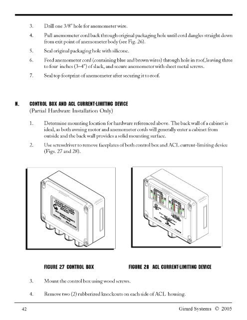
2. Use screwdriver to remove faceplates ofboth control box <strong>and</strong>ACL current-limiting device<br />
(Figs. 27 <strong>and</strong> 28).<br />
FIGURE 27 CONTROL BOX FIGURE 28 ACL CURRENT-LIMITING DEVICE<br />
3.<br />
4.<br />
Mount the control box using wood screws.<br />
Remove two (2) rubberized knockouts on each side ofACL housing.<br />
42<br />
<strong>Girard</strong> <strong>Systems</strong> © 2005