Girard Systems- Warranty and Freight Procedures
Girard Systems- Warranty and Freight Procedures
Girard Systems- Warranty and Freight Procedures

Create successful ePaper yourself
Turn your PDF publications into a flip-book with our unique Google optimized e-Paper software.
--------------- GIRARD<br />
SYSTEMs"<br />
8) Ifthe armyou are replacinghas a fIXed bolt insert the arm into the shoulder ensuring that the<br />
fixed bolt on the arm goes through the pitch adjustment assembly, throughthe square tube, <strong>and</strong><br />
though the washer,which are components inside the shoulder. Insert the front, loose bolt <strong>and</strong><br />
nut.<br />
Ifthe arm you are replacingdoes nothave a fIXed bolt use the bolt supplied with the arm to<br />
slide through the square tube for the shoulder support then through the pitch adjust assembly<br />
<strong>and</strong>into the arm connection plate. Insertthe front, loose bolt <strong>and</strong> nut.<br />
9) Proceedwith un-b<strong>and</strong>ing arm very carefully as this arm is under heavytension than fasten to<br />
lead rail refer to #8 procedure.<br />
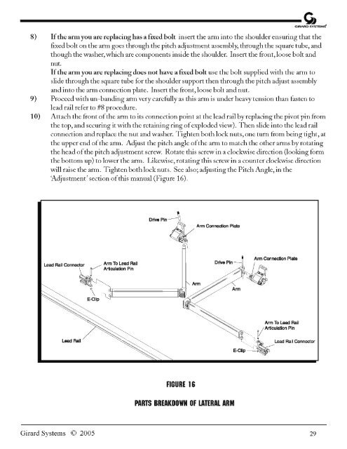
10) Attach the front ofthe arm to its connection point at the lead rail byreplacing the pivot pin from<br />
the top, <strong>and</strong> securing itwith the retaining ring ofexploded view). Then slide into the lead rail<br />
connection <strong>and</strong> replace the nut <strong>and</strong>washer. Tighten both lock nuts, one turn from being tight, at<br />
the upper end ofthe arm. Adjust the pitch angle ofthe arm to match the other arms by rotating<br />
the head ofthe pitch adjustment screw. Rotate this screw in a clockwise direction (looking form<br />
the bottom up) to lower the arm. Likewise, rotating this screw in a counter clockwise direction<br />
will raise the arm. Tighten bothlocknuts. See also; adjusting the Pitch Angle, in the<br />
'Adjustment' section ofthis manual (Figure 16).<br />
Drive Pin----4<br />
~ Arm Connection Plate<br />
o \<br />
Lead Rail Connector V Arm To Lead Rail<br />
~..J"••.:rtiCUlation Pin<br />
Drive Pin<br />
\ ~.====~~o Arm ~ Arm<br />
E-Clip .••.'1',L-----------'_ACy/<br />
'/<br />
Arm Connection Plate<br />
~<br />
Arm To Lead Rail<br />
"'",_,VArticulation Pin<br />
Lead Rail<br />
~. ~,_'~~ Lead Rail Connector<br />
E-CIiP-~<br />
FIGURE 16<br />
PARTS BREAKDOWN OF LATERAL ARM<br />
<strong>Girard</strong> <strong>Systems</strong> © 2005 29