Model 610AR Installation and Maintence Instructions Drive Axle Air ...
Model 610AR Installation and Maintence Instructions Drive Axle Air ...
Model 610AR Installation and Maintence Instructions Drive Axle Air ...

Create successful ePaper yourself
Turn your PDF publications into a flip-book with our unique Google optimized e-Paper software.
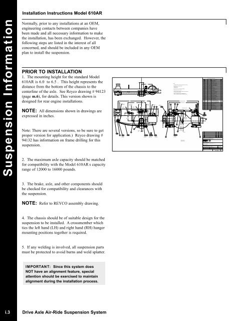
1 22267001235/8 BOLTSTYP 12X3/8 BOLTSTYP 2XTORQUE TO300 FT LBS3 1/46.2RIDE HEIGHT7281 1/4 TYP ON ALLFRAME HEIGHTS81/2 BOLTSTYP 4X916 1/44 PINIONANGLE3 5/82119701510 1/213 REF5/8 BOLTSTYP 4X6 1/25/8 BOLTSTYP 4X30 3125B25A10 11 532 11 512 13TORQUE TOTORQUE TOTORQUE TO300 FT LBS150-175 FT LBS25-30 FT LBS3 1/2REFTORQUE TO40-45 FT LBS29282120001NOTES:1. SUSPENSION RATINGS: GROUND LOAD (GAWR) 12,000-16,000 LBS.2. AXLE TRAVEL IS 2.3" UP AND 2.8" DOWNPINION ANGLE IS -4‘RIDE HEIGHT IS 6.2"3. AXLE SHOWN: 5.236 X 4.606 (19060S), REAR ENGINE4. SOME LINES LEFT OUT FOR CLARITY.5. FRAME ATTACHMENT FASTENERS SUPPLIED BY THE CUSTOMER ANDARE TO BE SAE GRADE 5 MINIMUM.6. WEIGHT OF SUSPENSION WITHOUT FASTENERS IS 276 LB.WEIGHT OF SUSPENSION COMPLETE IS APPROXIMATELY 289 LB.1815 16 171937 BEAM SPRING SPACING~ BOWL, HOUSING34 FRAME SPACINGASSEMBLE BOLT SIDE UP1 1/2 MIN GAPBETWEEN TRACKROD AND HIGHESTPOINT ON BOWLWELD AT ASSEMBLY~ CHASSISTORQUE TO14 400 FT LBS21BACK VIEW, NOT ATRUE PROJECTION.202633ITEM PART NO. DWG NO.DESCRIPTION1 2267001 96117 HANGER ASSEMBLY, LH2 2267002 96117 HANGER ASSEMBLY, RH3 2111301 94024 SPACER, WEAR4 2301701 91014 BOLT, M20x2.5 x 140 GR 10.95 1434401 93281 LOCK NUT, 3/4-16 UNF GR 86 2115301 94049#1 SPRING BEAM ASSEMBLY, LH7 2115302 94049#1 SPRING BEAM ASSEMBLY, RH8 2119901 94085 BRACKET9 2118106 94074#6 AXLE SEAT 4‘10 2083906 93397#6 U-BOLT, 3/4-16 UNF11 2085201 93403 FLAT WASHER, 3/4 (CLOSE FIT)12 1292001 93280 NUT, 1/2-13 UNC GR 513 T170562159 LOCK WASHER, 1/214 2119701 94083 BOTTOM PLATE ASSEMBLY, LH15 1735601 62158 BOLT, 7/8-9 UNC X 5 1/2 GR 516 1009201 93281 LOCK NUT, 7/8-9 UNC GR B17 T729271078 FLAT WASHER, 7/818 2108401 94011 AXLE BRACKET, TRACK ROD19 1642901 87109 TRACK ROD, ADJUSTABLE20 1827301 89479 FRAME BRACKET, TRACK ROD21 211970294083 BOTTOM PLATE ASSEMBLY, RH22 2120002 94086 MOUNTING BRACKET23 2016101 92289 SELF TAPPING SCREW, 1/4 X 2 1/224 2083801 93396 HEIGHT CONTROL VALVE25 N/A N/A SHOCK ABSORBER- KONI 90-189626 2118301 94076 UPPER SHOCK ABSORBER BRACKET27 1289001 82069 BOLT, 3/4-16 UNF X 7 GR 528 0821101 93280 NUT, 3/4-16 UNF2 REF29 T316462159 LOCK WASHER, 3/42 REF30 2116201 94058 UPPER AIR SPRING BRKT2 REF31 2077301 79167 AIR SPRING WITH UPPER BRACKET32 1524601 82069 BOLT, 3/4-16 UNF X 6 GR 833 2137001 94177 T.ROD FRAME DOUBLER34 2301801 94064 LOCKNUT- M20x2.5 CLASS 1027TORQUE TO150-175 FT LBSORIGREV.25B25ARELEASEDDESCRIPTIONTHIS DRAWING IS THE PROPERTY OF TUTHILL CORPORATION, AND IS NOT TO BE USEDIN ANY WAY DETRIMENTAL TO ITS INTERESTS. THIS DRAWING IS SUBJECT TO RETURNUPON REQUEST. ALL COPIES OF THIS ELECTRONIC DOCUMENT, WHETHER ELECTRONIC,PRINTED, OR OTHERWISE, ARE UNCONTROLLED DOCUMENTS.ALLOWABLE TOLERANCES UNLESS SPECIFIED: IN ADDITION, ALL PARTS MUST MEET REQUIREMENTSFRACTIONAL : +/- 1/16" [1.6mm] OF MS01000 REV A, "GENERAL DRAWING NOTES".2 DECIMAL PLACES: +/- 0.03" [0.8mm]3 DECIMAL PLACES: +/- 0.010" [0.25mm]ANGULAR : +/- 1 DEGREENOTES IN BRACKETS [] ARE METRIC UNITSTITLE:REAR SUSPENSION ASSEMBLY, -4‘ PINION,37" SPRING CENTERS, 34" FRAME- w/KONI SHK ABSDRAWN BY : G. SNYDERDRAWING DATE: 12/97CHECKED BY :APPROVED BY: RAMSUPERSEDES DRAWING OFPART NUMBER:11 525BILL OF MATERIAL <strong>610AR</strong> 94123#5BBDRAWING NUMBER:9287CHANGE NO.MODEL:SCALE: 1/412-10-97DATESPARTAN<strong>610AR</strong>SHEET:QTY<strong>Installation</strong> <strong>Instructions</strong> <strong>Model</strong> <strong>610AR</strong>Suspension InformationNormally, prior to any installations at an OEM,engineering contacts between companies havebeen made <strong>and</strong> all necessary information to makethe installation, has been exchanged. However, thefollowing steps are listed in the interest of allconcerned, <strong>and</strong> should be included in any OEMplan to install the suspension.PRIOR TO INSTALLATION1. The mounting height for the st<strong>and</strong>ard <strong>Model</strong><strong>610AR</strong> is 6.0 to 6.5 . This height represents thedistance from the bottom of the chassis to thecenterline of the axle. See Reyco drawing # 94123(page m.6), for details. This version shown isdesigned for rear engine installations.NOTE: All dimensions shown in drawings areexpressed in inches.Note: There are several versions, so be sure to getproper version for application.) Reyco drawing #94132 has information on frame drilling for thissuspension.2. The maximum axle capacity should be matchedfor compatibility with the <strong>Model</strong> <strong>610AR</strong> s capacityrange of 12000 to 16000 pounds.4 34 62422 2325A 1288802 79169 SLEEVE-SHOCK ABSORBER BUSHING25B 1289502 93403 WASHER-SHOCK ABSORBER BUSHINGINDUSTRIES INC.94123#5C5C3. The brake, axle, <strong>and</strong> other components shouldbe checked for compatibility <strong>and</strong> clearances withthe suspension.NOTE: Refer to REYCO assembly drawing.4. The chassis should be of suitable design for thesuspension to be installed. A crossmember whichties the left h<strong>and</strong> (LH) <strong>and</strong> right h<strong>and</strong> (RH) hangermounting positions together is required.5. If any welding is involved, all suspension partsmust be protected to avoid burns <strong>and</strong> weld splatter.IMPORTANT: Since this system doesNOT have an alignment feature, specialattention should be exercised to maintainalignment during the installation process.i.3 <strong>Drive</strong> <strong>Axle</strong> <strong>Air</strong>-Ride Suspension System