Girard Awnings R
Girard Awnings R
Girard Awnings R

Create successful ePaper yourself
Turn your PDF publications into a flip-book with our unique Google optimized e-Paper software.
2.2.4 Low Voltage Connections<br />
The low-voltage connections are described in detail in section 4. The low voltage control<br />
inputs should be connected to the appropriate mating halves for the connectors mounted to<br />
the ACMC board. As with the high-voltage connections, the provided strain relief should<br />
be utilised. The two rightmost strain-relief’s, one on either side of the box, are suggested<br />
for the low-voltage connections.<br />
2.2.5 RF Antenna<br />
On those ACMC boards with RF Communication capabilities, an RF antenna wire extends<br />
from the lower right corner of the board. This wire should pass through the drilled hole<br />
relief and out of the enclosure. It is important that this wire not be shortened (standard<br />
length is 9.5 inches), coiled or folded in any way. The antenna wire should be well<br />
separated from other wires, and kept clear of surrounding metallic objects.<br />
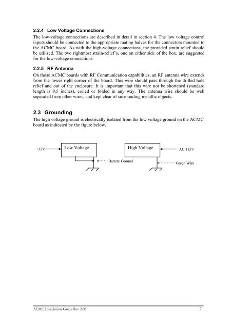
2.3 Grounding<br />
The high voltage ground is electrically isolated from the low voltage ground on the ACMC<br />
board as indicated by the figure below.<br />
+12V Low Voltage<br />
High Voltage<br />
AC 115V<br />
Battery Ground<br />
Green Wire<br />
ACMC Installation Guide Rev 2.08 7