Girard Awnings R
Girard Awnings R
Girard Awnings R

Create successful ePaper yourself
Turn your PDF publications into a flip-book with our unique Google optimized e-Paper software.
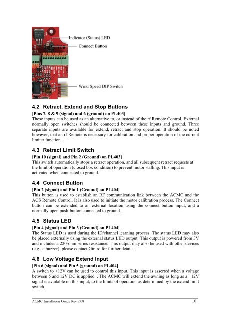
4.2 Retract, Extend and Stop Buttons<br />
[Pins 7, 8 & 9 (signal) and 6 (ground) on PL403]<br />
These inputs can be used as an alternative to, or instead of the rf Remote Control. External<br />
normally open switches should be connected between these inputs and ground. Three<br />
separate inputs are available for extend, retract and stop operation. It should be noted<br />
however, that an rf Remote is necessary for calibration and proper operation of the current<br />
limiter function.<br />
4.3 Retract Limit Switch<br />
[Pin 10 (signal) and Pin 2 (Ground) on PL403]<br />
This switch automatically stops a retract operation, and all subsequent retract requests at<br />
the limit of operation (closed box condition) to prevent motor stalling. This input is<br />
activated when connected to ground.<br />
4.4 Connect Button<br />
[Pin 2 (signal) and Pin 1 (Ground) on PL404]<br />
This button is used to establish an RF communication link between the ACMC and the<br />
ACS Remote Control. It is also used to initiate the motor calibration process. The Connect<br />
button can be extended to an external location using the connect button input, and a<br />
normally open push-button connected to ground.<br />
4.5 Status LED<br />
[Pin 4 (signal) and Pin 3 (Ground) on PL404]<br />
The Status LED is used during the ID/channel learning process. The status LED may also<br />
be placed externally using the external status LED output. This output is powered from 3V<br />
and includes a 220-ohm series resistance. This output may also be used with other devices<br />
(e.g., a buzzer); please contact <strong>Girard</strong> for further details.<br />
4.6 Low Voltage Extend Input<br />
[Pin 6 (signal) and Pin 5 (ground) on PL404]<br />
A switch to +12V can be used to control this input. This input is asserted when a voltage<br />
between 5 and 12V DC is applied. . The ACMC will extend the awning as long as a +12V<br />
signal is available on this input, to the limits of operation as determined by the extend limit<br />
switch.<br />
ACMC Installation Guide Rev 2.08 10