Dell Inspiron 1100, 5100, and 5150 Service Manual - Elhvb.com
Dell Inspiron 1100, 5100, and 5150 Service Manual - Elhvb.com
Dell Inspiron 1100, 5100, and 5150 Service Manual - Elhvb.com

Create successful ePaper yourself
Turn your PDF publications into a flip-book with our unique Google optimized e-Paper software.
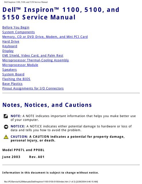
<strong>Dell</strong> <strong>Inspiron</strong> <strong>1100</strong>, <strong>5100</strong>, <strong>and</strong> <strong>5150</strong> <strong>Service</strong> <strong>Manual</strong><br />
<strong>Dell</strong> <strong>Inspiron</strong> <strong>1100</strong>, <strong>5100</strong>, <strong>and</strong><br />
<strong>5150</strong> <strong>Service</strong> <strong>Manual</strong><br />
Before You Begin<br />
System Components<br />
Memory, CD or DVD Drive, Modem, <strong>and</strong> Mini PCI Card<br />
Hard Drive<br />
Keyboard<br />
Display<br />
EMI Shield, Video Card, <strong>and</strong> Palm Rest<br />
Microprocessor Thermal-Cooling Assembly<br />
Microprocessor Module<br />
Speakers<br />
System Board<br />
Flashing the BIOS<br />
Base Plastics<br />
Pinout Assignments for I/O Connectors<br />
Notes, Notices, <strong>and</strong> Cautions<br />
NOTE: A NOTE indicates important information that helps you make better use<br />
of your <strong>com</strong>puter.<br />
NOTICE: A NOTICE indicates either potential damage to hardware or loss of<br />
data <strong>and</strong> tells you how to avoid the problem.<br />
CAUTION: A CAUTION indicates a potential for property damage,<br />
personal injury, or death.<br />
Model PP07L <strong>and</strong> PP08L<br />
June 2003 Rev. A01<br />
Information in this document is subject to change without notice.<br />
file:///F|/<strong>Service</strong>%20<strong>Manual</strong>s/<strong>Dell</strong>/<strong>Inspiron</strong>/<strong>1100</strong>-<strong>5100</strong>-<strong>5150</strong>/index.htm (1 of 2) [2/28/2004 6:46:15 AM]
Before You Begin: <strong>Dell</strong> <strong>Inspiron</strong> <strong>1100</strong>, <strong>5100</strong>, <strong>and</strong> <strong>5150</strong> <strong>Service</strong> <strong>Manual</strong><br />
Back to Contents Page<br />
Before You Begin<br />
<strong>Dell</strong> <strong>Inspiron</strong> <strong>1100</strong>, <strong>5100</strong>, <strong>and</strong> <strong>5150</strong> <strong>Service</strong> <strong>Manual</strong><br />
Preparing to Work Inside the Computer<br />
Re<strong>com</strong>mended Tools<br />
Computer Orientation<br />
Screw Identification<br />
Preparing to Work Inside the Computer<br />
CAUTION: Only a certified service technician should perform repairs on<br />
your <strong>com</strong>puter. Damage due to servicing that is not authorized by <strong>Dell</strong><br />
is not covered by your warranty. Read <strong>and</strong> follow the safety instructions<br />
in the Owner's <strong>Manual</strong> that came with the <strong>com</strong>puter.<br />
CAUTION: To prevent static damage to <strong>com</strong>ponents inside your<br />
<strong>com</strong>puter, discharge static electricity from your body before you touch<br />
any of your <strong>com</strong>puter's electronic <strong>com</strong>ponents. You can do so by<br />
touching an unpainted metal surface.<br />
CAUTION: H<strong>and</strong>le <strong>com</strong>ponents <strong>and</strong> cards with care. Do not touch the<br />
<strong>com</strong>ponents or contacts on a card. Hold a card by its edges or by its<br />
metal mounting bracket. Hold a <strong>com</strong>ponent such as a microprocessor by<br />
its edges, not by its pins.<br />
NOTICE: To avoid damaging the <strong>com</strong>puter, perform the following steps before<br />
you begin working inside the <strong>com</strong>puter.<br />
1. Ensure that the work surface is flat <strong>and</strong> clean to prevent scratching the<br />
<strong>com</strong>puter cover.<br />
2. Save any work in progress <strong>and</strong> exit all open programs.<br />
3. Turn off the <strong>com</strong>puter <strong>and</strong> all attached devices.<br />
file:///F|/<strong>Service</strong>%20<strong>Manual</strong>s/<strong>Dell</strong>/<strong>Inspiron</strong>/<strong>1100</strong>-<strong>5100</strong>-<strong>5150</strong>/beginb.htm (1 of 7) [2/28/2004 6:46:35 AM]
Before You Begin: <strong>Dell</strong> <strong>Inspiron</strong> <strong>1100</strong>, <strong>5100</strong>, <strong>and</strong> <strong>5150</strong> <strong>Service</strong> <strong>Manual</strong><br />
NOTE: Ensure that the <strong>com</strong>puter is off <strong>and</strong> not in a power management mode.<br />
If you cannot shut down the <strong>com</strong>puter using the <strong>com</strong>puter operating system,<br />
press <strong>and</strong> hold the power button for 4 seconds.<br />
4. Disconnect the <strong>com</strong>puter from the electrical outlet.<br />
5. Close the display <strong>and</strong> turn the <strong>com</strong>puter upside down on a flat work surface.<br />
NOTICE: To avoid damaging the system board, you must remove the main<br />
battery before you service the <strong>com</strong>puter.<br />
6. Slide <strong>and</strong> hold the battery-bay latch release on the bottom of the <strong>com</strong>puter, <strong>and</strong><br />
then remove the battery from the bay.<br />
1 battery<br />
2 battery-bay latch<br />
release<br />
file:///F|/<strong>Service</strong>%20<strong>Manual</strong>s/<strong>Dell</strong>/<strong>Inspiron</strong>/<strong>1100</strong>-<strong>5100</strong>-<strong>5150</strong>/beginb.htm (2 of 7) [2/28/2004 6:46:35 AM]
Before You Begin: <strong>Dell</strong> <strong>Inspiron</strong> <strong>1100</strong>, <strong>5100</strong>, <strong>and</strong> <strong>5150</strong> <strong>Service</strong> <strong>Manual</strong><br />
7. To avoid possible damage to the system board, wait 10 to 20 seconds <strong>and</strong> then<br />
disconnect any attached devices.<br />
8. Disconnect all other external cables from the <strong>com</strong>puter.<br />
9. Remove any installed PC Cards from the PC Card slot.<br />
Re<strong>com</strong>mended Tools<br />
The procedures in this manual require the following tools:<br />
● #1 Phillips screwdriver<br />
● ¼-inch flat-blade screwdriver<br />
● Small plastic scribe<br />
● Hex nut driver<br />
● Flash BIOS update program CD<br />
Computer Orientation<br />
file:///F|/<strong>Service</strong>%20<strong>Manual</strong>s/<strong>Dell</strong>/<strong>Inspiron</strong>/<strong>1100</strong>-<strong>5100</strong>-<strong>5150</strong>/beginb.htm (3 of 7) [2/28/2004 6:46:35 AM]
Before You Begin: <strong>Dell</strong> <strong>Inspiron</strong> <strong>1100</strong>, <strong>5100</strong>, <strong>and</strong> <strong>5150</strong> <strong>Service</strong> <strong>Manual</strong><br />
1 back<br />
2 right<br />
3 front<br />
4 left<br />
Screw Identification<br />
When you are removing <strong>and</strong> replacing <strong>com</strong>ponents, photocopy "Screw Identification"<br />
as a tool to lay out <strong>and</strong> keep track of the screws. The placemat provides the number<br />
of screws <strong>and</strong> their sizes.<br />
file:///F|/<strong>Service</strong>%20<strong>Manual</strong>s/<strong>Dell</strong>/<strong>Inspiron</strong>/<strong>1100</strong>-<strong>5100</strong>-<strong>5150</strong>/beginb.htm (4 of 7) [2/28/2004 6:46:35 AM]
Before You Begin: <strong>Dell</strong> <strong>Inspiron</strong> <strong>1100</strong>, <strong>5100</strong>, <strong>and</strong> <strong>5150</strong> <strong>Service</strong> <strong>Manual</strong><br />
Hard Drive Door:<br />
(2 each)<br />
Keyboard<br />
to Computer Base:<br />
(4 each)<br />
Display Bezel:<br />
(5 each)<br />
Screw Covers (2 each)<br />
Display Bumpers (3 each)<br />
Modem to<br />
System Board:<br />
(2 each)<br />
Display Assembly<br />
to Back Panel:<br />
(2 each)<br />
Display Panel:<br />
(8 each)<br />
file:///F|/<strong>Service</strong>%20<strong>Manual</strong>s/<strong>Dell</strong>/<strong>Inspiron</strong>/<strong>1100</strong>-<strong>5100</strong>-<strong>5150</strong>/beginb.htm (5 of 7) [2/28/2004 6:46:35 AM]<br />
Optical Drive:<br />
(1 each)<br />
Hinge Bracket<br />
to Computer Base:<br />
(4 each)<br />
Display Latch:<br />
(2 each)
Before You Begin: <strong>Dell</strong> <strong>Inspiron</strong> <strong>1100</strong>, <strong>5100</strong>, <strong>and</strong> <strong>5150</strong> <strong>Service</strong> <strong>Manual</strong><br />
EMI Shield:<br />
(1 each)<br />
Video Card<br />
to System Board:<br />
(2 each)<br />
Battery Bay Shield<br />
to System Board:<br />
(2 each)<br />
Top of Palm Rest to<br />
Computer Base:<br />
(2 each)<br />
Palm Rest to<br />
Battery Bay:<br />
(1 each)<br />
Left Antenna<br />
to Hard Drive <strong>and</strong><br />
Optical Drive Cages<br />
(<strong>Inspiron</strong> <strong>5100</strong> <strong>and</strong> <strong>5150</strong><br />
only):<br />
(2 each)<br />
file:///F|/<strong>Service</strong>%20<strong>Manual</strong>s/<strong>Dell</strong>/<strong>Inspiron</strong>/<strong>1100</strong>-<strong>5100</strong>-<strong>5150</strong>/beginb.htm (6 of 7) [2/28/2004 6:46:35 AM]<br />
Palm Rest to<br />
Base Plastics:<br />
(12 each)<br />
System Board to<br />
Base Plastics:<br />
(3 each, hard drive cage)<br />
(2 each, optical drive<br />
cage)
Before You Begin: <strong>Dell</strong> <strong>Inspiron</strong> <strong>1100</strong>, <strong>5100</strong>, <strong>and</strong> <strong>5150</strong> <strong>Service</strong> <strong>Manual</strong><br />
Back to Contents Page<br />
file:///F|/<strong>Service</strong>%20<strong>Manual</strong>s/<strong>Dell</strong>/<strong>Inspiron</strong>/<strong>1100</strong>-<strong>5100</strong>-<strong>5150</strong>/beginb.htm (7 of 7) [2/28/2004 6:46:35 AM]
System Components: <strong>Dell</strong> <strong>Inspiron</strong> <strong>1100</strong>, <strong>5100</strong>, <strong>and</strong> <strong>5150</strong> <strong>Service</strong> <strong>Manual</strong><br />
Back to Contents Page<br />
System Components<br />
<strong>Dell</strong> <strong>Inspiron</strong> <strong>1100</strong>, <strong>5100</strong>, <strong>and</strong> <strong>5150</strong> <strong>Service</strong> <strong>Manual</strong><br />
CAUTION: Only a certified service technician should perform repairs on<br />
your <strong>com</strong>puter. Damage due to servicing that is not authorized by <strong>Dell</strong><br />
is not covered by your warranty.<br />
NOTICE: Unless otherwise noted, each procedure in this document assumes<br />
that a part can be replaced by performing the removal procedure in reverse<br />
order.<br />
file:///F|/<strong>Service</strong>%20<strong>Manual</strong>s/<strong>Dell</strong>/<strong>Inspiron</strong>/<strong>1100</strong>-<strong>5100</strong>-<strong>5150</strong>/systemb.htm (1 of 3) [2/28/2004 6:46:36 AM]
System Components: <strong>Dell</strong> <strong>Inspiron</strong> <strong>1100</strong>, <strong>5100</strong>, <strong>and</strong> <strong>5150</strong> <strong>Service</strong> <strong>Manual</strong><br />
1 display 11 base plastics<br />
2 display-feed flex cable 12 battery<br />
3 hinge cover 13 CD or DVD drive<br />
4 keyboard 14 left antenna<br />
(<strong>Inspiron</strong> <strong>5100</strong><br />
<strong>and</strong> <strong>5150</strong> only)<br />
5 palm rest 15 hard drive<br />
6 microprocessor thermalcooling<br />
assembly<br />
16 system board<br />
7 EMI shield 17 modem<br />
8 battery bay shield 18 Mini PCI card<br />
(<strong>Inspiron</strong> <strong>5100</strong> <strong>and</strong><br />
<strong>5150</strong> only)<br />
9 microprocessor 19 video card (<strong>Inspiron</strong><br />
<strong>5100</strong> <strong>and</strong> <strong>5150</strong><br />
only)<br />
10 speakers<br />
Back to Contents Page<br />
file:///F|/<strong>Service</strong>%20<strong>Manual</strong>s/<strong>Dell</strong>/<strong>Inspiron</strong>/<strong>1100</strong>-<strong>5100</strong>-<strong>5150</strong>/systemb.htm (2 of 3) [2/28/2004 6:46:36 AM]
System Components: <strong>Dell</strong> <strong>Inspiron</strong> <strong>1100</strong>, <strong>5100</strong>, <strong>and</strong> <strong>5150</strong> <strong>Service</strong> <strong>Manual</strong><br />
file:///F|/<strong>Service</strong>%20<strong>Manual</strong>s/<strong>Dell</strong>/<strong>Inspiron</strong>/<strong>1100</strong>-<strong>5100</strong>-<strong>5150</strong>/systemb.htm (3 of 3) [2/28/2004 6:46:36 AM]
Memory, CD or DVD Drive, Modem, <strong>and</strong> Mini PCI Card: <strong>Dell</strong> <strong>Inspiron</strong> <strong>1100</strong>, <strong>5100</strong>, <strong>and</strong> <strong>5150</strong> <strong>Service</strong> <strong>Manual</strong><br />
Back to Contents Page<br />
Memory, CD or DVD Drive, Modem, <strong>and</strong><br />
Mini PCI Card<br />
<strong>Dell</strong> <strong>Inspiron</strong> <strong>1100</strong>, <strong>5100</strong>, <strong>and</strong> <strong>5150</strong> <strong>Service</strong> <strong>Manual</strong><br />
Memory<br />
CD or DVD Drive<br />
Modem<br />
Mini PCI Card (<strong>Inspiron</strong> <strong>5100</strong> <strong>and</strong> <strong>5150</strong> Only)<br />
Memory<br />
Removing the Memory Modules<br />
CAUTION: Before working inside your <strong>Dell</strong> <strong>com</strong>puter, read the safety<br />
instructions in your Owner's <strong>Manual</strong>.<br />
CAUTION: To prevent static damage to <strong>com</strong>ponents inside your<br />
<strong>com</strong>puter, discharge static electricity from your body before you touch<br />
any of your <strong>com</strong>puter's electronic <strong>com</strong>ponents. You can do so by<br />
touching an unpainted metal surface.<br />
NOTE: Memory modules purchased from <strong>Dell</strong> are covered under your <strong>com</strong>puter<br />
warranty.<br />
1. Follow the instructions in "Preparing to Work Inside the Computer."<br />
2. Turn the <strong>com</strong>puter over, loosen the captive screw (labeled "circle M") in the<br />
memory module cover, <strong>and</strong> lift the cover away from the <strong>com</strong>puter.<br />
file:///F|/<strong>Service</strong>%20<strong>Manual</strong>s/<strong>Dell</strong>/<strong>Inspiron</strong>/<strong>1100</strong>-<strong>5100</strong>-<strong>5150</strong>/upgrades.htm (1 of 13) [2/28/2004 6:46:37 AM]
Memory, CD or DVD Drive, Modem, <strong>and</strong> Mini PCI Card: <strong>Dell</strong> <strong>Inspiron</strong> <strong>1100</strong>, <strong>5100</strong>, <strong>and</strong> <strong>5150</strong> <strong>Service</strong> <strong>Manual</strong><br />
1 captive screw<br />
2 memory module cover<br />
3. Use your fingertips to carefully spread apart the securing clips on each end of<br />
the memory module connector until the module pops up.<br />
4. Remove the module from the connector.<br />
file:///F|/<strong>Service</strong>%20<strong>Manual</strong>s/<strong>Dell</strong>/<strong>Inspiron</strong>/<strong>1100</strong>-<strong>5100</strong>-<strong>5150</strong>/upgrades.htm (2 of 13) [2/28/2004 6:46:37 AM]
Memory, CD or DVD Drive, Modem, <strong>and</strong> Mini PCI Card: <strong>Dell</strong> <strong>Inspiron</strong> <strong>1100</strong>, <strong>5100</strong>, <strong>and</strong> <strong>5150</strong> <strong>Service</strong> <strong>Manual</strong><br />
1 memory module<br />
2 securing clips<br />
Installing the Memory Modules<br />
NOTE: If the memory module is not installed properly, the <strong>com</strong>puter may not<br />
boot properly. No error message indicates this failure.<br />
1. Align the notch in the module edge connector with the tab in the connector slot.<br />
2. Slide the module firmly into the slot at a 45-degree angle, <strong>and</strong> rotate the<br />
module down until it clicks into place. If you do not feel the click, remove the<br />
module <strong>and</strong> reinstall it.<br />
3. Replace the cover <strong>and</strong> tighten the captive screw.<br />
NOTICE: If the memory module cover is difficult to close, remove the module<br />
<strong>and</strong> reinstall it. Forcing the cover to close may damage your <strong>com</strong>puter.<br />
4. Insert the battery into the battery bay, or connect the AC adapter to your<br />
<strong>com</strong>puter <strong>and</strong> an electrical outlet.<br />
file:///F|/<strong>Service</strong>%20<strong>Manual</strong>s/<strong>Dell</strong>/<strong>Inspiron</strong>/<strong>1100</strong>-<strong>5100</strong>-<strong>5150</strong>/upgrades.htm (3 of 13) [2/28/2004 6:46:37 AM]
Memory, CD or DVD Drive, Modem, <strong>and</strong> Mini PCI Card: <strong>Dell</strong> <strong>Inspiron</strong> <strong>1100</strong>, <strong>5100</strong>, <strong>and</strong> <strong>5150</strong> <strong>Service</strong> <strong>Manual</strong><br />
5. Turn on the <strong>com</strong>puter.<br />
As the <strong>com</strong>puter boots, it detects the additional memory <strong>and</strong> automatically updates<br />
the system configuration information.<br />
To confirm the amount of memory installed in the <strong>com</strong>puter, click the Start button,<br />
click Help <strong>and</strong> Support, <strong>and</strong> then click Computer Information.<br />
CD or DVD Drive<br />
Removing the CD or DVD Drive<br />
CAUTION: Before working inside your <strong>Dell</strong> <strong>com</strong>puter, read the safety<br />
instructions in your Owner's <strong>Manual</strong>.<br />
CAUTION: To prevent static damage to <strong>com</strong>ponents inside your<br />
<strong>com</strong>puter, discharge static electricity from your body before you touch<br />
any of your <strong>com</strong>puter's electronic <strong>com</strong>ponents. You can do so by<br />
touching an unpainted metal surface.<br />
1. Follow the instructions in "Preparing to Work Inside the Computer."<br />
2. Turn the <strong>com</strong>puter over, <strong>and</strong> remove the M2.5 x 8-mm screw labeled "O" next<br />
to the memory module cover.<br />
3. Loosen the captive screw (labeled "circle M") in the memory module cover, <strong>and</strong><br />
lift the cover away from the <strong>com</strong>puter.<br />
file:///F|/<strong>Service</strong>%20<strong>Manual</strong>s/<strong>Dell</strong>/<strong>Inspiron</strong>/<strong>1100</strong>-<strong>5100</strong>-<strong>5150</strong>/upgrades.htm (4 of 13) [2/28/2004 6:46:37 AM]
Memory, CD or DVD Drive, Modem, <strong>and</strong> Mini PCI Card: <strong>Dell</strong> <strong>Inspiron</strong> <strong>1100</strong>, <strong>5100</strong>, <strong>and</strong> <strong>5150</strong> <strong>Service</strong> <strong>Manual</strong><br />
1 captive screw<br />
2 memory module cover<br />
4. Press the lever next to the memory module connectors in the direction of the<br />
arrow on the lever (towards the drive) to release the drive.<br />
file:///F|/<strong>Service</strong>%20<strong>Manual</strong>s/<strong>Dell</strong>/<strong>Inspiron</strong>/<strong>1100</strong>-<strong>5100</strong>-<strong>5150</strong>/upgrades.htm (5 of 13) [2/28/2004 6:46:37 AM]
Memory, CD or DVD Drive, Modem, <strong>and</strong> Mini PCI Card: <strong>Dell</strong> <strong>Inspiron</strong> <strong>1100</strong>, <strong>5100</strong>, <strong>and</strong> <strong>5150</strong> <strong>Service</strong> <strong>Manual</strong><br />
1 lever<br />
2 CD or DVD drive<br />
3 M2.5 x 8-mm screw<br />
labeled "O"<br />
5. Pull the drive out of the bay.<br />
Installing the CD or DVD Drive<br />
1. Slide the new drive into the bay until the drive is fully seated.<br />
2. Replace the memory module cover <strong>and</strong> tighten the captive screw.<br />
3. Replace the M2.5 x 8-mm screw next to the memory module cover.<br />
file:///F|/<strong>Service</strong>%20<strong>Manual</strong>s/<strong>Dell</strong>/<strong>Inspiron</strong>/<strong>1100</strong>-<strong>5100</strong>-<strong>5150</strong>/upgrades.htm (6 of 13) [2/28/2004 6:46:37 AM]
Memory, CD or DVD Drive, Modem, <strong>and</strong> Mini PCI Card: <strong>Dell</strong> <strong>Inspiron</strong> <strong>1100</strong>, <strong>5100</strong>, <strong>and</strong> <strong>5150</strong> <strong>Service</strong> <strong>Manual</strong><br />
Modem<br />
Removing the Modem<br />
CAUTION: Before working inside your <strong>Dell</strong> <strong>com</strong>puter, read the safety<br />
instructions in your Owner's <strong>Manual</strong>.<br />
CAUTION: To prevent static damage to <strong>com</strong>ponents inside your<br />
<strong>com</strong>puter, discharge static electricity from your body before you touch<br />
any of your <strong>com</strong>puter's electronic <strong>com</strong>ponents. You can do so by<br />
touching an unpainted metal surface.<br />
1. Follow the instructions in "Preparing to Work Inside the Computer."<br />
2. Turn the <strong>com</strong>puter over, loosen the captive screw (labeled "circle C") in the<br />
modem/Mini PCI card cover, <strong>and</strong> lift the cover away from the <strong>com</strong>puter.<br />
1 captive screw<br />
file:///F|/<strong>Service</strong>%20<strong>Manual</strong>s/<strong>Dell</strong>/<strong>Inspiron</strong>/<strong>1100</strong>-<strong>5100</strong>-<strong>5150</strong>/upgrades.htm (7 of 13) [2/28/2004 6:46:37 AM]
Memory, CD or DVD Drive, Modem, <strong>and</strong> Mini PCI Card: <strong>Dell</strong> <strong>Inspiron</strong> <strong>1100</strong>, <strong>5100</strong>, <strong>and</strong> <strong>5150</strong> <strong>Service</strong> <strong>Manual</strong><br />
2 modem/Mini PCI card<br />
cover<br />
3. Remove the two M2 x 3-mm screws securing the modem to the system board,<br />
<strong>and</strong> set them aside.<br />
4. Pull straight up on the attached pull-tab to lift the modem out of its connector<br />
on the system board <strong>and</strong> disconnect the modem cable.<br />
1 modem cable connector<br />
2 pull-tab<br />
3 modem cable<br />
4 M2 x 3-mm screws (2)<br />
Installing the Modem<br />
1. Connect the modem cable to the modem.<br />
file:///F|/<strong>Service</strong>%20<strong>Manual</strong>s/<strong>Dell</strong>/<strong>Inspiron</strong>/<strong>1100</strong>-<strong>5100</strong>-<strong>5150</strong>/upgrades.htm (8 of 13) [2/28/2004 6:46:37 AM]
Memory, CD or DVD Drive, Modem, <strong>and</strong> Mini PCI Card: <strong>Dell</strong> <strong>Inspiron</strong> <strong>1100</strong>, <strong>5100</strong>, <strong>and</strong> <strong>5150</strong> <strong>Service</strong> <strong>Manual</strong><br />
NOTICE: The cable connectors are keyed for correct insertion; do not force the<br />
connections.<br />
2. Align the modem with the screw holes, <strong>and</strong> press the modem into the connector<br />
on the system board.<br />
3. Install the two M2 x 3-mm screws to secure the modem to the system board.<br />
4. Replace the cover <strong>and</strong> tighten the captive screw.<br />
Mini PCI Card (<strong>Inspiron</strong> <strong>5100</strong> <strong>and</strong> <strong>5150</strong><br />
Only)<br />
Removing the Mini PCI Card<br />
CAUTION: Before working inside your <strong>Dell</strong> <strong>com</strong>puter, read the safety<br />
instructions in your Owner's <strong>Manual</strong>.<br />
CAUTION: To prevent static damage to <strong>com</strong>ponents inside your<br />
<strong>com</strong>puter, discharge static electricity from your body before you touch<br />
any of your <strong>com</strong>puter's electronic <strong>com</strong>ponents. You can do so by<br />
touching an unpainted metal surface.<br />
1. Follow the instructions in "Preparing to Work Inside the Computer."<br />
2. Turn the <strong>com</strong>puter over, loosen the captive screw (labeled "circle C") in the<br />
modem/Mini PCI card cover, <strong>and</strong> lift the cover away from the <strong>com</strong>puter.<br />
file:///F|/<strong>Service</strong>%20<strong>Manual</strong>s/<strong>Dell</strong>/<strong>Inspiron</strong>/<strong>1100</strong>-<strong>5100</strong>-<strong>5150</strong>/upgrades.htm (9 of 13) [2/28/2004 6:46:37 AM]
Memory, CD or DVD Drive, Modem, <strong>and</strong> Mini PCI Card: <strong>Dell</strong> <strong>Inspiron</strong> <strong>1100</strong>, <strong>5100</strong>, <strong>and</strong> <strong>5150</strong> <strong>Service</strong> <strong>Manual</strong><br />
1 captive screw<br />
2 modem/Mini PCI card<br />
cover<br />
3. Disconnect the Mini PCI card from the attached cables.<br />
file:///F|/<strong>Service</strong>%20<strong>Manual</strong>s/<strong>Dell</strong>/<strong>Inspiron</strong>/<strong>1100</strong>-<strong>5100</strong>-<strong>5150</strong>/upgrades.htm (10 of 13) [2/28/2004 6:46:37 AM]
Memory, CD or DVD Drive, Modem, <strong>and</strong> Mini PCI Card: <strong>Dell</strong> <strong>Inspiron</strong> <strong>1100</strong>, <strong>5100</strong>, <strong>and</strong> <strong>5150</strong> <strong>Service</strong> <strong>Manual</strong><br />
1 antenna cables<br />
2 metal securing tabs (2)<br />
3 Mini PCI card connector<br />
4 Mini PCI card<br />
4. Use your fingertips to carefully spread apart the securing taps on each end of<br />
the Mini PCI card connector until the card pops up.<br />
5. Lift the Mini PCI card out of its connector.<br />
Installing the Mini PCI Card<br />
NOTICE: To avoid damaging the Mini PCI card, never place cables on top of or<br />
under the card.<br />
NOTICE: The connectors are keyed to ensure correct insertion. If you feel<br />
resistance, check the connectors <strong>and</strong> realign the card.<br />
file:///F|/<strong>Service</strong>%20<strong>Manual</strong>s/<strong>Dell</strong>/<strong>Inspiron</strong>/<strong>1100</strong>-<strong>5100</strong>-<strong>5150</strong>/upgrades.htm (11 of 13) [2/28/2004 6:46:37 AM]
Memory, CD or DVD Drive, Modem, <strong>and</strong> Mini PCI Card: <strong>Dell</strong> <strong>Inspiron</strong> <strong>1100</strong>, <strong>5100</strong>, <strong>and</strong> <strong>5150</strong> <strong>Service</strong> <strong>Manual</strong><br />
1. Align the Mini PCI card with the connector at a 45-degree angle, <strong>and</strong> press the<br />
Mini PCI card into the connector until it clicks.<br />
1 antenna cables<br />
2 Mini PCI card connector<br />
3 Mini PCI card<br />
2. Connect the antenna cables to the Mini PCI card.<br />
NOTE: To prevent damage to the antenna cables, carefully fold the cables<br />
under the Mini PCI card before replacing the cover.<br />
3. Replace the cover <strong>and</strong> tighten the captive screw.<br />
Back to Contents Page<br />
file:///F|/<strong>Service</strong>%20<strong>Manual</strong>s/<strong>Dell</strong>/<strong>Inspiron</strong>/<strong>1100</strong>-<strong>5100</strong>-<strong>5150</strong>/upgrades.htm (12 of 13) [2/28/2004 6:46:37 AM]
Memory, CD or DVD Drive, Modem, <strong>and</strong> Mini PCI Card: <strong>Dell</strong> <strong>Inspiron</strong> <strong>1100</strong>, <strong>5100</strong>, <strong>and</strong> <strong>5150</strong> <strong>Service</strong> <strong>Manual</strong><br />
file:///F|/<strong>Service</strong>%20<strong>Manual</strong>s/<strong>Dell</strong>/<strong>Inspiron</strong>/<strong>1100</strong>-<strong>5100</strong>-<strong>5150</strong>/upgrades.htm (13 of 13) [2/28/2004 6:46:37 AM]
Hard Drive: <strong>Dell</strong> <strong>Inspiron</strong> <strong>1100</strong>, <strong>5100</strong>, <strong>and</strong> <strong>5150</strong> <strong>Service</strong> <strong>Manual</strong><br />
Back to Contents Page<br />
Hard Drive<br />
<strong>Dell</strong> <strong>Inspiron</strong> <strong>1100</strong>, <strong>5100</strong>, <strong>and</strong> <strong>5150</strong> <strong>Service</strong> <strong>Manual</strong><br />
Removing the Hard Drive<br />
CAUTION: If you remove the hard drive from the <strong>com</strong>puter when the<br />
drive is hot, do not touch the metal housing of the hard drive.<br />
CAUTION: Before working inside your <strong>com</strong>puter, read the safety<br />
instructions in your Owner's <strong>Manual</strong>.<br />
NOTICE: To prevent data loss, shut down your <strong>com</strong>puter before removing the<br />
hard drive. Do not remove the hard drive while the <strong>com</strong>puter is on, in st<strong>and</strong>by<br />
mode, or in hibernate mode.<br />
NOTICE: Hard drives are extremely fragile; even a slight bump can damage the<br />
drive.<br />
NOTE: <strong>Dell</strong> does not guarantee <strong>com</strong>patibility or provide support for hard drives<br />
from sources other than <strong>Dell</strong>.<br />
1. Follow the instructions in "Preparing to Work Inside the Computer."<br />
2. Turn the <strong>com</strong>puter over, <strong>and</strong> remove the two M2.5 x 5-mm hard drive screws.<br />
file:///F|/<strong>Service</strong>%20<strong>Manual</strong>s/<strong>Dell</strong>/<strong>Inspiron</strong>/<strong>1100</strong>-<strong>5100</strong>-<strong>5150</strong>/hdd.htm (1 of 3) [2/28/2004 6:46:38 AM]
Hard Drive: <strong>Dell</strong> <strong>Inspiron</strong> <strong>1100</strong>, <strong>5100</strong>, <strong>and</strong> <strong>5150</strong> <strong>Service</strong> <strong>Manual</strong><br />
1 M2.5 x 5-mm screws (2)<br />
2 hard drive<br />
NOTICE: When the hard drive is not in the <strong>com</strong>puter, store it in protective<br />
antistatic packaging. See "Protecting Against Electrostatic Discharge" in your<br />
Owner's <strong>Manual</strong>.<br />
3. Slide the hard drive out of the <strong>com</strong>puter.<br />
Installing the Hard Drive<br />
1. Remove the new drive from its packaging.<br />
Save the original packaging for storing or shipping the hard drive.<br />
file:///F|/<strong>Service</strong>%20<strong>Manual</strong>s/<strong>Dell</strong>/<strong>Inspiron</strong>/<strong>1100</strong>-<strong>5100</strong>-<strong>5150</strong>/hdd.htm (2 of 3) [2/28/2004 6:46:38 AM]
Hard Drive: <strong>Dell</strong> <strong>Inspiron</strong> <strong>1100</strong>, <strong>5100</strong>, <strong>and</strong> <strong>5150</strong> <strong>Service</strong> <strong>Manual</strong><br />
NOTICE: Use firm <strong>and</strong> even pressure to slide the drive into place. If you use<br />
excessive force, you may damage the connector.<br />
2. Insert the drive into the bay, <strong>and</strong> push the hard drive until it is fully seated in<br />
the bay.<br />
3. Replace <strong>and</strong> tighten the two M2.5 x 5-mm screws.<br />
4. Use the Operating System CD to install the operating system for your <strong>com</strong>puter.<br />
5. Use the Drivers <strong>and</strong> Utilities CD to install the drivers <strong>and</strong> utilities for your<br />
<strong>com</strong>puter.<br />
Back to Contents Page<br />
file:///F|/<strong>Service</strong>%20<strong>Manual</strong>s/<strong>Dell</strong>/<strong>Inspiron</strong>/<strong>1100</strong>-<strong>5100</strong>-<strong>5150</strong>/hdd.htm (3 of 3) [2/28/2004 6:46:38 AM]
Keyboard: <strong>Dell</strong> <strong>Inspiron</strong> <strong>1100</strong>, <strong>5100</strong>, <strong>and</strong> <strong>5150</strong> <strong>Service</strong> <strong>Manual</strong><br />
Back to Contents Page<br />
Keyboard<br />
<strong>Dell</strong> <strong>Inspiron</strong> <strong>1100</strong>, <strong>5100</strong>, <strong>and</strong> <strong>5150</strong> <strong>Service</strong> <strong>Manual</strong><br />
Removing the Keyboard<br />
CAUTION: Before working inside your <strong>Dell</strong> <strong>com</strong>puter, read the safety<br />
instructions in your Owner's <strong>Manual</strong>.<br />
CAUTION: To prevent static damage to <strong>com</strong>ponents inside your<br />
<strong>com</strong>puter, discharge static electricity from your body before you touch<br />
any of your <strong>com</strong>puter's electronic <strong>com</strong>ponents. You can do so by<br />
touching an unpainted metal surface.<br />
1. Follow the instructions in "Preparing to Work Inside the Computer."<br />
2. Use a small flat-blade screwdriver or plastic scribe to lift the notched right edge<br />
of the hinge cover, <strong>and</strong> pry the cover loose from the hinges <strong>and</strong> <strong>com</strong>puter base.<br />
file:///F|/<strong>Service</strong>%20<strong>Manual</strong>s/<strong>Dell</strong>/<strong>Inspiron</strong>/<strong>1100</strong>-<strong>5100</strong>-<strong>5150</strong>/keyboard.htm (1 of 6) [2/28/2004 6:46:39 AM]
Keyboard: <strong>Dell</strong> <strong>Inspiron</strong> <strong>1100</strong>, <strong>5100</strong>, <strong>and</strong> <strong>5150</strong> <strong>Service</strong> <strong>Manual</strong><br />
1 notched edge<br />
2 hinge cover<br />
3. Lift the hinge cover up <strong>and</strong> away from the hinges <strong>and</strong> <strong>com</strong>puter base.<br />
4. Remove the four M2 x 3-mm keyboard screws.<br />
file:///F|/<strong>Service</strong>%20<strong>Manual</strong>s/<strong>Dell</strong>/<strong>Inspiron</strong>/<strong>1100</strong>-<strong>5100</strong>-<strong>5150</strong>/keyboard.htm (2 of 6) [2/28/2004 6:46:39 AM]
Keyboard: <strong>Dell</strong> <strong>Inspiron</strong> <strong>1100</strong>, <strong>5100</strong>, <strong>and</strong> <strong>5150</strong> <strong>Service</strong> <strong>Manual</strong><br />
1 M2 x 3-mm screws (4)<br />
2 keyboard<br />
NOTICE: The keycaps on the keyboard are fragile, easily dislodged, <strong>and</strong> timeconsuming<br />
to replace. Be careful when removing <strong>and</strong> h<strong>and</strong>ling the keyboard.<br />
5. Lift the top of the keyboard out of the <strong>com</strong>puter base, <strong>and</strong> pull the keyboard out<br />
at an angle (towards the display). Rest the keyboard face down on the palm<br />
rest.<br />
6. Grasp the keyboard flex cable near the connector, <strong>and</strong> pull up on the flex cable<br />
to disconnect it from the interface connector on the system board.<br />
file:///F|/<strong>Service</strong>%20<strong>Manual</strong>s/<strong>Dell</strong>/<strong>Inspiron</strong>/<strong>1100</strong>-<strong>5100</strong>-<strong>5150</strong>/keyboard.htm (3 of 6) [2/28/2004 6:46:39 AM]
Keyboard: <strong>Dell</strong> <strong>Inspiron</strong> <strong>1100</strong>, <strong>5100</strong>, <strong>and</strong> <strong>5150</strong> <strong>Service</strong> <strong>Manual</strong><br />
1 keyboard connector<br />
2 interface connector<br />
7. Remove the keyboard from the <strong>com</strong>puter base.<br />
Installing the Keyboard<br />
NOTICE: To avoid damage to the connector pins, press the keyboard connector<br />
evenly into the interface connector on the system board, <strong>and</strong> do not reverse the<br />
keyboard connector.<br />
1. Connect the keyboard connector of the replacement keyboard to the interface<br />
connector on the system board.<br />
file:///F|/<strong>Service</strong>%20<strong>Manual</strong>s/<strong>Dell</strong>/<strong>Inspiron</strong>/<strong>1100</strong>-<strong>5100</strong>-<strong>5150</strong>/keyboard.htm (4 of 6) [2/28/2004 6:46:39 AM]
Keyboard: <strong>Dell</strong> <strong>Inspiron</strong> <strong>1100</strong>, <strong>5100</strong>, <strong>and</strong> <strong>5150</strong> <strong>Service</strong> <strong>Manual</strong><br />
1 securing tabs (4)<br />
2 keyboard connector<br />
3 interface connector<br />
4 M2 x 3-mm screws (4)<br />
2. Insert the four securing tabs on the keyboard into their respective slots in the<br />
palm rest, <strong>and</strong> lower the keyboard into the <strong>com</strong>puter base.<br />
Ensure that all four securing tabs are engaged before trying to <strong>com</strong>pletely seat<br />
the keyboard.<br />
3. Replace the four M2 x 3-mm keyboard screws.<br />
4. To replace the hinge cover, first insert the left side of the hinge cover into the<br />
notches. Snap down the hinge cover, <strong>and</strong> ensure that it is flush with the palm<br />
rest.<br />
file:///F|/<strong>Service</strong>%20<strong>Manual</strong>s/<strong>Dell</strong>/<strong>Inspiron</strong>/<strong>1100</strong>-<strong>5100</strong>-<strong>5150</strong>/keyboard.htm (5 of 6) [2/28/2004 6:46:39 AM]
Keyboard: <strong>Dell</strong> <strong>Inspiron</strong> <strong>1100</strong>, <strong>5100</strong>, <strong>and</strong> <strong>5150</strong> <strong>Service</strong> <strong>Manual</strong><br />
Back to Contents Page<br />
file:///F|/<strong>Service</strong>%20<strong>Manual</strong>s/<strong>Dell</strong>/<strong>Inspiron</strong>/<strong>1100</strong>-<strong>5100</strong>-<strong>5150</strong>/keyboard.htm (6 of 6) [2/28/2004 6:46:39 AM]
Display: <strong>Dell</strong> <strong>Inspiron</strong> <strong>1100</strong>, <strong>5100</strong>, <strong>and</strong> <strong>5150</strong> <strong>Service</strong> <strong>Manual</strong><br />
Back to Contents Page<br />
Display<br />
<strong>Dell</strong> <strong>Inspiron</strong> <strong>1100</strong>, <strong>5100</strong>, <strong>and</strong> <strong>5150</strong> <strong>Service</strong> <strong>Manual</strong><br />
Display Assembly<br />
Display Bezel<br />
Display Panel<br />
Display Latch Assembly<br />
Display Assembly<br />
CAUTION: Before performing the following procedures, read the safety<br />
instructions in your Owner's <strong>Manual</strong>.<br />
CAUTION: To prevent static damage to <strong>com</strong>ponents inside your <strong>com</strong>puter,<br />
discharge static electricity from your body before you touch any of your<br />
<strong>com</strong>puter's electronic <strong>com</strong>ponents. You can do so by touching an unpainted<br />
metal surface.<br />
1. Follow the instructions in "Preparing to Work Inside the Computer."<br />
2. Remove the hard drive.<br />
3. Remove the CD or DVD drive.<br />
4. Remove the keyboard.<br />
5. Close the display.<br />
6. From the back of the <strong>com</strong>puter, remove the two M2.5 x 5-mm screws labeled "circle<br />
D."<br />
file:///F|/<strong>Service</strong>%20<strong>Manual</strong>s/<strong>Dell</strong>/<strong>Inspiron</strong>/<strong>1100</strong>-<strong>5100</strong>-<strong>5150</strong>/display.htm (1 of 10) [2/28/2004 6:46:40 AM]
Display: <strong>Dell</strong> <strong>Inspiron</strong> <strong>1100</strong>, <strong>5100</strong>, <strong>and</strong> <strong>5150</strong> <strong>Service</strong> <strong>Manual</strong><br />
7. Open the display assembly approximately 180 degrees, <strong>and</strong> support the display<br />
assembly so that it does not open past this position.<br />
8. Remove the two M2.5 x 5-mm screws from each hinge bracket.<br />
1 display assembly<br />
2 M2.5 x 5-mm screws (4)<br />
3 hinge brackets (2)<br />
file:///F|/<strong>Service</strong>%20<strong>Manual</strong>s/<strong>Dell</strong>/<strong>Inspiron</strong>/<strong>1100</strong>-<strong>5100</strong>-<strong>5150</strong>/display.htm (2 of 10) [2/28/2004 6:46:40 AM]
Display: <strong>Dell</strong> <strong>Inspiron</strong> <strong>1100</strong>, <strong>5100</strong>, <strong>and</strong> <strong>5150</strong> <strong>Service</strong> <strong>Manual</strong><br />
4 <strong>com</strong>puter base<br />
9. Pull straight up on the pull-tab that is attached to the display-feed flex cable to<br />
disconnect the cable from the system board.<br />
10. Lift the display assembly up <strong>and</strong> out of the <strong>com</strong>puter base.<br />
file:///F|/<strong>Service</strong>%20<strong>Manual</strong>s/<strong>Dell</strong>/<strong>Inspiron</strong>/<strong>1100</strong>-<strong>5100</strong>-<strong>5150</strong>/display.htm (3 of 10) [2/28/2004 6:46:40 AM]
Display: <strong>Dell</strong> <strong>Inspiron</strong> <strong>1100</strong>, <strong>5100</strong>, <strong>and</strong> <strong>5150</strong> <strong>Service</strong> <strong>Manual</strong><br />
1 screw covers (2)<br />
display bumpers (3)<br />
2 M2.5 x 5-mm screws (5)<br />
3 display bezel<br />
4 display panel<br />
5 M2 x 3-mm screws (8)<br />
file:///F|/<strong>Service</strong>%20<strong>Manual</strong>s/<strong>Dell</strong>/<strong>Inspiron</strong>/<strong>1100</strong>-<strong>5100</strong>-<strong>5150</strong>/display.htm (4 of 10) [2/28/2004 6:46:40 AM]
Display: <strong>Dell</strong> <strong>Inspiron</strong> <strong>1100</strong>, <strong>5100</strong>, <strong>and</strong> <strong>5150</strong> <strong>Service</strong> <strong>Manual</strong><br />
6 top cover<br />
7 display-feed flex cable<br />
Display Bezel<br />
CAUTION: Before performing the following procedures, read the safety<br />
instructions in your Owner's <strong>Manual</strong>.<br />
CAUTION: To prevent static damage to <strong>com</strong>ponents inside your <strong>com</strong>puter,<br />
discharge static electricity from your body before you touch any of your<br />
<strong>com</strong>puter's electronic <strong>com</strong>ponents. You can do so by touching an unpainted<br />
metal surface.<br />
1. Follow the instructions in "Preparing to Work Inside the Computer."<br />
2. Remove the keyboard.<br />
3. Remove the display assembly.<br />
4. Use a plastic scribe to pry the five screw covers out of the screw holes located on the<br />
front of the bezel.<br />
5. Remove the five M2.5 x 5-mm screws located on the front of the bezel.<br />
NOTICE: Carefully separate the bezel from the top cover to avoid damage to the<br />
bezel.<br />
6. Starting at the bottom of the display panel, use your fingers to separate the bezel<br />
from the top cover <strong>and</strong> lift the inside edge of the bezel away from the top cover.<br />
Display Panel<br />
Removing the Display Panel<br />
file:///F|/<strong>Service</strong>%20<strong>Manual</strong>s/<strong>Dell</strong>/<strong>Inspiron</strong>/<strong>1100</strong>-<strong>5100</strong>-<strong>5150</strong>/display.htm (5 of 10) [2/28/2004 6:46:40 AM]
Display: <strong>Dell</strong> <strong>Inspiron</strong> <strong>1100</strong>, <strong>5100</strong>, <strong>and</strong> <strong>5150</strong> <strong>Service</strong> <strong>Manual</strong><br />
CAUTION: Before performing the following procedures, read the safety<br />
instructions in your Owner's <strong>Manual</strong>.<br />
CAUTION: To prevent static damage to <strong>com</strong>ponents inside your <strong>com</strong>puter,<br />
discharge static electricity from your body before you touch any of your<br />
<strong>com</strong>puter's electronic <strong>com</strong>ponents. You can do so by touching an unpainted<br />
metal surface.<br />
1. Follow the instructions in "Preparing to Work Inside the Computer."<br />
2. Remove the keyboard.<br />
3. Remove the display assembly.<br />
4. Remove the display bezel.<br />
5. Remove the four M2 x 3-mm screws on the each side of the display panel.<br />
6. Lift the display panel out of the top cover.<br />
7. Disconnect the top flex-cable connector from the display panel connector by peeling<br />
up the pull-tab <strong>and</strong> pulling the tab down <strong>and</strong> away from the display panel connector.<br />
1 display panel connector<br />
2 pull-tab<br />
3 top flex-cable connector<br />
file:///F|/<strong>Service</strong>%20<strong>Manual</strong>s/<strong>Dell</strong>/<strong>Inspiron</strong>/<strong>1100</strong>-<strong>5100</strong>-<strong>5150</strong>/display.htm (6 of 10) [2/28/2004 6:46:40 AM]
Display: <strong>Dell</strong> <strong>Inspiron</strong> <strong>1100</strong>, <strong>5100</strong>, <strong>and</strong> <strong>5150</strong> <strong>Service</strong> <strong>Manual</strong><br />
8. Disconnect the bottom flex-cable connector from the inverter connector on the<br />
system board by peeling up the pull-tab <strong>and</strong> pulling the tab down <strong>and</strong> away from the<br />
inverter connector.<br />
1 inverter connector<br />
2 bottom flex-cable<br />
connector<br />
3 pull-tab<br />
Installing the Display Panel<br />
1. Connect the top flex-cable connector to the display panel connector.<br />
2. Connect the bottom flex-cable connector to the inverter connector.<br />
3. Lay the display panel in the top cover.<br />
4. Route the display-feed flex cable so that it rests in the notch located in the bottom<br />
edge of the top cover.<br />
5. Replace the eight M2 x 3-mm screws that secure the display panel to the top cover.<br />
6. Replace the display bezel.<br />
file:///F|/<strong>Service</strong>%20<strong>Manual</strong>s/<strong>Dell</strong>/<strong>Inspiron</strong>/<strong>1100</strong>-<strong>5100</strong>-<strong>5150</strong>/display.htm (7 of 10) [2/28/2004 6:46:40 AM]
Display: <strong>Dell</strong> <strong>Inspiron</strong> <strong>1100</strong>, <strong>5100</strong>, <strong>and</strong> <strong>5150</strong> <strong>Service</strong> <strong>Manual</strong><br />
Display Latch Assembly<br />
Removing the Display Latch Assembly<br />
CAUTION: Before performing the following procedures, read the safety<br />
instructions in your Owner's <strong>Manual</strong>.<br />
CAUTION: To prevent static damage to <strong>com</strong>ponents inside your <strong>com</strong>puter,<br />
discharge static electricity from your body before you touch any of your<br />
<strong>com</strong>puter's electronic <strong>com</strong>ponents. You can do so by touching an unpainted<br />
metal surface.<br />
1. Follow the instructions in "Preparing to Work Inside the Computer."<br />
2. Remove the keyboard.<br />
3. Remove the display assembly.<br />
4. Remove the display bezel.<br />
5. Remove the two M2.5 x 5-mm screws that secure the display latch assembly to the<br />
top cover.<br />
6. Lift the display latch assembly up <strong>and</strong> out of the top cover.<br />
file:///F|/<strong>Service</strong>%20<strong>Manual</strong>s/<strong>Dell</strong>/<strong>Inspiron</strong>/<strong>1100</strong>-<strong>5100</strong>-<strong>5150</strong>/display.htm (8 of 10) [2/28/2004 6:46:40 AM]
Display: <strong>Dell</strong> <strong>Inspiron</strong> <strong>1100</strong>, <strong>5100</strong>, <strong>and</strong> <strong>5150</strong> <strong>Service</strong> <strong>Manual</strong><br />
1 spring<br />
2 spring hook (display<br />
latch)<br />
3 display latch assembly<br />
4 M2.5 x 5-mm screws (2)<br />
5 top cover<br />
6 spring hook (top cover)<br />
Installing the Display Latch Assembly<br />
1. Attach one end of the spring to the spring hook on the left edge of the display latch,<br />
<strong>and</strong> attach the other end of the spring to the spring hook in the top cover.<br />
2. Align the screw holes in the display latch assembly with the screw holes in the top<br />
cover.<br />
3. Replace the two M2.5 x 5-mm screws that secure the display latch assembly to the<br />
top cover.<br />
file:///F|/<strong>Service</strong>%20<strong>Manual</strong>s/<strong>Dell</strong>/<strong>Inspiron</strong>/<strong>1100</strong>-<strong>5100</strong>-<strong>5150</strong>/display.htm (9 of 10) [2/28/2004 6:46:40 AM]
Display: <strong>Dell</strong> <strong>Inspiron</strong> <strong>1100</strong>, <strong>5100</strong>, <strong>and</strong> <strong>5150</strong> <strong>Service</strong> <strong>Manual</strong><br />
Back to Contents Page<br />
file:///F|/<strong>Service</strong>%20<strong>Manual</strong>s/<strong>Dell</strong>/<strong>Inspiron</strong>/<strong>1100</strong>-<strong>5100</strong>-<strong>5150</strong>/display.htm (10 of 10) [2/28/2004 6:46:40 AM]
EMI Shield, Video Card, <strong>and</strong> Palm Rest: <strong>Dell</strong> <strong>Inspiron</strong> <strong>1100</strong>, <strong>5100</strong>, <strong>and</strong> <strong>5150</strong> <strong>Service</strong> <strong>Manual</strong><br />
Back to Contents Page<br />
EMI Shield, Video Card, <strong>and</strong> Palm Rest<br />
<strong>Dell</strong> <strong>Inspiron</strong> <strong>1100</strong>, <strong>5100</strong>, <strong>and</strong> <strong>5150</strong> <strong>Service</strong> <strong>Manual</strong><br />
EMI Shield<br />
Video Card<br />
Palm Rest<br />
EMI Shield<br />
CAUTION: Before performing the following procedures, read the safety<br />
instructions in your Owner's <strong>Manual</strong>.<br />
CAUTION: To prevent static damage to <strong>com</strong>ponents inside your<br />
<strong>com</strong>puter, discharge static electricity from your body before you touch<br />
any of your <strong>com</strong>puter's electronic <strong>com</strong>ponents. You can do so by touching<br />
an unpainted metal surface.<br />
1. Follow the instructions in "Preparing to Work Inside the Computer."<br />
2. Remove the keyboard.<br />
3. Pull up on the pull-tab that is attached to the display-feed flex cable connector to<br />
remove the connector from the system board.<br />
4. Remove the one M2.5 x 8-mm screw that secures the EMI shield to the system<br />
board, <strong>and</strong> pull the EMI shield out of the <strong>com</strong>puter base.<br />
file:///F|/<strong>Service</strong>%20<strong>Manual</strong>s/<strong>Dell</strong>/<strong>Inspiron</strong>/<strong>1100</strong>-<strong>5100</strong>-<strong>5150</strong>/palmrest.htm (1 of 7) [2/28/2004 6:46:42 AM]
EMI Shield, Video Card, <strong>and</strong> Palm Rest: <strong>Dell</strong> <strong>Inspiron</strong> <strong>1100</strong>, <strong>5100</strong>, <strong>and</strong> <strong>5150</strong> <strong>Service</strong> <strong>Manual</strong><br />
Video Card<br />
Removing the Video Card<br />
CAUTION: Before performing the following procedures, read the safety<br />
instructions in your Owner's <strong>Manual</strong>.<br />
CAUTION: To prevent static damage to <strong>com</strong>ponents inside your<br />
<strong>com</strong>puter, discharge static electricity from your body before you touch<br />
any of your <strong>com</strong>puter's electronic <strong>com</strong>ponents. You can do so by touching<br />
an unpainted metal surface.<br />
1. Follow the instructions in "Preparing to Work Inside the Computer."<br />
file:///F|/<strong>Service</strong>%20<strong>Manual</strong>s/<strong>Dell</strong>/<strong>Inspiron</strong>/<strong>1100</strong>-<strong>5100</strong>-<strong>5150</strong>/palmrest.htm (2 of 7) [2/28/2004 6:46:42 AM]
EMI Shield, Video Card, <strong>and</strong> Palm Rest: <strong>Dell</strong> <strong>Inspiron</strong> <strong>1100</strong>, <strong>5100</strong>, <strong>and</strong> <strong>5150</strong> <strong>Service</strong> <strong>Manual</strong><br />
2. Remove the keyboard.<br />
3. Remove the EMI shield.<br />
4. Remove the two M2.5 x 8-mm screws that secure the video card to the system<br />
board.<br />
1 pull-tab<br />
2 video card<br />
3 M2.5 x 8-mm screws (2)<br />
5. Pull straight up on the attached pull-tab to lift the video card off of the system<br />
board.<br />
file:///F|/<strong>Service</strong>%20<strong>Manual</strong>s/<strong>Dell</strong>/<strong>Inspiron</strong>/<strong>1100</strong>-<strong>5100</strong>-<strong>5150</strong>/palmrest.htm (3 of 7) [2/28/2004 6:46:42 AM]
EMI Shield, Video Card, <strong>and</strong> Palm Rest: <strong>Dell</strong> <strong>Inspiron</strong> <strong>1100</strong>, <strong>5100</strong>, <strong>and</strong> <strong>5150</strong> <strong>Service</strong> <strong>Manual</strong><br />
Installing the Video Card<br />
1. Align the posts on the video card with the screw holes in the system board.<br />
2. Press down on the two areas on the video card that are labeled "PUSH" until you<br />
feel the video card click into place.<br />
3. Replace the two M2.5 x 8-mm screws.<br />
Palm Rest<br />
CAUTION: Before performing the following procedures, read the safety<br />
instructions in your Owner's <strong>Manual</strong>.<br />
CAUTION: To prevent static damage to <strong>com</strong>ponents inside your<br />
<strong>com</strong>puter, discharge static electricity from your body before you touch<br />
any of your <strong>com</strong>puter's electronic <strong>com</strong>ponents. You can do so by touching<br />
an unpainted metal surface.<br />
1. Follow the instructions in "Preparing to Work Inside the Computer."<br />
2. Remove the hard drive.<br />
3. Remove the CD or DVD drive.<br />
4. Remove the keyboard.<br />
5. Remove the EMI shield.<br />
6. Remove the display assembly.<br />
7. Turn the <strong>com</strong>puter over <strong>and</strong> remove the twelve M2.5 x 8-mm screws (not<br />
labeled).<br />
8. Remove the M2.5 x 4-mm screw from the battery bay.<br />
file:///F|/<strong>Service</strong>%20<strong>Manual</strong>s/<strong>Dell</strong>/<strong>Inspiron</strong>/<strong>1100</strong>-<strong>5100</strong>-<strong>5150</strong>/palmrest.htm (4 of 7) [2/28/2004 6:46:42 AM]
EMI Shield, Video Card, <strong>and</strong> Palm Rest: <strong>Dell</strong> <strong>Inspiron</strong> <strong>1100</strong>, <strong>5100</strong>, <strong>and</strong> <strong>5150</strong> <strong>Service</strong> <strong>Manual</strong><br />
9. Turn the <strong>com</strong>puter back over <strong>and</strong> remove the two M2.5 x 5-mm screws from the<br />
top of the palm rest.<br />
file:///F|/<strong>Service</strong>%20<strong>Manual</strong>s/<strong>Dell</strong>/<strong>Inspiron</strong>/<strong>1100</strong>-<strong>5100</strong>-<strong>5150</strong>/palmrest.htm (5 of 7) [2/28/2004 6:46:42 AM]
EMI Shield, Video Card, <strong>and</strong> Palm Rest: <strong>Dell</strong> <strong>Inspiron</strong> <strong>1100</strong>, <strong>5100</strong>, <strong>and</strong> <strong>5150</strong> <strong>Service</strong> <strong>Manual</strong><br />
10. Disconnect the touch pad connector from the system board.<br />
NOTICE: Carefully separate the palm rest from the base plastics to avoid damage<br />
to the palm rest.<br />
file:///F|/<strong>Service</strong>%20<strong>Manual</strong>s/<strong>Dell</strong>/<strong>Inspiron</strong>/<strong>1100</strong>-<strong>5100</strong>-<strong>5150</strong>/palmrest.htm (6 of 7) [2/28/2004 6:46:42 AM]
EMI Shield, Video Card, <strong>and</strong> Palm Rest: <strong>Dell</strong> <strong>Inspiron</strong> <strong>1100</strong>, <strong>5100</strong>, <strong>and</strong> <strong>5150</strong> <strong>Service</strong> <strong>Manual</strong><br />
11. Starting at the back center of the palm rest, use your fingers to separate the palm<br />
rest from the base plastics by lifting the inside edge of the palm rest.<br />
Back to Contents Page<br />
file:///F|/<strong>Service</strong>%20<strong>Manual</strong>s/<strong>Dell</strong>/<strong>Inspiron</strong>/<strong>1100</strong>-<strong>5100</strong>-<strong>5150</strong>/palmrest.htm (7 of 7) [2/28/2004 6:46:42 AM]
Microprocessor Thermal-Cooling Assembly: <strong>Dell</strong> <strong>Inspiron</strong> <strong>1100</strong>, <strong>5100</strong>, <strong>and</strong> <strong>5150</strong> <strong>Service</strong> <strong>Manual</strong><br />
Back to Contents Page<br />
Microprocessor Thermal-Cooling<br />
Assembly<br />
<strong>Dell</strong> <strong>Inspiron</strong> <strong>1100</strong>, <strong>5100</strong>, <strong>and</strong> <strong>5150</strong> <strong>Service</strong> <strong>Manual</strong><br />
Removing the Microprocessor Thermal-Cooling<br />
Assembly<br />
CAUTION: Before performing the following procedures, read the safety<br />
instructions in your Owner's <strong>Manual</strong>.<br />
CAUTION: To prevent static damage to <strong>com</strong>ponents inside your<br />
<strong>com</strong>puter, discharge static electricity from your body before you touch<br />
any of your <strong>com</strong>puter's electronic <strong>com</strong>ponents. You can do so by<br />
touching an unpainted metal surface.<br />
1. Follow the instructions in "Preparing to Work Inside the Computer."<br />
2. Remove the keyboard.<br />
3. Remove the EMI shield.<br />
4. For the <strong>Inspiron</strong> <strong>5150</strong>, remove the display panel <strong>and</strong> then remove the palm rest.<br />
5. Disconnect the fan power cable from the system board.<br />
6. Loosen in consecutive order the four captive screws, labeled "1" through "4,"<br />
that secure the microprocessor thermal-cooling assembly to the system board.<br />
file:///F|/<strong>Service</strong>%20<strong>Manual</strong>s/<strong>Dell</strong>/<strong>Inspiron</strong>/<strong>1100</strong>-<strong>5100</strong>-<strong>5150</strong>/thermal.htm (1 of 3) [2/28/2004 6:46:43 AM]
Microprocessor Thermal-Cooling Assembly: <strong>Dell</strong> <strong>Inspiron</strong> <strong>1100</strong>, <strong>5100</strong>, <strong>and</strong> <strong>5150</strong> <strong>Service</strong> <strong>Manual</strong><br />
1 captive screws (4)<br />
2 fan power-cable<br />
connector<br />
7. Pull up the microprocessor thermal-cooling assembly by the pull-tab to lift the<br />
assembly out of the system board.<br />
Installing the Microprocessor Thermal-Cooling<br />
Assembly<br />
NOTICE: Before you install the replacement microprocessor thermal-cooling<br />
assembly, remove the mylar that covers the thermal grease on the assembly.<br />
file:///F|/<strong>Service</strong>%20<strong>Manual</strong>s/<strong>Dell</strong>/<strong>Inspiron</strong>/<strong>1100</strong>-<strong>5100</strong>-<strong>5150</strong>/thermal.htm (2 of 3) [2/28/2004 6:46:43 AM]
Microprocessor Thermal-Cooling Assembly: <strong>Dell</strong> <strong>Inspiron</strong> <strong>1100</strong>, <strong>5100</strong>, <strong>and</strong> <strong>5150</strong> <strong>Service</strong> <strong>Manual</strong><br />
1. If you are installing a replacement microprocessor thermal-cooling assembly,<br />
remove the mylar that covers the thermal grease on the assembly. If you are<br />
installing the assembly that you removed in the previous section:<br />
a. Wipe the thermal grease off of the microprocessor thermal-cooling<br />
assembly with a clean paper towel.<br />
b. Squeeze all of the contents of the thermal grease packet (provided with<br />
the kit) on to the microprocessor thermal-cooling assembly.<br />
2. Place the back of the microprocessor thermal-cooling assembly under the palm<br />
rest, <strong>and</strong> lower the assembly onto the system board.<br />
3. Connect the fan power cable to the system board.<br />
4. Tighten the four captive screws, labeled "1" through "4," in consecutive order.<br />
5. For the <strong>Inspiron</strong> <strong>5150</strong>, replace the palm rest <strong>and</strong> then replace the display panel.<br />
6. Replace the EMI shield.<br />
7. Replace the keyboard.<br />
Back to Contents Page<br />
file:///F|/<strong>Service</strong>%20<strong>Manual</strong>s/<strong>Dell</strong>/<strong>Inspiron</strong>/<strong>1100</strong>-<strong>5100</strong>-<strong>5150</strong>/thermal.htm (3 of 3) [2/28/2004 6:46:43 AM]
Microprocessor Module: <strong>Dell</strong> <strong>Inspiron</strong> <strong>1100</strong>, <strong>5100</strong>, <strong>and</strong> <strong>5150</strong> <strong>Service</strong> <strong>Manual</strong><br />
Back to Contents Page<br />
Microprocessor Module<br />
<strong>Dell</strong> <strong>Inspiron</strong> <strong>1100</strong>, <strong>5100</strong>, <strong>and</strong> <strong>5150</strong> <strong>Service</strong> <strong>Manual</strong><br />
Removing the Microprocessor Module<br />
CAUTION: Before performing the following procedures, read the safety<br />
instructions in your Owner's <strong>Manual</strong>.<br />
CAUTION: To prevent static damage to <strong>com</strong>ponents inside your<br />
<strong>com</strong>puter, discharge static electricity from your body before you touch<br />
any of your <strong>com</strong>puter's electronic <strong>com</strong>ponents. You can do so by<br />
touching an unpainted metal surface.<br />
NOTICE: Press <strong>and</strong> hold the microprocessor down by applying slight pressure to<br />
the center of the microprocessor while turning the cam screw to prevent<br />
intermittent contact between the cam screw <strong>and</strong> microprocessor.<br />
NOTICE: To avoid damage to the microprocessor, hold the screwdriver so that<br />
it is perpendicular to the microprocessor when turning the cam screw.<br />
1. Follow the instructions in "Preparing to Work Inside the Computer."<br />
2. Remove the keyboard.<br />
3. Remove the EMI shield.<br />
4. For the <strong>Inspiron</strong> <strong>5150</strong>, remove the display panel <strong>and</strong> then remove the palm rest.<br />
5. Remove the microprocessor thermal-cooling assembly.<br />
NOTICE: When removing the microprocessor module, pull the module straight<br />
up. Be careful not to bend the pins on the microprocessor module.<br />
6. To loosen the ZIF socket, use a small, flat-blade screwdriver <strong>and</strong> rotate the ZIFsocket<br />
cam screw counterclockwise until it <strong>com</strong>es to the cam stop.<br />
file:///F|/<strong>Service</strong>%20<strong>Manual</strong>s/<strong>Dell</strong>/<strong>Inspiron</strong>/<strong>1100</strong>-<strong>5100</strong>-<strong>5150</strong>/cpu.htm (1 of 4) [2/28/2004 6:46:44 AM]
Microprocessor Module: <strong>Dell</strong> <strong>Inspiron</strong> <strong>1100</strong>, <strong>5100</strong>, <strong>and</strong> <strong>5150</strong> <strong>Service</strong> <strong>Manual</strong><br />
The ZIF-socket cam screw secures the microprocessor to the system board. Take<br />
note of the arrow on the ZIF-socket cam screw.<br />
1 ZIF-socket cam screw<br />
2 ZIF socket<br />
3 microprocessor module<br />
4 pin-1 corner of<br />
microprocessor<br />
5 triangle on system<br />
board<br />
7. Use a microprocessor extraction tool to remove the microprocessor module.<br />
Installing the Microprocessor Module<br />
file:///F|/<strong>Service</strong>%20<strong>Manual</strong>s/<strong>Dell</strong>/<strong>Inspiron</strong>/<strong>1100</strong>-<strong>5100</strong>-<strong>5150</strong>/cpu.htm (2 of 4) [2/28/2004 6:46:44 AM]
Microprocessor Module: <strong>Dell</strong> <strong>Inspiron</strong> <strong>1100</strong>, <strong>5100</strong>, <strong>and</strong> <strong>5150</strong> <strong>Service</strong> <strong>Manual</strong><br />
NOTICE: Ensure that the cam lock is in the fully open position before seating<br />
the microprocessor module. Seating the microprocessor module properly in the<br />
ZIF socket does not require force.<br />
NOTICE: A microprocessor module that is not properly seated can result in an<br />
intermittent connection or permanent damage to the microprocessor <strong>and</strong> ZIF<br />
socket.<br />
1. Align the pin-1 corner of the microprocessor module so that it points to the<br />
triangle on the system board, <strong>and</strong> insert the microprocessor module into the ZIF<br />
socket.<br />
When the microprocessor module is correctly seated, all four corners are aligned<br />
at the same height. If one or more corners of the module are higher than the<br />
others, the module is not seated correctly.<br />
NOTICE: Hold the microprocessor down while turning the cam screw to prevent<br />
intermittent contact between the cam screw <strong>and</strong> microprocessor.<br />
2. Tighten the ZIF socket by turning the cam screw clockwise to secure the<br />
microprocessor module to the system board.<br />
3. Wipe the thermal grease off of the microprocessor thermal-cooling assembly<br />
with a clean paper towel.<br />
4. Squeeze all of the contents of the thermal grease packet (provided with the kit)<br />
on to the microprocessor thermal-cooling assembly.<br />
5. Replace the microprocessor thermal-cooling assembly.<br />
6. For the <strong>Inspiron</strong> <strong>5150</strong>, replace the palm rest <strong>and</strong> then replace the display panel.<br />
7. Replace the EMI shield.<br />
8. Replace the keyboard.<br />
9. Update the BIOS using a flash BIOS update program CD.<br />
Back to Contents Page<br />
file:///F|/<strong>Service</strong>%20<strong>Manual</strong>s/<strong>Dell</strong>/<strong>Inspiron</strong>/<strong>1100</strong>-<strong>5100</strong>-<strong>5150</strong>/cpu.htm (3 of 4) [2/28/2004 6:46:44 AM]
Microprocessor Module: <strong>Dell</strong> <strong>Inspiron</strong> <strong>1100</strong>, <strong>5100</strong>, <strong>and</strong> <strong>5150</strong> <strong>Service</strong> <strong>Manual</strong><br />
file:///F|/<strong>Service</strong>%20<strong>Manual</strong>s/<strong>Dell</strong>/<strong>Inspiron</strong>/<strong>1100</strong>-<strong>5100</strong>-<strong>5150</strong>/cpu.htm (4 of 4) [2/28/2004 6:46:44 AM]
Speakers: <strong>Dell</strong> <strong>Inspiron</strong> <strong>1100</strong>, <strong>5100</strong>, <strong>and</strong> <strong>5150</strong> <strong>Service</strong> <strong>Manual</strong><br />
Back to Contents Page<br />
Speakers<br />
<strong>Dell</strong> <strong>Inspiron</strong> <strong>1100</strong>, <strong>5100</strong>, <strong>and</strong> <strong>5150</strong> <strong>Service</strong> <strong>Manual</strong><br />
Removing the Speakers<br />
CAUTION: Before performing the following procedures, read the safety<br />
instructions in your Owner's <strong>Manual</strong>.<br />
CAUTION: To prevent static damage to <strong>com</strong>ponents inside your<br />
<strong>com</strong>puter, discharge static electricity from your body before you touch<br />
any of your <strong>com</strong>puter's electronic <strong>com</strong>ponents. You can do so by<br />
touching an unpainted metal surface.<br />
The speakers are located on the left <strong>and</strong> right corners of the front of the base plastics.<br />
Take note of the speaker cable routing so that you can replace the cables properly<br />
under or between their routing clips.<br />
1. Follow the instructions in "Preparing to Work Inside the Computer."<br />
2. Remove the hard drive.<br />
3. Remove the CD or DVD drive.<br />
4. Remove the keyboard.<br />
5. Remove the display assembly.<br />
6. Remove the EMI shield.<br />
7. Remove the palm rest.<br />
8. Disconnect the speaker connector from the system board.<br />
file:///F|/<strong>Service</strong>%20<strong>Manual</strong>s/<strong>Dell</strong>/<strong>Inspiron</strong>/<strong>1100</strong>-<strong>5100</strong>-<strong>5150</strong>/speakers.htm (1 of 3) [2/28/2004 6:46:44 AM]
Speakers: <strong>Dell</strong> <strong>Inspiron</strong> <strong>1100</strong>, <strong>5100</strong>, <strong>and</strong> <strong>5150</strong> <strong>Service</strong> <strong>Manual</strong><br />
1 left speaker<br />
2 routing clips (3)<br />
3 speaker connector<br />
4 right speaker<br />
NOTICE: Remove the speaker cables from their routing clips with care to avoid<br />
damaging the cables.<br />
9. Remove the speaker cables from under or between their routing clips.<br />
NOTICE: H<strong>and</strong>le the speakers with care to avoid damaging them.<br />
10. Remove the speakers by pulling them straight up <strong>and</strong> out of the base plastics.<br />
file:///F|/<strong>Service</strong>%20<strong>Manual</strong>s/<strong>Dell</strong>/<strong>Inspiron</strong>/<strong>1100</strong>-<strong>5100</strong>-<strong>5150</strong>/speakers.htm (2 of 3) [2/28/2004 6:46:44 AM]
Speakers: <strong>Dell</strong> <strong>Inspiron</strong> <strong>1100</strong>, <strong>5100</strong>, <strong>and</strong> <strong>5150</strong> <strong>Service</strong> <strong>Manual</strong><br />
Installing the Speakers<br />
1. Slide the speakers down into the base plastics.<br />
NOTICE: Ensure that the speaker cables are under or between their routing<br />
clips.<br />
NOTE: Speakers face out in the base plastics holders.<br />
NOTE: The right speaker cable is longer than the left speaker cable.<br />
2. Route the speaker cables under or between their routing clips.<br />
3. Connect the speaker connector to the system board.<br />
Back to Contents Page<br />
file:///F|/<strong>Service</strong>%20<strong>Manual</strong>s/<strong>Dell</strong>/<strong>Inspiron</strong>/<strong>1100</strong>-<strong>5100</strong>-<strong>5150</strong>/speakers.htm (3 of 3) [2/28/2004 6:46:44 AM]
System Board: <strong>Dell</strong> <strong>Inspiron</strong> <strong>1100</strong>, <strong>5100</strong>, <strong>and</strong> <strong>5150</strong> <strong>Service</strong> <strong>Manual</strong><br />
Back to Contents Page<br />
System Board<br />
<strong>Dell</strong> <strong>Inspiron</strong> <strong>1100</strong>, <strong>5100</strong>, <strong>and</strong> <strong>5150</strong> <strong>Service</strong> <strong>Manual</strong><br />
Removing the System Board<br />
CAUTION: Before performing the following procedures, read the safety<br />
instructions in your Owner's <strong>Manual</strong>.<br />
CAUTION: To prevent static damage to <strong>com</strong>ponents inside your<br />
<strong>com</strong>puter, discharge static electricity from your body before you touch<br />
any of your <strong>com</strong>puter's electronic <strong>com</strong>ponents. You can do so by<br />
touching an unpainted metal surface.<br />
The system board's BIOS chip contains the <strong>Service</strong> Tag sequence, which is also visible<br />
on a barcode label on the bottom of the <strong>com</strong>puter. The replacement kit for the system<br />
board includes a CD that provides a utility for transferring the <strong>Service</strong> Tag sequence to<br />
the replacement system board.<br />
1. Follow the instructions in "Preparing to Work Inside the Computer."<br />
2. Remove the hard drive.<br />
3. Remove the CD or DVD drive.<br />
4. Remove the memory module(s).<br />
5. Remove the modem.<br />
6. Remove the Mini PCI card.<br />
7. Remove the keyboard.<br />
8. Remove the display assembly.<br />
9. Remove the EMI shield.<br />
10. Remove the video card.<br />
file:///F|/<strong>Service</strong>%20<strong>Manual</strong>s/<strong>Dell</strong>/<strong>Inspiron</strong>/<strong>1100</strong>-<strong>5100</strong>-<strong>5150</strong>/sysboarb.htm (1 of 7) [2/28/2004 6:46:46 AM]
System Board: <strong>Dell</strong> <strong>Inspiron</strong> <strong>1100</strong>, <strong>5100</strong>, <strong>and</strong> <strong>5150</strong> <strong>Service</strong> <strong>Manual</strong><br />
11. Remove the palm rest.<br />
12. Remove the microprocessor thermal-cooling assembly.<br />
13. Remove the microprocessor.<br />
14. Remove the speakers.<br />
15. Remove the two M2.5 x 5-mm screws from the battery bay shield, <strong>and</strong> remove<br />
the shield.<br />
1 battery bay<br />
2 battery bay shield<br />
3 M2.5 x 5-mm screws (2)<br />
file:///F|/<strong>Service</strong>%20<strong>Manual</strong>s/<strong>Dell</strong>/<strong>Inspiron</strong>/<strong>1100</strong>-<strong>5100</strong>-<strong>5150</strong>/sysboarb.htm (2 of 7) [2/28/2004 6:46:46 AM]
System Board: <strong>Dell</strong> <strong>Inspiron</strong> <strong>1100</strong>, <strong>5100</strong>, <strong>and</strong> <strong>5150</strong> <strong>Service</strong> <strong>Manual</strong><br />
16. Remove the three M2.5 x 5-mm system board screws from the hard drive cage.<br />
17. Remove the two M2.5 x 5-mm system board screws from the optical drive cage.<br />
1 hard drive cage<br />
2 M2.5 x 5-mm screws (3)<br />
3 optical drive cage<br />
4 M2.5 x 5-mm screws (2)<br />
18. Remove the two M2.5 x 5-mm screws that secure the left antenna to the hard<br />
drive <strong>and</strong> optical drive cages (<strong>Inspiron</strong> <strong>5100</strong> <strong>and</strong> <strong>5150</strong> only).<br />
file:///F|/<strong>Service</strong>%20<strong>Manual</strong>s/<strong>Dell</strong>/<strong>Inspiron</strong>/<strong>1100</strong>-<strong>5100</strong>-<strong>5150</strong>/sysboarb.htm (3 of 7) [2/28/2004 6:46:46 AM]
System Board: <strong>Dell</strong> <strong>Inspiron</strong> <strong>1100</strong>, <strong>5100</strong>, <strong>and</strong> <strong>5150</strong> <strong>Service</strong> <strong>Manual</strong><br />
1 optical drive cage<br />
2 M2.5 x 5-mm screws (2)<br />
3 left antenna<br />
4 hard drive cage<br />
19. Remove the two hex nuts that secure the video connector to the base plastics.<br />
file:///F|/<strong>Service</strong>%20<strong>Manual</strong>s/<strong>Dell</strong>/<strong>Inspiron</strong>/<strong>1100</strong>-<strong>5100</strong>-<strong>5150</strong>/sysboarb.htm (4 of 7) [2/28/2004 6:46:46 AM]
System Board: <strong>Dell</strong> <strong>Inspiron</strong> <strong>1100</strong>, <strong>5100</strong>, <strong>and</strong> <strong>5150</strong> <strong>Service</strong> <strong>Manual</strong><br />
20. Lift the front of the system board out <strong>and</strong> away from the base plastics.<br />
Installing the System Board<br />
1. Insert the video connector on the replacement system board through the back<br />
of the base plastics.<br />
2. Replace the two hex nuts that secure the video connector to the base plastics.<br />
3. Replace the two M2.5 x 5-mm screws that secure the left antenna, which is<br />
located between the hard drive <strong>and</strong> optical drive cages, to the system board<br />
(<strong>Inspiron</strong> <strong>5100</strong> <strong>and</strong> <strong>5150</strong> only).<br />
4. Replace the two M2.5 x 5-mm screws that secure the optical drive cage to the<br />
system board.<br />
5. Replace the three M2.5 x 5-mm screws that secure the hard drive cage to the<br />
system board.<br />
6. Replace the battery bay shield, <strong>and</strong> reinstall the two M2.5 x 5-mm screws that<br />
file:///F|/<strong>Service</strong>%20<strong>Manual</strong>s/<strong>Dell</strong>/<strong>Inspiron</strong>/<strong>1100</strong>-<strong>5100</strong>-<strong>5150</strong>/sysboarb.htm (5 of 7) [2/28/2004 6:46:46 AM]
System Board: <strong>Dell</strong> <strong>Inspiron</strong> <strong>1100</strong>, <strong>5100</strong>, <strong>and</strong> <strong>5150</strong> <strong>Service</strong> <strong>Manual</strong><br />
secure the shield to the system board.<br />
7. Replace the speakers.<br />
8. Replace the microprocessor.<br />
NOTICE: Before you replace the microprocessor thermal-cooling assembly,<br />
wipe the thermal grease off of the assembly with a clean paper towel. Squeeze<br />
all of the contents of the thermal grease packet (provided with the kit) on to the<br />
microprocessor thermal-cooling assembly.<br />
9. Replace the microprocessor thermal-cooling assembly.<br />
10. Replace the palm rest.<br />
11. Replace the video card <strong>and</strong> EMI shield that you removed from the old system<br />
board.<br />
12. Replace the display assembly.<br />
13. Replace the keyboard.<br />
14. Replace the Mini PCI card, modem, <strong>and</strong> memory module(s) that you removed<br />
from the old system board.<br />
15. Replace the CD or DVD drive.<br />
16. Replace the hard drive.<br />
17. Insert the battery into the battery bay.<br />
18. Connect the AC adapter to the <strong>com</strong>puter <strong>and</strong> to an electrical outlet.<br />
NOTICE: Before turning on the <strong>com</strong>puter, replace all screws <strong>and</strong> ensure that no<br />
stray screws remain inside the <strong>com</strong>puter. Failure to do so may result in damage<br />
to the <strong>com</strong>puter.<br />
NOTE: After replacing the system board, enter the <strong>com</strong>puter <strong>Service</strong> Tag<br />
sequence into the BIOS of the replacement system board.<br />
19. Turn on the <strong>com</strong>puter.<br />
file:///F|/<strong>Service</strong>%20<strong>Manual</strong>s/<strong>Dell</strong>/<strong>Inspiron</strong>/<strong>1100</strong>-<strong>5100</strong>-<strong>5150</strong>/sysboarb.htm (6 of 7) [2/28/2004 6:46:46 AM]
System Board: <strong>Dell</strong> <strong>Inspiron</strong> <strong>1100</strong>, <strong>5100</strong>, <strong>and</strong> <strong>5150</strong> <strong>Service</strong> <strong>Manual</strong><br />
20. Insert the CD that ac<strong>com</strong>panied the replacement system board into the<br />
appropriate drive, <strong>and</strong> turn on the <strong>com</strong>puter. Follow the instructions on the<br />
screen.<br />
Back to Contents Page<br />
file:///F|/<strong>Service</strong>%20<strong>Manual</strong>s/<strong>Dell</strong>/<strong>Inspiron</strong>/<strong>1100</strong>-<strong>5100</strong>-<strong>5150</strong>/sysboarb.htm (7 of 7) [2/28/2004 6:46:46 AM]
Flashing the BIOS: <strong>Dell</strong> <strong>Inspiron</strong> <strong>1100</strong>, <strong>5100</strong>, <strong>and</strong> <strong>5150</strong> <strong>Service</strong> <strong>Manual</strong><br />
Back to Contents Page<br />
Flashing the BIOS<br />
<strong>Dell</strong> <strong>Inspiron</strong> <strong>1100</strong>, <strong>5100</strong>, <strong>and</strong> <strong>5150</strong> <strong>Service</strong> <strong>Manual</strong><br />
1. Ensure that the AC adapter is plugged in <strong>and</strong> that the main battery is installed<br />
properly.<br />
2. Insert the BIOS update program CD <strong>and</strong> turn on the <strong>com</strong>puter.<br />
Follow the instructions that appear on the screen. The <strong>com</strong>puter continues to boot<br />
<strong>and</strong> updates the new BIOS. When the update is <strong>com</strong>plete, the <strong>com</strong>puter will<br />
automatically reboot.<br />
3. Press during POST to enter the system setup program.<br />
4. Press to reset the <strong>com</strong>puter defaults.<br />
5. Press <strong>and</strong> press to save configuration changes.<br />
6. Remove the flash BIOS update program CD from the drive <strong>and</strong> restart the<br />
<strong>com</strong>puter.<br />
Back to Contents Page<br />
file:///F|/<strong>Service</strong>%20<strong>Manual</strong>s/<strong>Dell</strong>/<strong>Inspiron</strong>/<strong>1100</strong>-<strong>5100</strong>-<strong>5150</strong>/bios.htm [2/28/2004 6:46:46 AM]
Base Plastics: <strong>Dell</strong> <strong>Inspiron</strong> <strong>1100</strong>, <strong>5100</strong>, <strong>and</strong> <strong>5150</strong> <strong>Service</strong> <strong>Manual</strong><br />
Back to Contents Page<br />
Base Plastics<br />
<strong>Dell</strong> <strong>Inspiron</strong> <strong>1100</strong>, <strong>5100</strong>, <strong>and</strong> <strong>5150</strong> <strong>Service</strong> <strong>Manual</strong><br />
CAUTION: Before performing the following procedures, read the safety<br />
instructions in your Owner's <strong>Manual</strong>.<br />
CAUTION: To prevent static damage to <strong>com</strong>ponents inside your<br />
<strong>com</strong>puter, discharge static electricity from your body before you touch<br />
any of your <strong>com</strong>puter's electronic <strong>com</strong>ponents. You can do so by<br />
touching an unpainted metal surface.<br />
1. Follow the instructions in "Preparing to Work Inside the Computer."<br />
2. Remove the hard drive.<br />
3. Remove the CD or DVD drive.<br />
4. Remove the memory module(s).<br />
5. Remove the modem.<br />
6. Remove the Mini PCI card.<br />
7. Remove the keyboard.<br />
8. Remove the display assembly.<br />
9. Remove the EMI shield.<br />
10. Remove the video card.<br />
11. Remove the palm rest.<br />
12. Remove the microprocessor thermal-cooling assembly.<br />
13. Remove the microprocessor.<br />
14. Remove the speakers.<br />
15. Remove the system board.<br />
file:///F|/<strong>Service</strong>%20<strong>Manual</strong>s/<strong>Dell</strong>/<strong>Inspiron</strong>/<strong>1100</strong>-<strong>5100</strong>-<strong>5150</strong>/base.htm (1 of 2) [2/28/2004 6:46:46 AM]
Base Plastics: <strong>Dell</strong> <strong>Inspiron</strong> <strong>1100</strong>, <strong>5100</strong>, <strong>and</strong> <strong>5150</strong> <strong>Service</strong> <strong>Manual</strong><br />
Back to Contents Page<br />
file:///F|/<strong>Service</strong>%20<strong>Manual</strong>s/<strong>Dell</strong>/<strong>Inspiron</strong>/<strong>1100</strong>-<strong>5100</strong>-<strong>5150</strong>/base.htm (2 of 2) [2/28/2004 6:46:46 AM]
Pinout Assignments for I/O Connectors: <strong>Dell</strong> <strong>Inspiron</strong> <strong>1100</strong>, <strong>5100</strong>, <strong>and</strong> <strong>5150</strong> <strong>Service</strong> <strong>Manual</strong><br />
Back to Contents Page<br />
Pinout Assignments for I/O<br />
Connectors<br />
<strong>Dell</strong> <strong>Inspiron</strong> <strong>1100</strong>, <strong>5100</strong>, <strong>and</strong> <strong>5150</strong> <strong>Service</strong> <strong>Manual</strong><br />
S-Video TV-Out Connector<br />
USB Connector<br />
Video Connector<br />
IEEE 1394 Connector<br />
S-Video TV-Out Connector<br />
S-Video<br />
Pin Signal<br />
1 GND<br />
2 GND<br />
file:///F|/<strong>Service</strong>%20<strong>Manual</strong>s/<strong>Dell</strong>/<strong>Inspiron</strong>/<strong>1100</strong>-<strong>5100</strong>-<strong>5150</strong>/pinoutsb.htm (1 of 4) [2/28/2004 6:46:47 AM]
Pinout Assignments for I/O Connectors: <strong>Dell</strong> <strong>Inspiron</strong> <strong>1100</strong>, <strong>5100</strong>, <strong>and</strong> <strong>5150</strong> <strong>Service</strong> <strong>Manual</strong><br />
3 DLUMA-L<br />
4 DCRMA-L<br />
Composite Video<br />
Pin Signal<br />
5 NC<br />
6 DCMPS-L<br />
7 COMP/B<br />
USB Connector<br />
Pin Signal<br />
1 USB5V+<br />
2 USBP–<br />
3 USBP+<br />
4 GND<br />
file:///F|/<strong>Service</strong>%20<strong>Manual</strong>s/<strong>Dell</strong>/<strong>Inspiron</strong>/<strong>1100</strong>-<strong>5100</strong>-<strong>5150</strong>/pinoutsb.htm (2 of 4) [2/28/2004 6:46:47 AM]
Pinout Assignments for I/O Connectors: <strong>Dell</strong> <strong>Inspiron</strong> <strong>1100</strong>, <strong>5100</strong>, <strong>and</strong> <strong>5150</strong> <strong>Service</strong> <strong>Manual</strong><br />
Video Connector<br />
Pin Signal Pin Signal<br />
1 CRT_R 9 5V+<br />
2 CRT_G 10 GND<br />
3 CRT_B 11 MONITOR_DETECT–<br />
4 NC 12 DDC_DATA<br />
5 GND 13 CRT_HS<br />
6 GND 14 CRT_VS<br />
7 GND 15 DDC_CLK<br />
8 GND<br />
IEEE 1394 Connector<br />
file:///F|/<strong>Service</strong>%20<strong>Manual</strong>s/<strong>Dell</strong>/<strong>Inspiron</strong>/<strong>1100</strong>-<strong>5100</strong>-<strong>5150</strong>/pinoutsb.htm (3 of 4) [2/28/2004 6:46:47 AM]
Pinout Assignments for I/O Connectors: <strong>Dell</strong> <strong>Inspiron</strong> <strong>1100</strong>, <strong>5100</strong>, <strong>and</strong> <strong>5150</strong> <strong>Service</strong> <strong>Manual</strong><br />
Pin Signal<br />
1 TPB-<br />
2 TPB+<br />
3 TPA-<br />
4 TPA+<br />
Back to Contents Page<br />
file:///F|/<strong>Service</strong>%20<strong>Manual</strong>s/<strong>Dell</strong>/<strong>Inspiron</strong>/<strong>1100</strong>-<strong>5100</strong>-<strong>5150</strong>/pinoutsb.htm (4 of 4) [2/28/2004 6:46:47 AM]