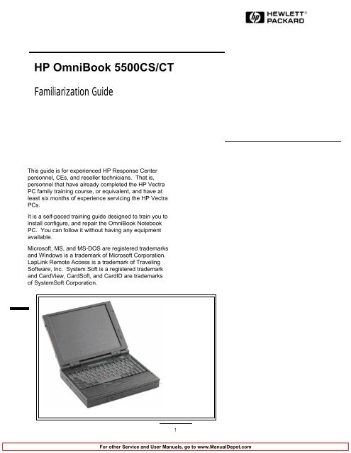
HP OmniBook 5500CS/CT PC Familiarization Guide ... - Elhvb.com
HP OmniBook 5500CS/CT PC Familiarization Guide ... - Elhvb.com
HP OmniBook 5500CS/CT PC Familiarization Guide ... - Elhvb.com

You also want an ePaper? Increase the reach of your titles
YUMPU automatically turns print PDFs into web optimized ePapers that Google loves.
<strong>HP</strong> <strong>OmniBook</strong> <strong>5500CS</strong>/<strong>CT</strong><br />
<strong>Familiarization</strong> <strong>Guide</strong><br />
This guide is for experienced <strong>HP</strong> Response Center<br />
personnel, CEs, and reseller technicians. That is,<br />
personnel that have already <strong>com</strong>pleted the <strong>HP</strong> Vectra<br />
<strong>PC</strong> family training course, or equivalent, and have at<br />
least six months of experience servicing the <strong>HP</strong> Vectra<br />
<strong>PC</strong>s.<br />
It is a self-paced training guide designed to train you to<br />
install configure, and repair the <strong>OmniBook</strong> Notebook<br />
<strong>PC</strong>. You can follow it without having any equipment<br />
available.<br />
Microsoft, MS, and MS-DOS are registered trademarks<br />
and Windows is a trademark of Microsoft Corporation.<br />
LapLink Remote Access is a trademark of Traveling<br />
Software, Inc. System Soft is a registered trademark<br />
and CardView, CardSoft, and CardID are trademarks<br />
of SystemSoft Corporation.<br />
Click on this frame to insert a graphic in this area.<br />
1
Table of Contectnsontents<br />
<strong>OmniBook</strong> Product Comparisons ....................................................................... ........... 3<br />
<strong>OmniBook</strong> 5500 Series: Product Features ........................................................... ........... 7<br />
Notebook Hardware Structure ........................................................................... ......... 21<br />
Removing LCD Assy and Icon Assy ...................................................................... ......... 21<br />
Replacing Disp Panel Plastic, Disp Cover Plastic, Hook, and Hook Button ................. ......... 24<br />
Removal and replacement of Rubber Feet, Plastic Feet, HDD Door, Memory Cover<br />
Door, and RAM Expansion Module. ......................................................................<br />
......... 24<br />
Removal of HDD Drive, FDD Module, CD-ROM Assy, Enhanced Li-Ion Battery,<br />
Standard Li-Ion Battery, Printer Port Door, Expansion Door, and I/O door ...............<br />
......... 26<br />
Removal of Palmrest Assy and Sub Battery Set (4.8V) ............................................. ......... 27<br />
Removal of Keyboard and Power Supply Board (<strong>PC</strong>A PT-DC) ................................. ......... 28<br />
Removal of Upper Chassis Case and Icon <strong>PC</strong>A (<strong>PC</strong>A PT-ICON) ............................. ......... 28<br />
Removal of the Heat Pipe Bracket, Heat Pipe, Heat Pipe Spreader, CPU Module, and<br />
Heat Sink ............................................................................................................<br />
......... 30<br />
Removal of KBD Shielding Plate ........................................................................... ......... 31<br />
Removal of Motherboard (<strong>PC</strong>A PT-586 with I/O Bracket), HDD <strong>PC</strong>B Bracket,<br />
HDD-F<strong>PC</strong> Flex, FFC Cable T/B to M/B 10 Pin, Bezel, IR Lens, and <strong>PC</strong>MCIA<br />
buttons. ..............................................................................................................<br />
......... 32<br />
Configuration and Setup .................................................................................... ......... 33<br />
Main Configuration Screen ................................................................................... ......... 33<br />
Power Screen ...................................................................................................... ......... 34<br />
Power Configuration ............................................................................................ ......... 35<br />
System Configuration ........................................................................................... ......... 36<br />
Input/Output Configuration ................................................................................... ......... 37<br />
Disk Configuration ............................................................................................... ......... 38<br />
Troubleshooting and Repair ............................................................................... ......... 39<br />
Final Quiz .......................................................................................................... ......... 43<br />
2
<strong>OmniBook</strong> Product Comparisons<br />
Size Closed<br />
Weight<br />
Processor<br />
Bus Architecture<br />
Cache<br />
Display<br />
<strong>HP</strong> <strong>OmniBook</strong> 5500<br />
•29.5 x 22.5 x 5.2 cm<br />
(11.6 x 8.8 x 2.05 in)<br />
•3.4 kg (7.5 lb)<br />
•100-, 120-, and<br />
133-MHz Intel Pentium<br />
processor<br />
32-bit <strong>PC</strong>I bus<br />
256-KB external L2<br />
cache<br />
•10.4 and 12.1 - inch<br />
diagonal TFT:<br />
• SVGA (<strong>CT</strong>S): 800 x<br />
600 x 64K colors<br />
(TFT)<br />
11.3 - inch diagonal<br />
DSTN:<br />
SVGA: 800 X 600 X<br />
256 colors<br />
•<strong>PC</strong>I local bus video;<br />
1-MB video RAM<br />
vSVGA-out supports<br />
VGA & SVGA monitors<br />
(up to 1024 x 768 x<br />
256 colors)<br />
<strong>HP</strong> <strong>OmniBook</strong> 5000<br />
•29.5 x 22.6 x 4.9 cm<br />
(11.6 x 8.9 x 1.93 in)<br />
•3.08-3.18 kg (6.8-7 lb)<br />
•75-, 90-, or 120-MHz<br />
Intel Pentium<br />
processor<br />
32-bit <strong>PC</strong>I bus<br />
some models include:<br />
256-KB external L2<br />
cache<br />
•10.4-inch diagonal:<br />
•VGA (C/<strong>CT</strong>): 640 x<br />
480 x 65,536 colors<br />
(DSTN or TFT)<br />
•SVGA (<strong>CT</strong>S): 800 x<br />
600 x 256 colors<br />
(TFT)<br />
•<strong>PC</strong>I local bus video;<br />
1.5-MB video RAM<br />
vSVGA-out supports<br />
VGA & SVGA monitors<br />
(up to 1024 x 768 x<br />
256 colors)<br />
3<br />
<strong>HP</strong> <strong>OmniBook</strong> 4000<br />
v29.5 x 22.6 x 4.9 cm<br />
(11.6 x 8.9 x 1.93 in)<br />
vDSTN (C): 3.13 kg<br />
(6.9 lb)<br />
vTFT (<strong>CT</strong>): 3.27 kg<br />
(7.2 lb)<br />
v50-, 75-, or 100-MHz<br />
Intel 486DX2<br />
ISA bus<br />
No L2 cache<br />
v10.3-diagonal DSTN<br />
(up to 256 colors) or<br />
v10.4-inch diagonal<br />
TFT (up to 65,536<br />
colors)<br />
vVGA: 640 x 480<br />
vLocal bus video;<br />
1-MB display RAM<br />
vSVGA-out supports<br />
VGA & SVGA monitors<br />
(up to 1024 x 768 x<br />
256 colors)
Power<br />
Removable Modules<br />
Mass Storage<br />
RAM<br />
Audio<br />
<strong>HP</strong> <strong>OmniBook</strong> 5500<br />
•14.4Vdc<br />
Rechargeable<br />
Lithium-Ion battery<br />
•Battery life<br />
(approximate with one<br />
battery LiIon): 2 to 3<br />
hrs<br />
•Battery (LiIon)<br />
recharges to high level<br />
in 4 hrs using AC<br />
adapter while <strong>PC</strong> is on<br />
or off<br />
•2-minute low-battery<br />
warning<br />
•AC adapter 100 to<br />
240 Vac (50 to 60 Hz)<br />
input; 12 Vdc, 3.3 A<br />
output<br />
•Instant-on maintains<br />
<strong>com</strong>puter in<br />
ready-to-work state for<br />
weeks on a full charge;<br />
returns you to your<br />
application or file<br />
instantly<br />
•Floppy disk drive<br />
internal/external (can<br />
be replaced with a<br />
second battery CD<br />
ROM drive)<br />
•Hard disk drive<br />
•RAM<br />
•Standard Battery<br />
•810-MB, 1.35-GB,<br />
2.0GB hard disks<br />
v8 or 16-MB Models<br />
•upgradable to 64 MB<br />
•8-, 16-, or 32-MB<br />
RAM cards<br />
•16-bit with Sound<br />
Blaster Pro <strong>com</strong>patible<br />
and MIDI support<br />
•Stereo sound via two<br />
built-in speakers<br />
<strong>HP</strong> <strong>OmniBook</strong> 5000<br />
•14.4Vdc<br />
Rechargeable<br />
Lithium-Ion or NiMH<br />
battery<br />
•Battery life<br />
(approximate with one<br />
battery): 2 to 3 hrs<br />
•Battery recharges to<br />
high level in 4 hrs<br />
using AC adapter while<br />
<strong>PC</strong> is on or off<br />
•2-minute low-battery<br />
warning<br />
•AC adapter 100 to<br />
240 Vac (50 to 60 Hz)<br />
input; 12 Vdc, 3.3 A<br />
output<br />
•Instant-on maintains<br />
<strong>com</strong>puter in<br />
ready-to-work state for<br />
weeks on a full charge;<br />
returns you to your<br />
application or file<br />
instantly<br />
•Floppy disk drive (can<br />
be replaced with a<br />
second battery for<br />
double battery life)<br />
•Hard disk drive<br />
•RAM<br />
•Battery<br />
•540-MB, 810-MB, or<br />
1.2-GB hard disks<br />
v8- or 16-MB Models<br />
•upgradable to 64 MB<br />
•8-, 16-, or 32-MB<br />
RAM cards<br />
•16-bit with Sound<br />
Blaster and MIDI<br />
support<br />
•Stereo sound via two<br />
built-in speakers<br />
4<br />
<strong>HP</strong> <strong>OmniBook</strong> 4000<br />
v14.4 Vdc<br />
rechargeable NiMH<br />
battery pack<br />
vBattery life<br />
(approximate):<br />
3-4 hrs on DSTN<br />
DX2/50<br />
2-3 hrs on TFT<br />
DX4/100<br />
vAC adapter 100 to<br />
240 Vac (50 to 60 Hz)<br />
input; 21 Vdc,1.35 A<br />
output<br />
Suspend-resume<br />
power management.<br />
vFloppy disk drive<br />
(can be replaced with<br />
a second battery for<br />
double battery life)<br />
vHard disk drive<br />
vRAM<br />
vBattery<br />
v260-, 340-, 520-, or<br />
810-MB hard disk<br />
options<br />
v4-, 8-MB, or 16-MB<br />
RAM models<br />
vupgradable to 32 MB<br />
v16-bit, Sound<br />
Blaster-<strong>com</strong>patible<br />
vStereo sound via two<br />
built-in stereo speakers
Input/Output<br />
Expandability<br />
<strong>HP</strong> <strong>OmniBook</strong> 5500<br />
•9-pin, 115,200 - b/s,<br />
RS-232 port<br />
•25-pin EPP and ECP<br />
parallel port<br />
•SVGA-out (up to 1024<br />
x 768 x 256); VGA-out<br />
(640 x 480 x 16M<br />
colors)<br />
• Fast-IR-IRDA<br />
<strong>com</strong>pliant @ 4Mbps<br />
•Expansion bus<br />
connector<br />
•NTSC/PAL video-out<br />
port (RCA and SVideo)<br />
•Keyboard/mouse port<br />
•Headphone/stereo-out<br />
port<br />
•Stereo-in and<br />
microphone ports<br />
•MIDI/joystick port<br />
•One Type III <strong>PC</strong>MCIA<br />
slot (or use as two<br />
Type II slots) with<br />
3.3-V or 5-V support<br />
vOptional docking<br />
system with two<br />
ISA-based slots, or<br />
one ISA and one <strong>PC</strong>I<br />
slot, parallel, serial,<br />
SVGA-out (up to 1024<br />
x 768 x 256),<br />
keyboard, PS/2<br />
mouse, MIDI/joystick,<br />
and audio.<br />
<strong>HP</strong> <strong>OmniBook</strong> 5000<br />
•9-pin, 115,200 - b/s,<br />
RS-232 port<br />
•25-pin EPP and ECP<br />
parallel port<br />
•SVGA-out (up to 1024<br />
x 768 x 256); VGA-out<br />
(640 x 480 x 65,536<br />
colors)<br />
•115,200-baud,<br />
bidirectional infrared<br />
•Expansion bus<br />
connector<br />
•SCSI-2 port<br />
•NTSC/PAL video-out<br />
port<br />
•Keyboard/mouse port<br />
•Headphone/stereo-out<br />
port<br />
•Stereo-in and<br />
microphone ports<br />
•MIDI/joystick port<br />
•One Type III <strong>PC</strong>MCIA<br />
slot (or use as two<br />
Type II slots) with<br />
3.3-V or 5-V support<br />
vOptional docking<br />
system with two<br />
ISA-based slots, or<br />
one ISA and one <strong>PC</strong>I<br />
slot, parallel, serial,<br />
SVGA-out (up to 1024<br />
x 768 x 256),<br />
keyboard, PS/2<br />
mouse, MIDI/joystick,<br />
and audio.<br />
5<br />
<strong>HP</strong> <strong>OmniBook</strong> 4000<br />
v9-pin, 115,200 - b/s,<br />
RS-232 port<br />
v25-pin EPP and ECP<br />
parallel port<br />
vSVGA-out (up to<br />
1024 x 768 x 256)<br />
v115,200 - baud,<br />
bi-directional infrared<br />
vExpansion bus<br />
connector<br />
vKeyboard/mouse port<br />
v<br />
Headphone/stereo-out<br />
port<br />
vMicrophone port<br />
vStereo-in port<br />
vOne Type III<br />
<strong>PC</strong>MCIA slot (or use<br />
as two Type II slots)<br />
vEnhanced port<br />
replicator with parallel,<br />
two serial, SVGA-out<br />
(up to 1024 x768),<br />
keyboard, PS/2<br />
mouse, and SCSI<br />
ports; and <strong>PC</strong>MCIA<br />
slot (concurrent Type II<br />
and Type III)
Pre-installed Software<br />
Security Features<br />
<strong>HP</strong> <strong>OmniBook</strong> 5500<br />
•Microsoft Windows 95<br />
or<br />
vMicrosoft Windows<br />
for Workgroups 3.11 *<br />
•MS-DOS 6.22<br />
•Plug and Play BIOS<br />
•<strong>HP</strong> PIM<br />
• 2-level password<br />
protection<br />
• <strong>PC</strong> ID (tattooing) and<br />
serialization<br />
• Drive lock<br />
• Kensington lock slots<br />
<strong>HP</strong> <strong>OmniBook</strong> 5000<br />
•Microsoft Windows 95<br />
or<br />
vMicrosoft Windows<br />
for Workgroups 3.11 *<br />
•MS-DOS 6.22<br />
•Plug and Play BIOS<br />
•<strong>HP</strong> PIM<br />
•2-level password<br />
protection<br />
•<strong>PC</strong> ID (tattooing)<br />
•Kensington lock slots<br />
6<br />
<strong>HP</strong> <strong>OmniBook</strong> 4000<br />
vMicrosoft Windows<br />
for Workgroups 3.11<br />
vMS-DOS 6.2<br />
vLaplink Remote<br />
Access<br />
vEasy connection to<br />
your desktop <strong>PC</strong>,<br />
network and desktop<br />
printers; works via<br />
cable or infrared.<br />
vUser password<br />
vKensington lock slots
<strong>OmniBook</strong> 5500 Series: Product Features<br />
Description<br />
Models<br />
<strong>HP</strong> <strong>OmniBook</strong> 5500 notebook <strong>PC</strong>s feature industry leading performance with the<br />
powerful <strong>com</strong>bination of Pentium processors and a true <strong>PC</strong>I bus for professionals<br />
who need Pentium desktop-to-go performance.<br />
This is a <strong>com</strong>plete list of all the standard <strong>OmniBook</strong> 5500 models now available.<br />
Factory special options are not included in this listing. New models will continue to<br />
be introduced.<br />
Please refer to the Hewlett-Packard Corporate Price List for currently available<br />
models and options.<br />
Product<br />
<strong>HP</strong> <strong>OmniBook</strong> 5500<strong>CT</strong><br />
<strong>HP</strong> <strong>OmniBook</strong> 5500<strong>CT</strong><br />
<strong>HP</strong> <strong>OmniBook</strong> 5500<strong>CT</strong><br />
<strong>HP</strong> <strong>OmniBook</strong> 5500<strong>CT</strong><br />
<strong>HP</strong> <strong>OmniBook</strong> 5500<strong>CT</strong><br />
<strong>HP</strong> <strong>OmniBook</strong> <strong>5500CS</strong><br />
<strong>HP</strong> <strong>OmniBook</strong> <strong>5500CS</strong><br />
<strong>HP</strong> <strong>OmniBook</strong> <strong>5500CS</strong><br />
<strong>HP</strong> <strong>OmniBook</strong> 5500<strong>CT</strong><br />
<strong>HP</strong> <strong>OmniBook</strong> 5500<strong>CT</strong><br />
Description<br />
P-133, <strong>PC</strong>I BUS, 2.0GB HDD, 16MB RAM,<br />
LiIon Battery, 12.1" SVGA TFT Display,<br />
Three year warranty.<br />
P-133, <strong>PC</strong>I BUS, 1.35GB HDD, 16MB RAM,<br />
LiIon Battery, 12.1" SVGA TFT Display,<br />
Three year warranty.<br />
P-120, <strong>PC</strong>I BUS, 1.35GB HDD, 16MB RAM,<br />
LiIon Battery, 12.1" SVGA TFT Display,<br />
Three year warranty.<br />
P-120, <strong>PC</strong>I BUS, 1.35GB HDD, 16MB RAM,<br />
LiIon Battery, 10.4" SVGA TFT Display,<br />
One year warranty.<br />
P-120, <strong>PC</strong>I BUS, 1.35GB HDD, 16MB RAM,<br />
LiIon Battery, 10.4" SVGA TFT Display,<br />
One year warranty.<br />
P-120, <strong>PC</strong>I BUS, 1.35GB HDD, 16MB RAM,<br />
LiIon Battery, 11.3" SVGA DSTN Display,<br />
One year warranty.<br />
P-100, <strong>PC</strong>I BUS, 1.35GB HDD, 16MB RAM,<br />
LiIon Battery, 11.3 " SVGA DSTN Display,<br />
One year warranty.<br />
P-100, <strong>PC</strong>I BUS, 1.35GB HDD, 8MB RAM,<br />
LiIon Battery, 11.3" SVGA DSTN Display,<br />
One year warranty.<br />
P-100, <strong>PC</strong>I BUS, 810MB HDD, 8MB RAM,<br />
LiIon Battery, 10.4" SVGA TFT Display,<br />
One year warranty.<br />
P-100, <strong>PC</strong>I BUS, 810MB HDD, 8MB RAM,<br />
LiIon Battery, 11.3" SVGA DSTN Display,<br />
One year warranty.<br />
7<br />
<strong>HP</strong> Part #<br />
F1320A<br />
F1321A<br />
F1322A<br />
F1323A<br />
F1324A<br />
F1325A<br />
F1326A<br />
F1327A<br />
F1328A<br />
F1329A
Accessories<br />
<strong>OmniBook</strong> 5500<br />
enhancements over<br />
the <strong>OmniBook</strong><br />
5000.<br />
What <strong>com</strong>es in the<br />
box<br />
Microprocessor<br />
Description<br />
8-MB RAM expansion card<br />
16-MB RAM expansion card<br />
32-MB RAM expansion card<br />
810-MB Hard Disk Drive<br />
1.35 GB Hard Disk Drive<br />
3.5 inch Internal/External Floppy Drive Module<br />
Quad-speed CD-ROM drive<br />
AC Adapter<br />
NiMH Battery Pack Module<br />
Standard LiIon Battery Pack Module<br />
Enhanced LiIon Battery Pack Module<br />
External Battery Charger (Charges up to two batteries concurrently)<br />
Automobile Adapter<br />
Docking system. Includes 2 full-length ISA slots, parallel, serial,<br />
SVGA-out, keyboard, PS/2 mouse, audio, MIDI/Joystick, SCSI-2 ports,<br />
supports PnP and hot docking. Motorized docking to ensure solid<br />
dock. Docking system only for the <strong>OmniBook</strong> 5000<br />
w 133MHz Pentium CPU<br />
w Internal CD ROM Option - 4X Toshiba or Teac drive<br />
w Internal floppy drive can also be used externally using built in cable<br />
w IBM Tracpoint III pointing device replaces the track ball.<br />
Part #<br />
F1134A<br />
F1135A<br />
F1136A<br />
F1191A<br />
F1192A<br />
F1195A<br />
F1319A<br />
F1044B<br />
F1073A<br />
F1193A<br />
F1194A<br />
F1338A<br />
F1064A<br />
F1189A<br />
w Chips and Technologies Inc. (65548) from the 65545 <strong>PC</strong>I bus VGA Controller with<br />
1 MB of display RAM<br />
w SVideo Output Port<br />
w Larger display options (12.1" TFT SVGA and 11.3" STN SVGA)<br />
w VLSI 82C147 fastIR controller and <strong>HP</strong>-OED FastIR optical module.<br />
w Second battery is a "super" battery and has 150% of the capacity of the standard<br />
battery.<br />
w <strong>OmniBook</strong> 5500 mainframe<br />
w Battery pack<br />
w Recovery CD ROM<br />
w AC adapter (P//N: F1044B), localized power cord<br />
w User documentation: Quick Start <strong>Guide</strong>, support documentation,<br />
registration form<br />
w Brochures for <strong>OmniBook</strong> accessories and Deskjet 320<br />
w Intel Pentium, 100 MHz w/16K internal cache and 256K L2 synchronous burst<br />
cache<br />
8
Bus Architecture<br />
Memory and Memory<br />
Slots<br />
Possible Memory<br />
Configurations:<br />
Mass storage<br />
w Intel Pentium, 120 MHz w/16K internal cache and 256K L2 synchronous burst<br />
cache<br />
w Intel Pentium, 133 MHz w/16K internal cache and 256K L2 synchronous burst<br />
cache<br />
<strong>PC</strong>I (Peripheral Component Interconnect)<br />
w 0MB on Board<br />
w Max Possible RAM: 64MB<br />
w 6-3-3-3 burst hit, self refreshed<br />
w Type of memory boards: <strong>HP</strong> Proprietary Daughter boards, 2 user<br />
accessible slots on the bottom case.<br />
w Expansion Memory Board Options:<br />
8-MB RAM, p/n: F1134A<br />
16-MB RAM, p/n: F1135A<br />
32-MB RAM, p/n: F1136A<br />
w RAM Manufacturer: Multiple Vendors: NEC, Samsung, etc.<br />
w Cycle time: 70 ns<br />
Memory Slot 1<br />
8MB<br />
8MB<br />
8MB<br />
8MB<br />
16MB<br />
16MB<br />
16MB<br />
16MB<br />
32MB<br />
Memory Slot 2<br />
--<br />
8MB<br />
16MB<br />
32MB<br />
--<br />
8MB<br />
16MB<br />
32MB<br />
32MB<br />
Total RAM<br />
8MB<br />
16MB<br />
24MB<br />
40MB<br />
16MB<br />
24MB<br />
32MB<br />
48MB<br />
64MB<br />
The hard disk drive can be removed by the user for easy upgrades.<br />
The hard drive is located on the bottom case and with the removal of<br />
one screw the hard drive can be replaced.<br />
w Hard drive manufacturer: Toshiba (Subject to change. IBM and Maxtor are being<br />
looked at as possible second sources.)<br />
2.5" Hard<br />
Drive<br />
810 MB 1,350MB 2.0GB<br />
Recording<br />
Method<br />
Heads<br />
Average seek<br />
(read)<br />
ATA2 Interface<br />
PRML (Partial<br />
Response<br />
Maximum<br />
likelihood)<br />
MR (Magneto<br />
Resistive)<br />
13 ms<br />
9<br />
ATA2 Interface<br />
PRML (Partial<br />
Response<br />
Maximum<br />
likelihood)<br />
MR (Magneto<br />
Resistive)<br />
13 ms<br />
ATA2 Interface<br />
PRML (Partial<br />
Response<br />
Maximum<br />
likelihood)<br />
MR (Magneto<br />
Resistive)<br />
13 ms
2.5" Hard<br />
Drive<br />
Track to track<br />
seek<br />
Full Track<br />
Average<br />
latency<br />
Rotational<br />
speed<br />
Media Transfer<br />
rate<br />
Buffer to host<br />
Buffer size<br />
Spindle start<br />
time<br />
Reliability:<br />
MTBF: 300,000 hours<br />
Power-on<br />
Hours<br />
Unrecoverab 1.0E-14 bits<br />
le errors transfer<br />
Configuration:<br />
Sector Size 512 Bytes<br />
Recording<br />
Zones<br />
8<br />
User<br />
Cylinders<br />
3,660<br />
User<br />
sectors/Trac<br />
k at zone 0<br />
135<br />
Data Heads 4<br />
Disks<br />
3 ms<br />
25 ms<br />
6.1 ms<br />
64KB (read and 64KB (read and<br />
write segmented<br />
buffer)<br />
write segmented<br />
buffer)<br />
3 sec<br />
3 sec 3 sec<br />
2<br />
810 MB<br />
4200 rev/m<br />
38 (inner), 56.0<br />
(Outer) Mbits/sec<br />
16.6Mbytes/sec<br />
3 ms<br />
25 ms<br />
6.1 ms<br />
4200 rev/m<br />
38 (inner), 56.0<br />
(Outer)<br />
Mbits/sec<br />
16.6Mbytes/sec<br />
300,000 hours<br />
1.0E-14 bits<br />
transfer<br />
512 Bytes<br />
8<br />
3,660<br />
135<br />
6<br />
3<br />
1,350MB<br />
2.0GB<br />
3 ms<br />
25 ms<br />
6.1 ms<br />
4200 rev/m<br />
38 (inner), 56.0<br />
(Outer) Mbits/sec<br />
16.6Mbytes/sec<br />
300,000 hours<br />
1.0E-14 bits<br />
transfer<br />
512 Bytes<br />
3,660<br />
135<br />
Note: The hard disk drive can be removed by the user for easy<br />
upgrades. The hard drive is located on the bottom case and with the<br />
removal of one screw the hard drive can be removed.<br />
10<br />
10<br />
5
Center Bay Modules<br />
Built-in I/O<br />
w Floppy Disk Drive:<br />
Internal 3.5 inch, 1.44-MB flexible disk drive is standard on all<br />
models. The flexible disk drive can be easily removed by the user<br />
and replaced with an additional battery pack to double battery life or<br />
with CD ROM Module. The Floppy Disk Drive Modeul has a built in<br />
cable that allows the module to be used externally (through the<br />
parallel port) as well. This allows the Floppy Disk Drive and the CD<br />
ROM to be used at simultaneously.<br />
Manufacturer: Teac<br />
w CD ROM<br />
Internal 4X CD ROM, IDE (ATAPI standard). Unlike the Floppy<br />
Disk Drive Module, the CD ROM Module can not be used<br />
externally.<br />
Manufacturer: Toshiba<br />
Specs:<br />
Transfer Rate: 600K sustained (Burst 8.ssMB/s - Mode3)<br />
Buffer: 128K<br />
Access: 200ms<br />
Seek: 170ms<br />
Modes: CDROM (Mode 1&2), Photo CD, CD Plus, CDXA, CD-I,<br />
Multisession<br />
w LiIon Battery Module<br />
The large LiIon Battery Module has 150% of the capacity of the<br />
standard LiIon battery. It installs in the center bay. This module is<br />
approved as a <strong>com</strong>ponent by UL, CSA, and TUV.<br />
w 9-pin, 115,000-b/s RS-232 port, UART 16550<br />
w 25 pin bi-directional ECP, EPP, and external FDD autosense parallel<br />
port<br />
w SVGA out (up to 1024 x 768 x 256 colors) with simultaneous viewing<br />
VGA out (640 x 480 x 16M colors)<br />
w Fast-IR-IRDA <strong>com</strong>pliant @ 4 Mbps<br />
w Expansion Bus Connector for connecting to the docking station<br />
(includes <strong>PC</strong>I, AT bus and multimedia signals.<br />
w 2 NTSC/PAL ports: 1 RCA, 1 S-Video<br />
w Keyboard/mouse port<br />
w Headphone/stereo-out port<br />
w Microphone port<br />
w Stereo-in port<br />
11
Display/Video<br />
Display/Video<br />
TFT Display Quality<br />
w MIDI/joystick port<br />
Size<br />
Resolution<br />
Video bus, display<br />
RAM<br />
Memory<br />
TFT SVGA<br />
Display<br />
Active Matrix<br />
10.4 inches<br />
diagonal<br />
800 x 600 x 64K<br />
colors @ 60HZ<br />
Refresh: 90ms (18<br />
bit)<br />
32-bit <strong>PC</strong>I bus<br />
1-MB display RAM<br />
EDO<br />
w Display Manufacturer: Hitachi<br />
12.1 inches<br />
diagonal<br />
800 x 600 x 64K<br />
colors @ 60HZ<br />
(18 bit)<br />
TFT SVGA<br />
Display<br />
Active Matrix<br />
32-bit <strong>PC</strong>I bus<br />
1-MB display RAM<br />
EDO<br />
w Video graphics controller chip: Chips and Technologies <strong>CT</strong> 65548<br />
w External video resolution (both types): Supports VGA/SVGA<br />
external monitors with up to 1024 x 768 x 256 colors in noninterlaced<br />
mode. Resolution options:<br />
Resolution<br />
640 x 480<br />
640 X 480<br />
800 x 600<br />
800 X 600<br />
1024 X 768<br />
1024 x 768<br />
Maximum colors<br />
16M<br />
64K<br />
64K<br />
256<br />
64K<br />
256<br />
w DSTN Displays do not support panning modes for 1024 X 768<br />
external and 800 X 600 internal.<br />
w Auto detection of external monitor without rebooting<br />
Note: Includes option to simultaneously display external video and<br />
notebook display.<br />
DSTN Display<br />
Dual Scan<br />
Twisted Nematic<br />
11.3 inches diagonal<br />
640 x 480, 256 or<br />
64K colors @ 60Hz.<br />
Refresh: 160ms (8<br />
bit)<br />
32-bit <strong>PC</strong>I bus<br />
1-MB display RAM<br />
EDO<br />
Refresh<br />
60Hz<br />
75HZ<br />
60Hz<br />
75Hz<br />
60Hz<br />
75HZ<br />
TFT display manufacturing is a high precision but imperfect technology and<br />
manufacturers cannot currently produce large displays that are cosmetically perfect.<br />
Most if not all TFT displays will exhibit some level of cosmetic imperfection. These<br />
cosmetic imperfections may be visible to the customer under varying display<br />
conditions and can appear as bright, dim or dark spots.<br />
This issue is <strong>com</strong>mon across all vendors supplying TFT displays in their products and<br />
is not specific to the <strong>HP</strong> <strong>OmniBook</strong> display.<br />
The <strong>HP</strong> <strong>OmniBook</strong> TFT displays meet or exceed all TFT manufacturer's standards<br />
for cosmetic quality of TFT displays. <strong>HP</strong> does not warrant that the displays will be<br />
free of cosmetic imperfections.<br />
TFT displays may have a small number of cosmetic imperfections and still conform<br />
to the display manufacturers cosmetic quality specifications.<br />
Here are some guidelines to use in determining what action to take on a customer<br />
<strong>com</strong>plaint of cosmetic imperfection in their TFT display:<br />
1. The unit should be viewed in the customer's normal operating condition.<br />
12
TFT Display Quality<br />
(continued)<br />
User interface<br />
Power<br />
Battery Life; rundown<br />
data (approx.):<br />
This means if the customer uses the unit predominately in DOS, or Windows, or in<br />
some other application or <strong>com</strong>bination of applications, that is where the<br />
determination shall be made. Self test is not a normal operating condition and is not<br />
a sufficient tool to interpret display quality.<br />
2. In the customer's normal operating mode:<br />
a. If 4 or more variant pixels appear clustered in the area approximated by a<br />
thumbprint on the display surface, then the display should be considered for<br />
replacement.<br />
b. On <strong>OmniBook</strong> 4000<strong>CT</strong> models, if more than 30 total pixels anywhere on the<br />
display are bad, then the display should be considered for replacement. On<br />
<strong>OmniBook</strong> 600<strong>CT</strong> and <strong>OmniBook</strong> 5000<strong>CT</strong>/5500<strong>CT</strong> models, if more than 15 total<br />
pixels anywhere on the display are bad, then the display should be considered for<br />
replacement.<br />
These are the only conditions in this guideline that may call for a replacement due to<br />
a defect in material or workmanship based on the <strong>HP</strong> Limited Warranty Statement.<br />
3. If a display is considered for replacement, it should be clear to the customer that<br />
cosmetic variations on the replacement display may also exist, and may require the<br />
customer to use a work-around to obscure the cosmetic imperfection.<br />
4. Customers with cosmetic-based <strong>com</strong>plaints only, that do not conform to the above<br />
conditions and tests will not normally be considered for display replacement. It will<br />
be left to the judgment of the <strong>HP</strong>-responsible person who, in working with the<br />
customer, to identify work-arounds that are reasonable and appropriate for the<br />
individual customer. Customers who must have a more perfect display solution<br />
should consider switching to an <strong>OmniBook</strong> with a DSTN display.<br />
We expect over time that the industry will continue to improve in their ability to<br />
produce displays with fewer inherent cosmetic imperfections and will adjust our <strong>HP</strong><br />
guidelines as the improvements are implemented.<br />
wKeyboard: 85/86-key touch-type keyboard with embedded numeric<br />
keypad and 12 Fn keys. Wrist pad provides <strong>com</strong>fort for extended<br />
keyboard use. External 6-pin mini-DIN interface for external keyboard<br />
and/or mouse connection. <strong>OmniBook</strong> 5500 supports the Y connector to<br />
use both the keyboard and mouse. (<strong>HP</strong> external keyboard (101-key)<br />
Part number C3756A)<br />
w Pointing device: IBM Trackpoint III in GBH position.<br />
w Optional pointing devices: Includes 6-pin mini-DIN interface for<br />
external PS/2 mouse connection. Also supports serial mouse<br />
connection.<br />
w Standard Battery types: Removable 14.4-Vdc rechargeable NiMH<br />
and Lithium Ion battery. Both battery types do not require <strong>com</strong>plete<br />
discharge before recharging. There is no "memory" effect that<br />
reduces battery life.<br />
w Large Battery types: Removable 14.4-Vdc rechargeable NiMH and<br />
Lithium Ion battery. Both battery types do not require <strong>com</strong>plete<br />
discharge before recharging. There is no "memory" effect that<br />
reduces battery life.<br />
w The <strong>OmniBook</strong> 5500 batteries are not <strong>com</strong>patible with previous<br />
<strong>OmniBook</strong>s (5000 or 4000).<br />
Battery Type<br />
Standard LiIon<br />
Run Mode<br />
2 - 3 hrs<br />
13<br />
Suspend to RAM<br />
10 days
Battery Life; rundown<br />
data (approx.):<br />
Power<br />
External battery<br />
charger<br />
Automobile adapter<br />
Standard LiIon<br />
battery pack<br />
Battery Type<br />
Large LiIon<br />
<strong>HP</strong> # F1193A<br />
Run Mode<br />
3 - 5 hrs<br />
w <strong>HP</strong> part number: <strong>HP</strong> # F1338A<br />
<strong>HP</strong> # F1064 - same as <strong>OmniBook</strong> 600 and 5000<br />
Suspend to RAM<br />
14 days<br />
w Recharge time (Display off): 4hrs (Standard Li-Ion), 5hs (Lrge<br />
Li-Ion)<br />
w Recharge time (Display on): 5.3hrs (Standard Li-Ion), 6.7 hrs (Large<br />
Li-Ion)<br />
Note: If unit has 1 standard LiIon and 1 large LiIon: 4 hrs +5 hrs = 9<br />
hrs.<br />
w Low battery signals: 2-minute low battery warning. Unit will shut<br />
down if battery warning ignored to ensure data retention.<br />
w Instant on: Maintains <strong>OmniBook</strong> in ready-to-work state for days or<br />
weeks on a full charge; when turned on it returns instantly to previous<br />
state. No waiting for restoring from disk. Ac<strong>com</strong>plished by the use of<br />
self refreshed DRAM technology. Note: The <strong>OmniBook</strong> 5500 utilizes<br />
the same technology as the <strong>OmniBook</strong> 5000 and 600 to achieve the<br />
instant on feature.<br />
w Smart Battery: The <strong>OmniBook</strong> 5500 uses "Smart" battery<br />
technology. The battery itself contains an ASIC (Application Specific<br />
Integrated Circuit) that is able to continuously test and track the status<br />
of the battery. The <strong>OmniBook</strong> BIOS can then receive high-quality<br />
information about the battery condition directly from the hardware and<br />
not interrupt the CPU. The condition can be checked using two<br />
methods that receive information from the BIOS (CONFIGURATION<br />
[fn][f2], Windows Control Panel Power).<br />
w Energy S.T.A.R. <strong>com</strong>pliant<br />
w AC Adapter: 100 to 240 Vac adapter (50 to 60 Hz) input; 12 Vdc, 2.5<br />
A output. Same adapter as the OB600 (F1044B). Use only an <strong>HP</strong><br />
F1044B AC adapter (the type shipped with the <strong>OmniBook</strong>). Using any<br />
other adapter could damage the <strong>OmniBook</strong> and void the warranty.<br />
Always plug it into a grounded outlet.<br />
w Power management options: Advanced; Standard; Off; Custom.<br />
w The <strong>OmniBook</strong> 5500 includes a "fake" off mode while docked. This enables the<br />
user to turn off the OB5500 while docked and not loose any connectivity (such as to<br />
a network). Basically, this mode shuts down the display only and maintains all<br />
power to ports and the CPU.<br />
wA fully charged NiMH battery in storage will loose 20% of its charge per month in<br />
storage.<br />
w Designed for desktop use. Powered by the F1044B adapter<br />
w Charges two additional batteries<br />
w Size: 15.5 x 13.3 x 5.2 cm (estimated), no weight estimate at this date<br />
14
Enhanced LiIon<br />
battery pack<br />
Extra AC adapter<br />
Accessory Slots<br />
Audio Systems<br />
Operating<br />
environment<br />
Storage environment<br />
Environmental<br />
Testing<br />
<strong>HP</strong> # F1194A<br />
<strong>HP</strong> # F1044B<br />
w User available <strong>PC</strong>MCIA Slots: 2 Type II or 1 Type III<br />
w Bus: Intel QuickSwap (ExCa)<br />
w The <strong>PC</strong>MCIA slots are fully industry <strong>com</strong>patible and supports the<br />
latest SystemSoft Card Services and Socket Services. The system<br />
will support a wide variety of <strong>PC</strong>MCIA cards.<br />
w <strong>PC</strong>MCIA controller chip manufacturer: Cirrus Logic (CL-PD6729).<br />
Note: This is fully <strong>com</strong>patible with the Intel 365 chip). Cirrus Logic is<br />
the original <strong>com</strong>pany that developed the <strong>PC</strong>MCIA controller and is<br />
considered the best in the industry.<br />
w High performance audio: 16-bit stereo sound, Sound Blaster hardware <strong>com</strong>patible.<br />
Supports Native Signal Processing (NSP) and is Plug and Play <strong>com</strong>patible.<br />
w Two stereo speakers with acoustic chambers<br />
w I/O: Headphone/stereo-out port; microphone port; Stereo-in port<br />
w IRQ default setting for soundblaster is 5.<br />
w Audio controller and Manufacturer: CS4232, Crystal<br />
w Audio controller characteristics:<br />
sampling: 8-48kzh<br />
playback rate: 8-48kzh<br />
distortion: maximum is 0.02% although you need to consider the type of external<br />
w Temperature: 0 to 35o C (32 to 95o speakers using as these can be a factor in the distortion created.<br />
)<br />
DSTN display models: 41 to 104 degrees F (5 to 40 degrees C)<br />
TFT display models: 50 to 104 degrees F (10 to 40 degrees C)<br />
w 90% relative humidity at 104 degrees F (40 degrees C) maximum<br />
w Temperature: -40 to 149 degrees F (-40 to 65 degrees C)<br />
w 90% relative humidity at 149 degrees F (65 degrees C) maximum<br />
w ESD as per IEC-801-2, EN 55024-2<br />
w Drop testing: 225g, 3ms half sine wave shock: 6 axis, 3 hits per<br />
side.<br />
w Also tests for altitude, magnetic & radiated susceptibility &<br />
interference, shock & vibration.<br />
Note: These are the tests that <strong>HP</strong> designs notebook <strong>com</strong>puters to<br />
meet. Due to normal variations in the <strong>com</strong>ponents of individual<br />
machines, some machines will perform better and some won't perform<br />
as well. <strong>HP</strong> does not garantee that every notebook <strong>com</strong>puter will meet<br />
these specifications.<br />
15
BIOS<br />
Software and<br />
Operating System<br />
Supported Operating<br />
Systems<br />
Security<br />
w Plug and Play BIOS stored in EEPROM<br />
w User Upgradable via floppy drive<br />
w A corrupt BIOS that prevents the machine from booting requires a Motherboard<br />
replacement. The BIOS can be corrupted by interrupting a BIOS upgrade during the<br />
update process.<br />
w Microsoft Windows for Workgroups 3.11 or Windows 95<br />
The <strong>HP</strong> <strong>OmniBook</strong> 5000/5500 family <strong>com</strong>es co-loaded with Windows for Work<br />
Groups and Windows 95. The user selects the operating system of choice<br />
and the other is auto deleted.<br />
w MS-DOS 6.2<br />
wMS DOS version 6.22*<br />
wMicrosoft Windows for Workgroups 3.11*<br />
wMicrosoft Windows 95*<br />
wMicrosoft NT workstation 3.51**<br />
wOS/2 version 3.0**<br />
* Supported to the application level. ** Only setup and configuration supported.<br />
w Physical security from Kensington Lock<br />
w 2 - level password protection (admin and user levels), <strong>PC</strong> ID (tattooing)<br />
16
Password Decode<br />
Password Decode<br />
Policy<br />
If the user forgets the system password, there is a master password that will unlock<br />
the <strong>OmniBook</strong>. The user calls Technical Support to determine this master password<br />
as follows:<br />
1. Support will tell the user the keys to type at the password entry screen ?<br />
2. The <strong>OmniBook</strong> generates and displays an encoded master password. This is<br />
displayed under the normal password entry area. At this point, this is the only<br />
password that will unlock the <strong>OmniBook</strong> unless the user presses [ESC] to remove the<br />
encoded master from the password entry screen. Then the user's stored password<br />
can be entered.<br />
3. The user reads the encoded master password to Support.<br />
4. Support runs a program that decodes the encoded password, and reads the<br />
decoded password (alphanumeric) to the user.<br />
5. The user types in the decoded password.<br />
6. <strong>OmniBook</strong> decodes the encoded master password it generated and <strong>com</strong>pares it to<br />
the decoded password typed in by the user.<br />
7. If the two passwords match, the <strong>OmniBook</strong> is unlocked. The forgotten password is<br />
automatically erased. Support can then guide the user through the process of<br />
entering a new password.<br />
8. If the two passwords do not match, the previous sequence must be repeated until<br />
the user correctly enters a master password.<br />
The encoded master password is an eight-character alphanumeric sequence that the<br />
<strong>OmniBook</strong> generates at random every time the appropriate keys are pressed in the<br />
password entry screen. Because it is generated randomly, a master password can<br />
only be used to unlock the <strong>OmniBook</strong> once. If the user forgets the password at<br />
another time, it will require another call to Support. (If the user presses the<br />
appropriate keys by mistake, pressing [ESC] will allow entering the stored password.)<br />
The password descramble programs for the <strong>HP</strong> <strong>OmniBook</strong> <strong>PC</strong>s are protected as <strong>HP</strong><br />
Company Private information. They may not be copied, backed-up, printed or<br />
distributed. There are only six official copies of each program.<br />
In addition to protecting the program itself, it's use is also controlled.<br />
Hewlett-Packard and authorized support providers must ensure with written evidence<br />
that the <strong>OmniBook</strong> that is being "descrambled" is actually in the hands of the unit's<br />
actual and current owner. This requires a sales receipt showing the unit serial<br />
number and owner's name, or a written statement from the owner attesting that they<br />
are the owner of the unit. The statement can be a FAX copy of the document. The<br />
fact that the unit is in the hands of an <strong>HP</strong> representative on the behalf of the<br />
customer is not evidence of ownership. In addition, <strong>HP</strong> will not descramble a unit for<br />
any non-owner, even if it involves law enforcement agencies. If you receive such a<br />
request, you should notify management and <strong>HP</strong> Corporate Legal immediately.<br />
(These requests may require a court order prior to our participation.)<br />
Further, you must log the name, serial number and date of the running of the<br />
descramble program, and file the written backup with the log. The log and backup is<br />
subject to standard record's retention process and review.<br />
The final issue relating to descramble of passwords is that <strong>HP</strong> cannot provide<br />
information to users that would assist them in improperly descrambling a password<br />
and opening a unit.<br />
17
Notebook Hardware Structure<br />
The following guidelines apply to all subassembly level repairs<br />
w Properly ground yourself and your work area to prevent damage from static discharge<br />
w Always replace any conductive sponge material or thermal tape that be<strong>com</strong>es damaged during repairs.<br />
w Use a #0 Phillips screwdriver to remove all screws<br />
Field Replaceable Assemblies<br />
Removing LCD Assy and Icon Assy (Hewlett-Packard Authorized Service Providers Only)<br />
The LCD Assy and/or Icon Assy on the <strong>OmniBook</strong> <strong>5500CS</strong> and <strong>CT</strong> are removed the same way as on the <strong>OmniBook</strong> 5000. Turn the unit over,<br />
raise the feet, and withdraw the two Phillips screws (screw - display) from under the feet in the bottom back corners of the unit (see diagram<br />
below which shows the <strong>OmniBook</strong> 5000).<br />
18
Turn the unit right side up and dislodge the Icon Assy by placing the thumbs on each edge of the Assy and pushing lightly (see diagram below<br />
which also shows the <strong>OmniBook</strong> 5000). The front edge of the Icon Assy will lift up slightly.<br />
19
Lift the LCD Assy straight up about 1 inch. The Icon Assy will lift up with the display. Move the Icon Assy out of the way. The cable from the<br />
Icon Assy to the <strong>PC</strong>A PT-ICON does not need to be removed if only the LCD Assy is being removed. Otherwise, slide the connector sleeve up to<br />
remove the Icon Assy cable.<br />
If only the Icon Assy is to be removed, the LCD Assy may be lowered back into position.<br />
To remove the LCD Assy, remove the two cables attaching the LCD Assy to the <strong>PC</strong>A PT-ICON . Lastly, remove the two screws attaching the<br />
grounding straps to the <strong>PC</strong>A PT-ICON. The LCD Assy can now be removed the rest of the way.<br />
Notice that the display cabling assembly on the <strong>OmniBook</strong> 5500 is different than on the <strong>OmniBook</strong> 5000. The LCD Assy is not transferable<br />
between the two models.<br />
To reinstall the LCD Assy or Icon Assy, just reverse the above procedure. When reinstalling the LCD Assy, make sure that the two posts on<br />
either side of the Assy line up parallel with their slots in the top case. If they are not parallel, the post will get caught inside the top case<br />
before the display is seated <strong>com</strong>pletely. If this happens, remove the display and line the posts up properly.<br />
20
Replacing Disp Panel Plastic, Disp Cover Plastic, Hook, and Hook Button<br />
Remove four rubber 'feet' from the inside of the LCD Assy. Remove four Phillips screws from under the rubber 'feet". Remove the contrast and<br />
brightness control knobs (TFT displays only have on knob). Firmly pull panel apart as shown in the diagram below. Display panel plastic can<br />
now be replaced.<br />
To replace hook, first remove spring. Then remove outer button by <strong>com</strong>pressing tabs on inside of hook and prying button out. Hook can now<br />
be removed.<br />
To replace Disp Cover plastic, remove LCD Panel, both LCD <strong>PC</strong>Bs, clutch assemblies, and hooks. Replace these items in the new Disp Cover.<br />
21
Removal and replacement of Rubber Feet, Plastic Feet, HDD Door, Memory Cover Door, and RAM<br />
Expansion Module.<br />
Rubber feet are secured to the Lower Chassis Case with adhesive. To remove just pry off. To replace, use attached adhesive.<br />
Plastic feet are removed by <strong>com</strong>pressing the two plastic tabs in the hinge area and pulling the tab out. Reverse the procedure to replace.<br />
The HDD security cover is secured by the one black Phillips Screw - HDD Door. Remove this screw to remove the door. This door must be<br />
removed to remove the HDD Drive.<br />
The Memory Cover Door can be removed by pulling up on the Door with a fingernail placed in the recess on the Lower Chassis Case.<br />
Ram Expansion Modules are removed by pulling on the tabs next to the module. RAM Expansion Modules are end user replaceable.<br />
22
Removal of HDD Drive, FDD Module, CD-ROM Assy, Enhanced Li-Ion Battery, Standard Li-Ion Battery,<br />
Printer Port Door, Expansion Door, and I/O door<br />
To remove HDD Drive, first remove the HDD Door (see instructions on previous page). Once HDD Door is removed, HDD Drive can be<br />
withdrawn from the front of the machine. The HDD Drive is user replaceable.<br />
To remove the FDD Module, CD-ROM Assy or the Enhanced Li-Ion Battery, slide the knurled level on the front of the module to be removed to<br />
the right (when looking at the unit from the front). Pull straight out on the level that is released. The FDD Module, CD-ROM Assy and the<br />
Enhanced Li-Ion Battery are user replaceable.<br />
To remove the Printer Port Door, Expansion Door, or I/O Door, bow the door in the middle until the hinges on each edge clear the recess in<br />
the Lower Chassis Assembly. Reverse<br />
the procedure to install the doors.<br />
24
Removal of Palmrest Assy and Sub Battery Set (4.8V)<br />
To remove the Palmrest Assy, first follow the instructions above to remove the HDD Drive, Center Bay Module (FDD Module, CD-ROM Assy, or<br />
Enhanced Li-Ion Battery) and the Standard Li-Ion Battery. From the bottom of the unit, remove the four screws (Screw CPU M2.6 X 6L). Turn<br />
unit right side up and place a thin flat instrument under the edge of the Palmrest Assy and pry up. The Palmrest Assy will snap up.<br />
Lay the Palmrest Assy upside down on the keyboard. Slip the connector sleeves forward on the ribbon cable connectors on the underside of<br />
the Palmrest and remove the ribbon cable. To remove the Sub Battery Set, remove the tape that holds the wires to the Upper Chassis case.<br />
Next, remove the Sub Battery Set connector from the Palmrest Assy.<br />
Reverse the procedure to reassemble.<br />
25
Removal of Keyboard and Power Supply Board (<strong>PC</strong>A PT-DC)<br />
To remove the Keyboard and <strong>PC</strong>A PT-DC, first follow the instructions above to remove the HDD Drive, Center Bay Module (FDD Module,<br />
CD-ROM Assy, or Enhanced Li-Ion Battery), Standard Li-Ion Battery, and the Palmrest Assy. Remove the four screws (Screw - Keyboard) from<br />
the front edge of the keyboard. The keyboard then lifts up and rotates backward around the two ribbon cables that connect it to the <strong>PC</strong>A<br />
PT-DC. Remove the <strong>PC</strong>A PT-DC by pulling up on the tabs on either side of the <strong>PC</strong>A PT-DC. Separate the Keyboard and the <strong>PC</strong>A PT-DC by<br />
sliding the sleeves forward on the two ribbon cable connectors on the <strong>PC</strong>A PT-DC and withdrawing the cables.<br />
Reverse the procedure reassemble.<br />
26
Removal of Upper Chassis Case and Icon <strong>PC</strong>A (<strong>PC</strong>A PT-ICON)<br />
To remove the Upper Chassis Case and <strong>PC</strong>A PT-ICON, first follow the instructions above to remove the HDD Drive, Center Bay Module (FDD<br />
Module, CD-ROM Assy, or Enhanced Li-Ion Battery), Standard Li-Ion Battery, Palmrest Assy, Keyboard and <strong>PC</strong>A PT-DC. Remove the one<br />
screw (Screw - CPU M2 X 4L) on the left side of the Upper Chassis Case. Upper Chassis Case can then be snapped off. If necessary the<br />
suspend/resume button assembly (PA PT-TRP), which <strong>com</strong>es with the Upper Chassis Case repair part, can be removed by removing the two<br />
screws.<br />
Remove the one screw (Screw - CPU M2 X 4L) holding the <strong>PC</strong>A PT-ICON down. Pull straight up on the <strong>PC</strong>A PT-ICON to remove it.<br />
Reverse the procedure to reassemble. Make sure microphone fits in the recess in the Upper Chassis Case on reassembly.<br />
27
Removal of the Heat Pipe Bracket, Heat Pipe, Heat Pipe Spreader, CPU Module, and Heat Sink<br />
To remove the Heat Pipe Bracket, Heat Pipe, Heat Pipe Spreader, CPU Module, and Heat Sink, first follow the instructions above to remove the<br />
HDD Drive, Center Bay Module (FDD Module, CD-ROM Assy, or Enhanced Li-Ion Battery), Standard Li-Ion Battery, Palmrest Assy, Keyboard,<br />
<strong>PC</strong>A PT-DC, Upper Chassis Case, and <strong>PC</strong>A PT-ICON. Remove the one screw (Screw - CPU M2 X 4L) from the Heat Pipe Bracket and remove the<br />
two screws (Screw - CPU M2 X 4L) from the Heat Pipe Spreader. Now the Heat Pipe Bracket, Heat Pipe, and Heat Pipe Spreader can all be<br />
removed.<br />
Remove the four screws (Screw - CPU M2 X 4L) from the corners of the CPU Module. The three screws in the center of the module should not<br />
be removed. Lift straight up on the CPU Module to remove.<br />
To remove the Heat Sink, remove the two screws (Screw ISOT M2.6 X 4L) in the Heat Sink.<br />
28<br />
Reverse the<br />
above<br />
procedure<br />
to<br />
reassemble.
Removal of KBD Shielding Plate<br />
To remove the KBD Shielding Plate, first follow the instructions above to remove the HDD Drive, Center Bay Module (FDD Module, CD-ROM<br />
Assy, or Enhanced Li-Ion Battery), Standard Li-Ion Battery, Palmrest Assy, Keyboard, <strong>PC</strong>A PT-DC, Upper Chassis Case, <strong>PC</strong>A PT-ICON Heat Pipe<br />
Bracket, Heat Pipe, Heat Pipe Spreader, CPU Module, and Heat Sink.<br />
Remove the five screws (Screw ISOT M2 X 6L) that hold the KBD Shielding Plate down.<br />
Reverse the procedure to replace KBD Shielding Plate.<br />
29
Removal of Motherboard (<strong>PC</strong>A PT-586 with I/O Bracket), HDD <strong>PC</strong>B Bracket, HDD-F<strong>PC</strong> Flex, FFC Cable<br />
T/B to M/B 10 Pin, Bezel, IR Lens, and <strong>PC</strong>MCIA buttons.<br />
The <strong>PC</strong>MCIA buttons can be removed at any stage of the disassembly process. They must, however, be removed before removing the<br />
motherboard.<br />
To remove the Motherboard (<strong>PC</strong>A PT-586 with I/O Bracket), HDD <strong>PC</strong>B Bracket, HDD-F<strong>PC</strong> Flex, FFC Cable T/B to M/B 10 Pin, Bezel, IR Lens,<br />
first follow the instructions above to remove the HDD Drive, Center Bay Module (FDD Module, CD-ROM Assy, or Enhanced Li-Ion Battery),<br />
Standard Li-Ion Battery, Palmrest Assy, Keyboard, <strong>PC</strong>A PT-DC, Upper Chassis Case, <strong>PC</strong>A PT-ICON Heat Pipe Bracket, Heat Pipe, Heat Pipe<br />
Spreader, CPU Module, Heat Sink and KBD Shielding Plate.<br />
The HDD <strong>PC</strong>B Bracket, the HDD-F<strong>PC</strong> Flex, and the FFC Cable T/B to M/B 10 Pin can all be removed without removing the <strong>PC</strong>A PT-586. When<br />
removing the HDD-F<strong>PC</strong> Flex be sure to pull straight up on the connector, sideways pressure can damage or break the connector pins requiring<br />
a full motherboard replacement..<br />
To Remove the Motherboard (<strong>PC</strong>A PT-586 with I/O Bracket), remove the three screws (two are ISOT M2 X 6L and one is an ISOT M2 X 4L) that<br />
hold the <strong>PC</strong>A PT-586<br />
in place. Remove the<br />
two standoffs (notice<br />
that one is 11.75mm<br />
long and the other is<br />
15mm long). Remove<br />
the Dock Grounding<br />
Spring Plate. Remove<br />
the two <strong>PC</strong>MCIA<br />
buttons. Make sure<br />
that you have removed<br />
all RAM expansion<br />
modules. Then lift the<br />
<strong>PC</strong>A straight up. The<br />
I/O Bracket <strong>com</strong>es as<br />
part of the <strong>PC</strong>A<br />
PT-586. If only the I/O<br />
Bracket is damaged, it<br />
can be ordered<br />
separately and<br />
replaced by removing<br />
the 4 standoffs and<br />
two screws from the<br />
back of the bracket.<br />
30
Configuration and Setup<br />
Main Configuration Screen<br />
Pressing [fn][f2] invokes the BIOS setup and configuration utility. The screens shown in this section of the familiarization guide are from the<br />
<strong>OmniBook</strong> 5000. The <strong>OmniBook</strong> 5500 is the same except in the few cases noted in the text.<br />
Users can check system configuration and change settings using [f] keys from this screen. This is the most accurate place to check battery<br />
and system status. Pressing [f3] from this screen exits back to the current application. The setup/configuration utility is operating system<br />
independent. The main screen also displays the BIOS revision in the upper bar.<br />
31
Power Screen<br />
The power screen contains the current power level of the main and auxiliary battery. The auxiliary battery charge status does not show up if no<br />
auxiliary battery is installed. Power conservation settings consists of the options shown which allow customer selection of "Turn OFF" (instant<br />
off), "Auto Save-to-disk", "HDD power-down", and "CPU power-down".<br />
32
Power Configuration<br />
To implement the power management capabilities, the following settings are set by the user from the power setup screen.<br />
Setting:<br />
Power Saving<br />
Turn OFF<br />
Auto Save-to-disk<br />
HDD power-down<br />
CPU power-down<br />
Parameters:<br />
Off/On<br />
Disable/Time<br />
(1 - 30 minutes or never)<br />
Disable/Time<br />
(6 hours to 7 days or never)<br />
Disable/Time<br />
(1-30 minutes or never)<br />
512ms-8seconds<br />
Default:<br />
On<br />
3 minutes<br />
1 day<br />
3 minutes<br />
2 sec<br />
33<br />
Comments:<br />
Enables power saving<br />
techniques.<br />
How long the system will<br />
stay in Run with (no<br />
activity). If disabled it will<br />
stay in Run.<br />
How long the system will be<br />
in off before the entire state<br />
of the <strong>com</strong>puter the<br />
suspend state. If disabled<br />
it will stay in the suspend<br />
state.<br />
HDD will turn off, system<br />
has ability to run. HDD will<br />
spin up when access<br />
required.<br />
CPU clock rate will be<br />
reduce if the system has<br />
been idle for the selected<br />
delay. The clock rate will<br />
be restored when system<br />
activity is detected.
System Configuration<br />
The system screen contains the processor and memory information for the user to glance at. It also allows the user to set the date and time.<br />
The real time clock is not changed until the user exits the setup program. The user can also enable or disable the processor cache.<br />
When the user decides to enable a password, a pop up window requests the old password, new password and confirmation of the new<br />
password. Hard drives or mass storage are not affected by the password--only the turn-on condition.<br />
34
Input/Output Configuration<br />
Setting:<br />
COM Ports<br />
LPT Port<br />
LPT Type<br />
Keyboard Setup<br />
External Devices<br />
Audio Ports<br />
Parameters:<br />
Serial Port (None, COM1 - COM4)<br />
and I/R Port ( None, COM1-<br />
COM4)<br />
None/LPT1, Addr 378/ LPT2, Addr<br />
278/ LPT3, Addr3BC<br />
Bi-directional (PS-2)/Standard AT<br />
(Centronics)<br />
Key Delay (1/4 - 1sec) and Key<br />
Repeat Rate (2cps - 30csp)<br />
VGA Display Device, Television<br />
type<br />
Audio volume, Beeper volume<br />
Default:<br />
Serial Port: COM1, Addr 3F8, IRQ 4<br />
I/R Port: COM2, Addr 2F8, IRQ 3<br />
LPT1, Addr 378<br />
Bi-directional<br />
Key Delay 1/2 sec, Key Repeat Rate<br />
10CPS<br />
VGA Display Device - external VGA if<br />
attached, LCD off. Television type:<br />
NTSC on option ABA units.<br />
Audio volume: ? Beeper Volume: 3<br />
35<br />
Comments:
Disk Configuration<br />
Setting:<br />
Floppy Disk Drive Diskette A<br />
Hard Disk Drive<br />
Parameters:<br />
None, 1.44MB, 2.88MB<br />
Disk Type: None, Standard,<br />
Custom, Auto-ID<br />
Default:<br />
1.44MB<br />
Auto-ID<br />
36<br />
Comments:<br />
Also reports disk drive data (#<br />
cylinders, # heads, sectors/tracks,<br />
landing zone, write pre<strong>com</strong>p)
Troubleshooting and Repair<br />
Known Hardware<br />
Issues<br />
<strong>OmniBook</strong><br />
Self-Test<br />
w The <strong>OmniBook</strong> 5500 is the first <strong>OmniBook</strong> to incorporate drive lock. Drive lock<br />
locks the IDE interface on the hard disk drive so that the drive can not be removed<br />
from one <strong>OmniBook</strong> and read in another <strong>OmniBook</strong>. Both the IBM and Toshiba Hard<br />
Disk Drives that ship with the <strong>OmniBook</strong> 5500 incorporate this feature.<br />
Once a user sets the User Password in the SCU, the <strong>OmniBook</strong> automatically<br />
transfers that password to the hard disk drive in the unit. If the hard disk drive is put<br />
in another unit, the password of the new <strong>OmniBook</strong> must be changed to match the<br />
password set on the drive in order to access the drive.<br />
If the User Password does not match the drive lock password, a message will be<br />
displayed warning that the drive could not be unlocked because of an incorrect<br />
password. :<br />
A drive failure will not display the drive lock error message.<br />
If the unit still functions, insure that the user removes the user password before<br />
returning the product for repair.<br />
w The <strong>com</strong>plete self-test procedure is documented in the <strong>OmniBook</strong> 5500 Operating<br />
<strong>Guide</strong>.<br />
37
First POST: BEEP<br />
CODES<br />
First POST: BEEP<br />
CODES<br />
w A note about interpreting self-test results.<br />
Self-test alone should not be used to diagnose a hardware problem. If the self-test<br />
results are absolutely clear and repeatable, confirm the results with at least two other<br />
non-self-test failure symptoms.<br />
w The <strong>OmniBook</strong> 5500 BIOS includes a POST facility that tests a number of<br />
hardware and firmware items in the unit at each cold-start (BOOT or RESET).<br />
These multiple beep codes indicate a failure in a simple test of:<br />
w a portion of base memory<br />
w Flash BIOS checksum<br />
w a portion of conventional memory<br />
w a portion of extended memory<br />
w If the unit fails to boot:<br />
all accessories are removed, including memory cards, external floppy, port expander,<br />
modems, <strong>PC</strong>MCIA cards, LAN cards, printers, VGA-out cables, external pointing<br />
devices, clean AC power is provided (no "chained" battery chargers or auto<br />
adapters), and press reset.<br />
If the unit still fails to boot, it requires service.<br />
w Beep codes<br />
Beep codes are used to identify a POST error that occurs when the screen is not<br />
available. Once the screen is operating, diagnostic messages are reported to the<br />
screen. There are beep codes for both fatal and nonfatal system board errors.<br />
38
Beep Code<br />
S-S-S-P-S-S-L-P<br />
S-S-S-P-S-L-S-P<br />
S-S-S-P-S-L-L-P<br />
S-S-S-P-L-S-S-P<br />
S-S-S-P-L-S-L-P<br />
S-S-S-P-L-L-S-P<br />
S-S-S-P-L-L-L-P<br />
S-S-L-P-S-S-S-P<br />
S-S-L-P-S-S-L-P<br />
Last POST:<br />
DISPLAY CODES<br />
Description<br />
The DMA page registers are faulty.<br />
The refresh circuitry is faulty<br />
The ROM checksum is incorrect<br />
The CMOS RAM test failed<br />
The DMA controller is faulty<br />
The interrupt controller failed<br />
The 8042 keyboard controller failed<br />
No video adapter was found<br />
No RAM installed. No message is dispalyed.<br />
wThere are a number of POST tests that are performed after the BEEP Code tests.<br />
Failure of one or more of these tests will result in a displayed failure code (i.e.,<br />
03044). It is extremely important not to interpret a failure code immediately as a<br />
hardware failure until:<br />
all accessories are removed, including memory cards external floppy, port expander,<br />
modems, <strong>PC</strong>MCIA cards, LAN cards, printers, VGA-out cables, external pointing<br />
devices, clean AC power is provided (no "chained" battery chargers or auto<br />
adapters), and press reset.<br />
If the unit still fails to boot, it requires service.<br />
NOTE: make sure the display is adjusted to be visible.<br />
39
PhoenixBIOS POST<br />
Messages (Power<br />
On Self Test<br />
Message<br />
CLOCK NOT TICKING CORRE<strong>CT</strong>LY<br />
COLOR/MONO SWITCH INCORRE<strong>CT</strong><br />
CMOS CHECKSUM INVALID - RUN SCU<br />
CMOS FAILURE - RUN SCU<br />
FLOPPY CONTROLLER FAILED<br />
FLOPPY DISK TRACK 0 FAILED<br />
FLOPPY INFORMATION INVALID - RUN SCU<br />
HARD DISK CONTROLLER ERROR<br />
KEYBOARD FAILURE<br />
MACHINE IS LOCKED - TURN KEY<br />
NO INTERRUPTS FROM TIMER 0<br />
Within POST, there are three kinds of messages:<br />
Error messages: These messages appear when there is a failure in hardware,<br />
software, or firmware.<br />
Informational messages: These messages provide information to the user but require<br />
no action.<br />
Beep codes: This kind of warning sounds when POST errors occur and the screen is<br />
not available.<br />
Because the <strong>OmniBook</strong> cannot be repaired by a service center below the FRU level,<br />
these messages will provided limited troubleshooting or repair information. However,<br />
the support specialist and service technician will be able to identify trends in repairs<br />
from these codes.<br />
HARDWARE INFO DOES NOT MATCH VIDEO<br />
CARD - RUN SCU<br />
KEYBOARD CONTROLLER FAILURE<br />
NO BOOTABLE FLOPPY DRIVE 0 INSTALLED<br />
Possible Cause<br />
The real time clock is not ticking.<br />
The COLOR/MONO switch on the system board is<br />
incorrect for the installed hardware.<br />
CMOS RAM information has been corrupted and<br />
needs to be reinitialized via the System Configuration<br />
Utility.<br />
CMOS RAM has lost power and needs to be<br />
reinitialized via the System Configuration Utility.<br />
The floppy controller failed to respond to the reset<br />
<strong>com</strong>mand. Power down the system and check all<br />
appropriate connections. It the floppy controller<br />
contines to fail, you may need to replace it.<br />
The floppy drive cannot read track 0 of the floppy disk<br />
in the drive. Try another diskette. If the problem<br />
persists, you may need to replace the floppy drive.<br />
The drive parameters stored in CMOS do not match<br />
the floppy drives detected in the system.<br />
The hard disk controller failed to respond to the reset<br />
<strong>com</strong>mand. Possible solutions: 1) Check the drive<br />
parameters. 2) Power down the system and check all<br />
appropriate connections. If the problem persists, you<br />
may need to replace the hard disk controller.<br />
The video adapter type specified in CMOS RAM does<br />
not match the installed hardware.<br />
The keyboard failed the self-test <strong>com</strong>mand. Check to<br />
see if the keyboard controller is properly installed. If<br />
the problem continues, replace the controller.<br />
The keyboard failed to respond to the RESET ID<br />
Command.<br />
The system will not continue the boot sequence until<br />
you insert the key into the key lock and turn it.<br />
No bootable floppy drive was detected. Possible<br />
solutions: 1) Power down the system and check all<br />
appropriate connections, cables, etc. 2) In<br />
configurations where no floppy drive is installed, run<br />
System Configuration Utility and make sure the<br />
diskette drive configuration item is set to "None". 3)<br />
Replace the diskette drive if necessary.<br />
The periodic timer interrupt is not occurring.<br />
40
Message<br />
RAM PARITY ERROR AT LOCATION xxxx<br />
ROM AT xxxx (LENGTH YYYY) WITH NON-ZERO<br />
CHECKSUM (zz)<br />
TIME/DATE CORRUPT - RUN SCU<br />
UNEXPE<strong>CT</strong>ED AMOUNT OF MEMORY - RUN SCU<br />
CMOS RAM TEST FAILED<br />
DMA CONTROLLER FAULTY<br />
FAULTY DMA PAGE REGISTERS<br />
FAULTY REFRESH CIRCUIT<br />
INTERRUPT CONTROLLER FAILED<br />
ROM CHECKSUM INCORRE<strong>CT</strong><br />
Possible Cause<br />
A RAM parity error occurred at the specified<br />
(hexadecimal) location.<br />
An illegal adapter ROM was located at the specified<br />
address. An external adapter (such as a video card)<br />
may be causing a conflict.<br />
The time and date stored in the real time clock have<br />
be corrupted, possibly by a power loss.<br />
The amount of memory detected by POST does not<br />
match the amount specified in CMOS RAM.<br />
A walking buit test of CMOS RAM locations 0E (Hex) -<br />
3F (Hex) failed.<br />
A sequential read/write of the transfer count and<br />
transfer address registers within the primary and<br />
secondary DMA controllers failed.<br />
A walking bit read/write of the 16 DMA controller page<br />
registers starting at location 80 Hex failed.<br />
A continuous read/write test of port 61h found that bit<br />
4 (Refresh Detect) failed to toggle within an allotted<br />
amount of time.<br />
A sequential read/write of various Interrupt Controller<br />
registers failed.<br />
A checksum of the ROM BIOS does not match the<br />
byte value at F000:FFFF.<br />
41
Final Quiz<br />
1. What is the bus architecture of the <strong>OmniBook</strong> 5500?<br />
2. What are the three types of displays on the 5500?<br />
3 How can one tell which model has which display?<br />
4. What size level 2 cache does the <strong>OmniBook</strong> 5500 have?<br />
5. Can the level 2 cache be disabled?<br />
6. How do you get to the configuration screens at boot time?<br />
7. How do you get to the configuration screens from Windows?<br />
8. What other <strong>OmniBook</strong> products share the same AC power adapter with the <strong>OmniBook</strong> 5500?<br />
9 What are the user replaceable subassemblies in the <strong>OmniBook</strong> 5500?<br />
10. What is the first POST and how do you decipher the output?<br />
11 What are the three types of messages in the self test?<br />
12. What is the TFT display quality?<br />
13 What do you do if a customer forgets their password?<br />
14. What happens if the drive lock password doesn't match the user password?<br />
15. Can the <strong>OmniBook</strong> 5000 and <strong>OmniBook</strong> 5500 displays be interchanged?<br />
42
<strong>HP</strong> <strong>OmniBook</strong> 5000 Course Evaluation form<br />
43