Gas turbine control Torsten Strand
Gas turbine control Torsten Strand
Gas turbine control Torsten Strand

Create successful ePaper yourself
Turn your PDF publications into a flip-book with our unique Google optimized e-Paper software.
©Siemens Power Generation 2003. All Rights Reserved<br />
Industrial <strong>Gas</strong> <strong>turbine</strong> <strong>control</strong><br />
<strong>Torsten</strong> <strong>Strand</strong><br />
25/04/2006<br />
Power Generation 1
Content<br />
• Introduction to the gas <strong>turbine</strong> and its applications<br />
• <strong>Gas</strong> <strong>turbine</strong> types<br />
©Siemens Power Generation 2003. All Rights Reserved<br />
• Control system tasks<br />
• sequencing<br />
• start & stop<br />
• fuel change over gas to oil and vv, load shedding<br />
• <strong>control</strong><br />
• load or speed = fuel <strong>control</strong><br />
• max power<br />
• emissions<br />
• protection<br />
• risk for personal injuries (explosion, fire, flying objects)<br />
• engine failures<br />
• maintenance<br />
• remaining life<br />
• remote <strong>control</strong> & condition monitoring<br />
25/04/2006<br />
Power Generation 2
GT application Review (1),<br />
offshore & marine<br />
©Siemens Power Generation 2003. All Rights Reserved<br />
GD & MD<br />
BP Ula<br />
Fast Ferry, 60 knots<br />
FPSO<br />
Leadon Field<br />
Buquebus, 450 persons & 50 cars<br />
25/04/2006<br />
Power Generation 3
Application Review (2),<br />
land based<br />
Combined Cycle<br />
©Siemens Power Generation 2003. All Rights Reserved<br />
Simple Cycle<br />
Co-Generation<br />
City of Redding, CA, USA<br />
Gendorf, Germany<br />
25/04/2006 City of Chaska, MN, USA<br />
Power Sandreuth, Generation Germany<br />
4
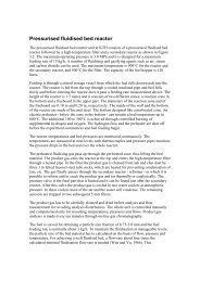
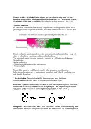
SGT-800, Industrial gas <strong>turbine</strong><br />
Nominal capability, performance and emissions:<br />
©Siemens Power Generation 2003. All Rights Reserved<br />
• SC Output: 45 MW, ISO<br />
• SC Efficiency: 37% (9224 Btu/kWh)<br />
• CC Output: 64 MW, ISO<br />
• CC Efficiency is 53% (6440 Btu/kWh)<br />
• NOx 15 ppmv and CO 5 ppmv, gas fuel (dry)<br />
• NOx 25 ppmv and CO 5 ppmv, liquid fuel (dry<br />
The industrial gas <strong>turbine</strong> is delivered as a complete<br />
package including all systems for its operation<br />
Power Generation 5
The gas <strong>turbine</strong> core flows SGT-600<br />
©Siemens Power Generation 2003. All Rights Reserved<br />
• A gas <strong>turbine</strong> is an air breathing engine, operating with a surplus of air (only 30%<br />
of the Oxygen is used for combustion)<br />
• the air is compressed and heated in the compressor<br />
• fuel is added in the combustor, combustion at constant pressure<br />
• the hot gas is expanded in<br />
• the compressor <strong>turbine</strong>, which drives the compressor<br />
• the power <strong>turbine</strong>, which drives the compressor or generator<br />
25/04/2006<br />
Power Generation 6
The gas <strong>turbine</strong> secondary flows SGT-600<br />
• The gas temperatures in the combustor and the <strong>turbine</strong> inlet stages is higher<br />
than the melting point of the material in spite of the fact that it is of high<br />
temperature Ni-based alloy type<br />
• compressor air is used to cool the combustor walls and the hollow blades of<br />
the first two stages<br />
©Siemens Power Generation 2003. All Rights Reserved<br />
Bleed flows at start<br />
Combustor bypass flow<br />
for emission <strong>control</strong><br />
25/04/2006<br />
Cooling flows<br />
Power Generation 7
SGT-600 DLE Thermal Block<br />
©Siemens Power Generation 2003. All Rights Reserved<br />
SGT-600 is a twin shaft 24 MWe gas <strong>turbine</strong> used for electric<br />
power generation and compressor drive. The compressor has<br />
10 stages, compressor <strong>turbine</strong> 2 stages and power <strong>turbine</strong> 2<br />
stages.<br />
25/04/2006<br />
Power Generation 8
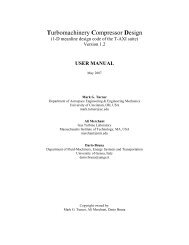
SGT-800 Core engine<br />
©Siemens Power Generation 2003. All Rights Reserved<br />
45 MW single shaft unit, running at 6000 rpm<br />
25/04/2006<br />
15 stage compressor, pressure ratio 20<br />
3 stage <strong>turbine</strong>, <strong>turbine</strong> inlet temp 1427 ˚C<br />
Power Generation 9
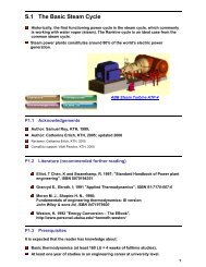
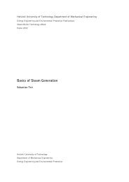
The gas <strong>turbine</strong> in the T-S Diagram<br />
T<br />
Tflame<br />
t5<br />
p5, t5m<br />
Combustor cooling<br />
Turbine cooling<br />
η ct = (t5m - t6)/(t5m - t6s)<br />
©Siemens Power Generation 2003. All Rights Reserved<br />
p3, t3<br />
η c = (t3s - t2)/(t3 - t2)<br />
p6, t6<br />
p7, t7<br />
η pt = (t6m - t7)/(t6m - t7s)<br />
p2, t2<br />
s<br />
25/04/2006<br />
Power Generation 10
25/04/2006<br />
Power Generation 11<br />
SGT-600 Combustor and<br />
secondary flows<br />
©Siemens Power Generation 2003. All Rights Reserved
.<br />
SGT- 600 DLE<br />
combustor<br />
©Siemens Power Generation 2003. All Rights Reserved<br />
25/04/2006<br />
DLE combustor for 25 ppmv<br />
with EV burners since 1991<br />
Power Generation 12
Dual Fuel EV-Burner<br />
©Siemens Power Generation 2003. All Rights Reserved<br />
Combustion<br />
air<br />
<strong>Gas</strong><br />
Oil +<br />
Water<br />
<strong>Gas</strong><br />
Spray<br />
evaporation<br />
Vortex<br />
breakdown<br />
Features<br />
Features<br />
Mixing Mixing of of the the gas gas and and air air is<br />
is<br />
achieved shortly shortly after after the the gas<br />
gas<br />
injection holes<br />
holes<br />
Vortex Vortex breakdown stabilizes the<br />
the<br />
flame flame in in free free space<br />
space<br />
No No mechanical flame flame holder holder is<br />
is<br />
necessary<br />
Benefits<br />
Benefits<br />
Homogenous mixture mixture leads leads to<br />
to<br />
very very low low emission levels<br />
levels<br />
Design Design is is simple simple and and reliable<br />
reliable<br />
Atomization<br />
<strong>Gas</strong> injection<br />
holes<br />
Ignition<br />
Flame<br />
front<br />
25/04/2006<br />
Power Generation 13
AEV dual fuel burner, more details<br />
Main gas<br />
Pilot oil<br />
©Siemens Power Generation 2003. All Rights Reserved<br />
Main oil<br />
Pilot gas<br />
Concentric tubes for fuel supply<br />
25/04/2006<br />
- AEV Burner -<br />
Power Generation 14
Engine package<br />
©Siemens Power Generation 2003. All Rights Reserved<br />
• All gas <strong>turbine</strong>s are delivered as a package that includes<br />
• a base skid on which the core engine and gear box are mounted<br />
• on or in the skid are the systems mounted<br />
•lubrication oil tank, pumps and valves<br />
•fuel oil pumps and gas valves<br />
•measuring equipment<br />
•sound cover etc<br />
• With the <strong>turbine</strong> is delivered the <strong>control</strong> equipment for<br />
• gas <strong>turbine</strong> <strong>control</strong><br />
• generator <strong>control</strong><br />
• electric power <strong>control</strong> if applicable<br />
• the local <strong>control</strong> panel<br />
25/04/2006<br />
Power Generation 15
SGT-800, 3-D view<br />
Simple cycle<br />
Exhaust with silencer<br />
Air intake filter<br />
Electrical and<br />
Control module<br />
Ventilation Inlet<br />
©Siemens Power Generation 2003. All Rights Reserved<br />
Fire extinguishing<br />
Ventilation Outlet<br />
Signal handling<br />
module<br />
Generator<br />
<strong>Gas</strong> fuel unit 2<br />
<strong>Gas</strong> fuel unit 1<br />
Generator air intake<br />
Propane tank<br />
(start liquid fuel)<br />
Generator air outlet<br />
25/04/2006<br />
Lube oil sys.<br />
Lube oil cooler<br />
Power Generation 16
25/04/2006<br />
Power Generation 17<br />
Auxiliary systems<br />
©Siemens Power Generation 2003. All Rights Reserved
<strong>Gas</strong> fuel system SGT-600<br />
<strong>Gas</strong> fuel unit 2, located inside the GT enclosure<br />
©Siemens Power Generation 2003. All Rights Reserved<br />
Enclosure wall<br />
Quick shut-off valves<br />
<strong>Gas</strong> <strong>control</strong> valves<br />
From gas fuel unit 1<br />
To atmosphere<br />
Ventilation valves<br />
25/04/2006<br />
Power Generation 18
25/04/2006<br />
SGT-600, Instrumentation<br />
Probe location<br />
Power Generation 19<br />
©Siemens Power Generation 2003. All Rights Reserved
Control system standard Configuration<br />
SGT-800 Power Generation (Simple Cycle)<br />
Hardcopy<br />
Event & alarm<br />
printer (option)<br />
TCP/IP<br />
Operate IT<br />
Process Portal<br />
Pocket Computer,<br />
SMS alarming,<br />
e-mail (Options)<br />
Dual Masterbus 300<br />
©Siemens Power Generation 2003. All Rights Reserved<br />
•Enhanced instrumentation reliability, " 2<br />
out of 3" on instruments tripping during<br />
operation,<br />
Synchron.<br />
equipment<br />
Generator<br />
protection<br />
Generator Control panel<br />
• Sequencing • Dual CPUs<br />
• Open loop<br />
Optional Modbus or Ethernet OPC<br />
AVR<br />
GT <strong>control</strong> panel (On <strong>turbine</strong> skid)<br />
Dual Fieldbus AF100<br />
• Governor<br />
• Safety Ch. 1<br />
• Dual CPUs<br />
AC-servo<br />
drive<br />
• Safety<br />
Ch. 2<br />
• I/O<br />
Vibration<br />
Monitor<br />
+/- 0<br />
Fire<br />
exting<br />
Lube<br />
oil<br />
VFD<br />
Start<br />
VFD<br />
MCC<br />
GCB<br />
+1400<br />
+1400<br />
+1050<br />
+1400<br />
+1050<br />
+/- 0<br />
25/04/2006<br />
OPTIONS IN RED<br />
Power Generation 20
Control system standard Configuration<br />
SGT-800 Mechanical Drive (Simple Cycle)<br />
Hardcopy<br />
Event & alarm<br />
printer (option)<br />
TCP/IP<br />
Masterbus 300<br />
Operate IT<br />
Process Portal<br />
Compressor Control panel<br />
Pocket Computer,<br />
SMS alarming,<br />
e-mail (Options)<br />
GT <strong>control</strong> panel (On <strong>turbine</strong> skid in EEx(p) module)<br />
©Siemens Power Generation 2003. All Rights Reserved<br />
• Sequencing<br />
• Open loop<br />
Optional Modbus<br />
Antisurge<br />
(Option)<br />
Fieldbus AF100<br />
• Governor<br />
• Safety Ch. 1<br />
AC-servo<br />
drive<br />
• Safety<br />
Ch. 2<br />
• I/O<br />
Vibration<br />
Monitor<br />
+/- 0<br />
Fire<br />
exting<br />
Lube<br />
oil<br />
VFD<br />
Start<br />
VFD<br />
MCC<br />
Compressor<br />
+1400<br />
+1400<br />
+1050<br />
+1400<br />
+1050<br />
+/- 0<br />
25/04/2006<br />
Power Generation 21
Introduction to <strong>control</strong> logic<br />
©Siemens Power Generation 2003. All Rights Reserved<br />
• The gas <strong>turbine</strong> is <strong>control</strong>led in different ways depending on application<br />
but<br />
• in simple cycle arrangement for power generation there are two<br />
modes<br />
•constant power at a given electric frequency<br />
•full power<br />
• in cogeneration coupled to a process industry the steam demand<br />
from the waste heat recovery boiler is governing the gas <strong>turbine</strong><br />
heat input<br />
• in combined cycle operation the total power or heat demand is<br />
governing the gas <strong>turbine</strong> heat input<br />
25/04/2006<br />
Power Generation 22
Turbine governor<br />
Block diagram<br />
©Siemens Power Generation 2003. All Rights Reserved<br />
NGG<br />
T0<br />
X<br />
NPT<br />
PEL<br />
NGG<br />
T7<br />
NGG<br />
STC<br />
f(x,y)<br />
MPC<br />
PI PI<br />
FLC<br />
PI PI<br />
GAC<br />
f(x)<br />
T7L<br />
PI PI<br />
NGGL<br />
PI PI<br />
NGG<br />
T0<br />
<<br />
GDC<br />
f(x,y)<br />
><br />
FUEL<br />
DISTR<br />
G<br />
L<br />
SPLIT<br />
1<br />
2<br />
T3<br />
f(x)<br />
NGG<br />
TFLAME<br />
f(x)<br />
f(x)<br />
SFC<br />
IGCV<br />
f(x)<br />
CBC<br />
f(x)<br />
PGCV<br />
MGCV<br />
M~ LFP<br />
IGV<br />
CBPV<br />
PEL<br />
LLD<br />
D<br />
NGG<br />
BVC<br />
f(x)<br />
BV2<br />
25/04/2006<br />
Power Generation 23
Basic <strong>control</strong><br />
©Siemens Power Generation 2003. All Rights Reserved<br />
• Generally the basic <strong>control</strong> is simple<br />
• more fuel gives more power, but in the gas <strong>turbine</strong> the air flow has<br />
to be matched to the fuel flow in order to provide<br />
•long life of hot parts<br />
•low emissions<br />
• for the twin shaft unit the air flow increases with load, since the gas<br />
generator rotor accelerates<br />
• for the single shaft unit the air flow in increased by opening of the<br />
inlet guide vanes of the compressor in a <strong>control</strong>led way<br />
25/04/2006<br />
Power Generation 24
Full and Peak Power<br />
©Siemens Power Generation 2003. All Rights Reserved<br />
• In order to provide long life of the gas <strong>turbine</strong> parts there are limitations<br />
for the operation on<br />
• <strong>turbine</strong> inlet temperature, to protect the <strong>turbine</strong> front end<br />
• <strong>turbine</strong> exit temperature, to protect the exit end of the <strong>turbine</strong> and<br />
the exhaust casing and waste heat recovery boiler<br />
• rotor speed to protect compressor and <strong>turbine</strong> discs from rupture<br />
• power to protect the shafts, gear box and generator<br />
• Full power is reached when the lowest of these limits is reached. The<br />
limits are somewhat dependent on ambient conditions and fuel type.<br />
• The temperature limits can be overruled by the customer in order to<br />
make some 10% more power, peak power, but at shorter lifetime of the<br />
engine hot section<br />
25/04/2006<br />
Power Generation 25
Turbine inlet temperature limit<br />
• Most often the limitation is the maximum <strong>turbine</strong> gas inlet temperature,<br />
TIT, which can be one of<br />
• combustor exit temperature<br />
• rotor inlet temperature<br />
• <strong>turbine</strong> mixed inlet temperature<br />
©Siemens Power Generation 2003. All Rights Reserved<br />
• TIT is a characteristic temperature that is related to a certain life time of<br />
the hot parts in the <strong>turbine</strong><br />
• For an industrial <strong>turbine</strong> the design life time of the hot parts is usually<br />
around 40000 equivalent hours<br />
• the customer can choose to operate at a shorter hot section life at times<br />
when electric price is high, peak power or flat rating<br />
25/04/2006<br />
Power Generation 26
Equivalent hours<br />
• The life time of a component is usually determined by<br />
• high temperature creep due to high stress and high temperature or<br />
• low cycle fatigue LCF caused by the start and stop cycles<br />
©Siemens Power Generation 2003. All Rights Reserved<br />
• the life time consumption is most often calculated as Equivalent hours.<br />
Each part has its own Eq.hour formula depending on design and<br />
operation conditions. For the older gas <strong>turbine</strong>s creep was the critical<br />
factor, but in modern gas <strong>turbine</strong>s LCF is dominating<br />
• For simplicity in the <strong>control</strong> system every company has their own<br />
formula for equivalent hours based on the most critical part, which<br />
usually is the first <strong>turbine</strong> blade.<br />
The simple one is a mixture of creep hours and LCF cycles<br />
25/04/2006<br />
Eq.hrs = operating hrs*fuel factor + starts*start factor<br />
cf = 1.0 for natural gas<br />
cf = 1.4 for diesel oil<br />
cstart = 15÷50<br />
Power Generation 27
Turbine inlet temperature calculation<br />
• The <strong>turbine</strong> inlet temperature can not be measured, since it is too hot<br />
and too risky.<br />
• The <strong>control</strong> system language is not apt for complicated computations,<br />
so simplicity is preferred<br />
©Siemens Power Generation 2003. All Rights Reserved<br />
• How is the <strong>turbine</strong> inlet temperature calculated from measured values<br />
• t2, p2<br />
• t3, p3<br />
• t7, p7<br />
t5m = t7/(1-ηt*(1-(p7/p5) (κ-1)/κ ≅ t7 + k1*p5/p7 + k2<br />
t5 = (t5m*cp5m –x* t3*cp3)/(1 - x)*cp5 ≅ (t5m –x*t3)/(1 - x)<br />
x = mcool/m2<br />
25/04/2006<br />
Power Generation 28
The gas <strong>turbine</strong> in the T-S Diagram<br />
T<br />
Tflame<br />
t5<br />
p5, t5m<br />
Combustor cooling<br />
Turbine cooling<br />
η ct = (t5m - t6)/(t5m - t6s)<br />
©Siemens Power Generation 2003. All Rights Reserved<br />
p3, t3<br />
η c = (t3s - t2)/(t3 - t2)<br />
p6, t6<br />
p7, t7<br />
η pt = (t6m - t7)/(t6m - t7s)<br />
p2, t2<br />
s<br />
25/04/2006<br />
Power Generation 29
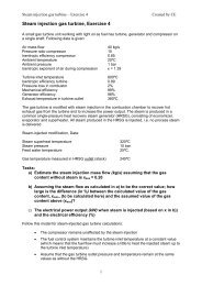
T5/T7 factor vs pressure ratio<br />
2.000<br />
1.800<br />
1.600<br />
©Siemens Power Generation 2003. All Rights Reserved<br />
T5/T7 factor<br />
1.400<br />
1.200<br />
1.000<br />
0.800<br />
0.600<br />
0.400<br />
0.200<br />
Calculation<br />
Approximation<br />
0.000<br />
0 10 20 30<br />
Turbine Pressure Ratio<br />
25/04/2006<br />
Power Generation 30
The gas <strong>turbine</strong> in the T-S Diagram<br />
T<br />
Tflame<br />
t5<br />
p5, t5m<br />
Combustor cooling<br />
Turbine cooling<br />
η ct = (t5m - t6)/(t5m - t6s)<br />
©Siemens Power Generation 2003. All Rights Reserved<br />
p3, t3<br />
η c = (t3s - t2)/(t3 - t2)<br />
p6, t6<br />
p7, t7<br />
η pt = (t6m - t7)/(t6m - t7s)<br />
p2, t2<br />
s<br />
25/04/2006<br />
Power Generation 31
T7 limit<br />
Finally the formula can be reduced to<br />
t5 = (t7 + k1*p5/p7 + k2 – k3*x*t3)/(1-x)<br />
©Siemens Power Generation 2003. All Rights Reserved<br />
• For simplicity the <strong>control</strong> system computes the maximum allowed t7 for the<br />
maximum t5<br />
• t7limit = t5limit*(1-x) – k1*p3/p7 - k2 + k3*x*t3<br />
• the constants in the equation is derived from performance program<br />
calculations and adjusted after performance tests<br />
• the average temperatures t3 and t7 is measured by a few operating probes,<br />
which are not measuring the true averages. During the performance tests a<br />
number of special probes are used to get the true averages. The operating<br />
values are then corrected for the differences found at the performance test.<br />
25/04/2006<br />
Power Generation 32
Blade temperatures and life<br />
• Generally the material temperature of a gas <strong>turbine</strong> blade should be lower<br />
than 850˚C, but with oxidation protective coatings and thermal boundary<br />
coatings (ceramic layers) temperatures at around 950˚C is used, but often<br />
with reduced life time as the result.<br />
©Siemens Power Generation 2003. All Rights Reserved<br />
• the internally cooled blade has a metal temperature in between the gas<br />
temperature and the cooling air temperature. The cooling factor for the blade<br />
is determined in tests<br />
ε =(tm – tcool)/(tgas – tcool<br />
and the material temperature can be estimated during operation<br />
tm = tcool + ε*(tgas – tcool)<br />
• With stress levels that comes from FEM calculations, the material<br />
temperature and the material data, the blade life consumption can be<br />
computed<br />
25/04/2006<br />
Power Generation 33
SGT-600 Turbines<br />
©Siemens Power Generation 2003. All Rights Reserved<br />
<strong>Gas</strong> temp 1215C<br />
Internally cooled<br />
blades for a<br />
material temp of<br />
850C<br />
<strong>Gas</strong> temp 545C<br />
Uncooled<br />
blades<br />
<strong>Gas</strong> temp 800C<br />
25/04/2006<br />
Power Generation 34
Turbine exit T7limit<br />
• The t7limit calculated from the t5limit is usually the critical one, but at high<br />
ambient temperatures the t7limit based on the maximum <strong>turbine</strong> exit<br />
temperature could be lower.<br />
• This is usually a fixed temperature based on the material quality of the<br />
exhaust casing<br />
©Siemens Power Generation 2003. All Rights Reserved<br />
• The <strong>control</strong> system chooses the lowest of the two t7limits<br />
25/04/2006<br />
Power Generation 35
Maximum speed<br />
©Siemens Power Generation 2003. All Rights Reserved<br />
• On a twin shaft unit the gas generator rotor is running free. The speed is<br />
determined by the thermodynamic balance between compressor and <strong>turbine</strong>.<br />
• usually the gas generator rotor speed is going down in speed with<br />
increasing ambient temperature, but at very low ambient temperatures<br />
the speed may become too high, creating excessive stresses in the rims<br />
of the discs where the blades are attached<br />
• on units always operating in hot climate, the split of power between<br />
compressor <strong>turbine</strong> and power <strong>turbine</strong> is changed to increase the speed<br />
(and air flow) of the gas generator rotor.<br />
• How?<br />
25/04/2006<br />
Power Generation 36
Maximum power<br />
• Due to the higher density of the air at low ambient temperature, the air mass<br />
flow is increased. More fuel can be added and the power goes up.<br />
• The generator capacity is usually the limit for power output, but there may be<br />
some limitation in shafts, gear teeth and couplings.<br />
©Siemens Power Generation 2003. All Rights Reserved<br />
• Most of these parts are however designed for electrical shortening torque<br />
25/04/2006<br />
Power Generation 37
Power Limitations from ambient<br />
temperature<br />
Max generator power<br />
Max compressor speed<br />
Max <strong>turbine</strong> inlet temperature at 40000 hrs life<br />
Flat rating<br />
©Siemens Power Generation 2003. All Rights Reserved<br />
Power output MW<br />
Nominal Power<br />
Peak Power<br />
-45 -30 -15 0 15 30 45<br />
Ambient temperature °C<br />
25/04/2006<br />
Power Generation 38
IGV and bleed valves<br />
120<br />
100<br />
IGV&Bleed Valve positions (%)<br />
BV2 position (%)<br />
IG V p o sitio n (% )<br />
BV1 position (%)<br />
Actual IGV<br />
Actual BV2<br />
Actual BV1<br />
©Siemens Power Generation 2003. All Rights Reserved<br />
Valve position %<br />
80<br />
60<br />
40<br />
20<br />
0<br />
2000 4000 6000 8000 10000 12000<br />
Nnorm rpm<br />
25/04/2006<br />
Power Generation 39
Combustion <strong>control</strong><br />
©Siemens Power Generation 2003. All Rights Reserved<br />
NOx ppm<br />
50<br />
40<br />
CO<br />
30<br />
20<br />
10<br />
Basic strategy to keep<br />
within window in as<br />
wide operating range<br />
as possible<br />
NOx<br />
AEV Burner<br />
AEV Burner<br />
DLE <strong>Gas</strong> & Oil<br />
CO ppm<br />
40<br />
30<br />
20<br />
10<br />
1600 1700 1800 1900<br />
Flame Temp K<br />
- Combustor <strong>control</strong> strategy -<br />
Power Generation 40
Combustion system <strong>control</strong> and<br />
supervision<br />
• The basic <strong>control</strong> is to govern the gas valves or oil pumps for correct<br />
flow, but…<br />
• a low emission system has a limited operating window, in which it<br />
is can be quite complicated to stay<br />
• many tricks are used to achieve acceptable part load performance<br />
©Siemens Power Generation 2003. All Rights Reserved<br />
• Very often a pilot flame is used to stabilise the main flame when the<br />
flame temperature is getting too low (moving the CO line to the left), but<br />
with a NOx penalty<br />
• Fuel staging is one common practise, thus concentrating the fuel to<br />
fewer burners with higher flame temperature as a result. Uneven <strong>turbine</strong><br />
temperatures can be harmful to <strong>turbine</strong> life<br />
• Reduction of burner air flow by<br />
• combustor bypass which reduces the flow to the burner but not to<br />
the <strong>turbine</strong><br />
• compressor bleed, that reduces the flow to both burner and <strong>turbine</strong><br />
25/04/2006<br />
Power Generation 41
SGT-700 combustion <strong>control</strong><br />
Low NOx >50% load<br />
Main fuel Pilot fuel<br />
VGV<br />
Bypass<br />
©Siemens Power Generation 2003. All Rights Reserved<br />
NOx ~ 10 ppmv on gas<br />
25/04/2006<br />
NOx ~ 20 ppmv on diesel oil<br />
Power Generation 42
Combustion Control Strategies<br />
• The <strong>control</strong> strategies varies with the machine type and burner design<br />
• in GT10B there is a pilot and a combustor bypass system<br />
• in GTX100 the air flow can be <strong>control</strong>led by the compressor inlet guide<br />
vanes, but there is also a pilot<br />
©Siemens Power Generation 2003. All Rights Reserved<br />
• Since the emissions are very much dependent on the flame temperature, it is<br />
used as the <strong>control</strong>ling parameter.<br />
• The flame temperature is a function of<br />
• the normalised Air/Fuel ratio λ = mair/mfuel/(mair/mfuel) St<br />
• the air temperature<br />
• The flame temperature is basically calculated as t5 above, but there are other<br />
methods, more or less successful<br />
• λ can be calculated from the Oxygen left in the exhaust air<br />
• λ can be calculated from measured fuel and air flows<br />
25/04/2006<br />
Power Generation 43
Combustion Control Strategies<br />
• The pilot/total fuel flow ratio and the bypass are flow rate are then governed<br />
by the flame temperature<br />
• Usually the <strong>turbine</strong> is started on 100% pilot, which is then reduced with<br />
increasing power to a few % at full load, but not fully closed. At a fast load<br />
reduction the pilot has to be quick to avoid flame out.<br />
©Siemens Power Generation 2003. All Rights Reserved<br />
• the pfr schedule is determined at tests and is dependent on combustion<br />
stability for the lower limit and emissions for the higher limit. The pilot is<br />
usually a diffusion flame that produces a lot of NOx.<br />
• Many units does not have a bypass system, but bleeds off air from the<br />
compressor. The combustion effect with higher flame temperature can be<br />
achieved, but at a loss of part load efficiency. The limit for the bleed is very<br />
often the <strong>turbine</strong> exit temperature.<br />
25/04/2006<br />
Power Generation 44
Performance with bleed/bypass<br />
options<br />
GT10B Performance with bypass alternatives<br />
0.5<br />
1600<br />
©Siemens Power Generation 2003. All Rights Reserved<br />
Efficiency<br />
0.4<br />
0.3<br />
0.2<br />
Tflame with bypass or bleed<br />
Efficiency<br />
Tflame without<br />
b<br />
w/wo Bypass<br />
anti-icing<br />
bleed 3<br />
1400<br />
1200<br />
1000<br />
800<br />
600<br />
Tflame, deg C<br />
0.1<br />
T7<br />
400<br />
80% load<br />
200<br />
0<br />
0 5000 10000 15000 20000 25000<br />
0<br />
25/04/2006<br />
Power kW<br />
Power Generation 45
Burner supervision<br />
• The combustion is checked by<br />
• flame detectors<br />
• exhaust temperatures<br />
• pulsation measurements<br />
©Siemens Power Generation 2003. All Rights Reserved<br />
• if the flame detectors does not see a flame, the fuel is directly shut off to<br />
prevent an explosion, since re-ignition can happen<br />
• the t7 probes in the <strong>turbine</strong> diffuser can detect burners that are not working<br />
well by showing<br />
• too low temperature, indicating some blockage of fuel injectors<br />
• too high temperature, which cold be the result of fuel leakage or some<br />
disturbance on the air side<br />
• the <strong>control</strong> system checks the deviations and gives alarm and reduces<br />
load if certain limits are reached<br />
25/04/2006<br />
Power Generation 46
Sequencing<br />
©Siemens Power Generation 2003. All Rights Reserved<br />
• The start up of a gas <strong>turbine</strong> is fully automatic, but ….<br />
• there are a lot of sequences to perform in a short time, starting and<br />
checking<br />
•lube oil system<br />
•ventilation of gas generator room to prevent explosion from fuel fumes<br />
•ventilation to <strong>turbine</strong> and exhaust duct by running the gas generator at<br />
ventilation speed to prevent explosion of remaining fuel<br />
•fuel system for leaks<br />
•measurement systems etc<br />
•compressor inlet guide vanes and bleeds<br />
• Finally the gas generator is brought up to ignition speed. After<br />
cross ignition the rotor is accelerated along ramps up to idle speed.<br />
• During the acceleration the compressor bleed valves are closing.<br />
• At idle the electrical breakers are closed at phasing speed and the<br />
loading starts<br />
25/04/2006<br />
Power Generation 47
Mech drive start<br />
Turbine exhaust temp<br />
GG speed<br />
©Siemens Power Generation 2003. All Rights Reserved<br />
Prim fuel flow<br />
PT speed<br />
Compressor exhaust pressure<br />
IGV<br />
25/04/2006<br />
Power Generation 48
Transients<br />
©Siemens Power Generation 2003. All Rights Reserved<br />
• Fuel change over<br />
• automatic fuel change over is possible on dual fuel units<br />
• the change over from gas to oil if gas pressure gets too low is done in 10<br />
to 30 seconds, depending on requirement<br />
• the transient operation requires a speed up of the <strong>control</strong> amplification<br />
and quite a lot of fine tuning<br />
• the fuel change over from oil to gas is usually initiated manually when the gas<br />
system is back in operation<br />
• Surge protection<br />
• if for some reason the compressor runs into the surge line, the unit will<br />
trip after the first surge cycle<br />
25/04/2006<br />
Power Generation 49
Performance supervision<br />
• During operation the performance deteriorates mainly due to fouling of the<br />
compressor. Dust from the air attaches to the blade surfaces and increases<br />
the flow losses.<br />
• Deterioration also comes from the wear of seals increasing leakages.<br />
©Siemens Power Generation 2003. All Rights Reserved<br />
• The <strong>control</strong> system checks the loss in performance and indicates when it is<br />
time to do a compressor wash<br />
• on line or off line<br />
• Most of the performance is regained at a off line wash, while the on line wash<br />
has less good effect but is used when it is not possible to stop<br />
• The deterioration due to wear is only reduced at overhauls, when blades and<br />
seals are exchanged<br />
25/04/2006<br />
Power Generation 50
Deterioration of P e and S.H.C<br />
up to 120 000 eq. hrs, nominal<br />
• Deterioration is shown in comparison with “new and clean”<br />
engine. No guarantee beyond original warranty period.<br />
Natural gas fuel<br />
Average 1.4% H.R & 2.4%<br />
power<br />
Liquid fuel<br />
Average 1.8% H.R & 3.1% power<br />
©Siemens Power Generation 2003. All Rights Reserved<br />
Deterioration<br />
103%<br />
102%<br />
101%<br />
100%<br />
99%<br />
98%<br />
Expected GT10B deterioration expanded to 120000 h - <strong>Gas</strong>eous fuel<br />
Heat Rate<br />
Power Output<br />
Deterioration<br />
103%<br />
102%<br />
101%<br />
100%<br />
99%<br />
98%<br />
Expected GT10B deterioration expanded to 120000 h - Liquid fuel<br />
Heat Rate<br />
Power Output<br />
97%<br />
97%<br />
96%<br />
96%<br />
95%<br />
95%<br />
94%<br />
0 20000 40000 60000 80000 100000 120000<br />
Equivalent Operating Hours<br />
94%<br />
0 20000 40000 60000 80000 100000 120000<br />
Equivalent Operating Hours<br />
25/04/2006<br />
Power Generation 51
Compressor washing system, SDB<br />
Standard P&ID GT10B2: 992891<br />
Plenum<br />
Four washing nozzles<br />
Washing unit<br />
©Siemens Power Generation 2003. All Rights Reserved<br />
Instrument air<br />
supply<br />
Reciprocating pump<br />
Filling of fluid<br />
Filling of fluid<br />
Drain delivery limits<br />
Rinsing detergent 80 liters (water+washing fluid<br />
Watertank 80liters<br />
25/04/2006<br />
Power Generation 52
Remote supervision<br />
©Siemens Power Generation 2003. All Rights Reserved<br />
• The <strong>control</strong> system can be accessed<br />
• at the local <strong>control</strong> room close to the <strong>turbine</strong>, which is used only by the<br />
service crews<br />
• the plant <strong>control</strong> room, in which the gas <strong>turbine</strong> <strong>control</strong> is a PC<br />
• at the gas <strong>turbine</strong> suppliers remote operation station<br />
• Alarm signals can be sent to operators mobile phone<br />
25/04/2006<br />
Power Generation 53
SGT-600 Control system<br />
configuration<br />
©Siemens Power Generation 2003. All Rights Reserved<br />
Operator's station<br />
PC available<br />
as an option<br />
• HP B2000<br />
workstations<br />
• Very high computing<br />
performance<br />
• High resolution<br />
graphical user interface<br />
• Real-Time<br />
Accelerator<br />
• System software<br />
• UNIX, OSF/Motif, SQL,<br />
X Windows System,<br />
TCP/IP<br />
25/04/2006<br />
Power Generation 54
25/04/2006<br />
Power Generation 55<br />
SGT-600 Operator displays<br />
Unit start/stop<br />
©Siemens Power Generation 2003. All Rights Reserved
25/04/2006<br />
Power Generation 56<br />
SGT-600 Operator displays<br />
Unit operation<br />
©Siemens Power Generation 2003. All Rights Reserved
25/04/2006<br />
Power Generation 57<br />
SGT-600 Operator displays<br />
Log page<br />
©Siemens Power Generation 2003. All Rights Reserved
25/04/2006<br />
Power Generation 58<br />
SGT-600 Operator displays<br />
Fuel page<br />
©Siemens Power Generation 2003. All Rights Reserved
25/04/2006<br />
Power Generation 59<br />
SGT-600 Operator displays<br />
Lubrication oil<br />
©Siemens Power Generation 2003. All Rights Reserved
25/04/2006<br />
Power Generation 60<br />
Operator displays<br />
Typical Alarm and event list<br />
©Siemens Power Generation 2003. All Rights Reserved
Turbine <strong>control</strong> system features<br />
Valuable features<br />
©Siemens Power Generation 2003. All Rights Reserved<br />
M<br />
• Excellent operator's interface with colour graphics<br />
• One display for every sub system<br />
• Trend monitoring<br />
• Self supervisory<br />
• System status displays<br />
• Object displays for every signal in the system<br />
• Alarm and event recording<br />
• Hardcopy printer<br />
• Function block programming with excellent printouts<br />
• Programming of main <strong>control</strong>ler from operator's<br />
screen<br />
• Online programmable<br />
• Open to external systems<br />
• Good track record of retrofit - protects investment<br />
• Minimized on site cabling (safe area installation)<br />
25/04/2006<br />
Power Generation 61
Control system options<br />
Option<br />
Option<br />
1 or more X-terminal<br />
remote OS<br />
Advant Station 520 OS<br />
Option<br />
Option<br />
1 or 2 Advant Station 520 OS<br />
Alarm & Event<br />
Matrix Printer<br />
©Siemens Power Generation 2003. All Rights Reserved<br />
MB300<br />
Option<br />
Option<br />
Advant Fieldbus 100<br />
Advant AC400<br />
• Automation & Sequencing<br />
• Open loop <strong>control</strong>s<br />
• Local I/O<br />
Option<br />
Option<br />
Hardcopy Printer<br />
Modbus<br />
Hardwired<br />
Opto modem and cable<br />
Option<br />
Option<br />
Option<br />
Option<br />
Option<br />
Option<br />
AC 100<br />
AC 100<br />
AC 100<br />
AC 110<br />
• Safety System ch 1<br />
• Remote I/O<br />
• Safety System ch 2<br />
• Turbine <strong>control</strong>ler<br />
Option<br />
Option<br />
•Surge <strong>control</strong>ler<br />
• Voltage <strong>control</strong>ler<br />
(power gen only)<br />
25/04/2006<br />
GT skid mounted equipment<br />
Power Generation 62
Control system simulations<br />
• The logics are basically figured out of us, the engine designers, but the logics<br />
is programmed by others<br />
• There will be errors both in the logics and the programming<br />
• Simulations to check it can be done in simple or sophisticated ways<br />
©Siemens Power Generation 2003. All Rights Reserved<br />
• In the simple way an Excel program can be used<br />
• The gas <strong>turbine</strong> performance is calculated at small time steps<br />
•0.5 sec at fast transients (valve openings)<br />
•1 sec at normal start sequences (acceleration and trip)<br />
•10 sec at normal loading<br />
• Usually the rotor mass can be neglected (not at load rejection)<br />
25/04/2006<br />
Power Generation 63
SGT-600 Compressor<br />
• The compressor has<br />
• variable guide vanes before stage 1&2<br />
• bleed at stage 2 and 5<br />
p3/p2<br />
15<br />
©Siemens Power Generation 2003. All Rights Reserved<br />
10<br />
5<br />
The operating line is determined by<br />
- the compressor <strong>turbine</strong> flow areas<br />
- <strong>turbine</strong> IGV+ cooling ducts<br />
- bleed valves<br />
1<br />
Normalised inlet mass flow m n = m*p 2 /p n *rot(T n /T 2 )<br />
25/04/2006<br />
Power Generation 64
The compressor stage flow<br />
.<br />
The compressor blade path is like diffusers<br />
∆h/u 2<br />
η<br />
©Siemens Power Generation 2003. All Rights Reserved<br />
Surge<br />
In retarding flows the<br />
boundary layers grow<br />
and tend to separate.<br />
Low stage load = many<br />
stages<br />
25/04/2006<br />
cax/u<br />
Power Generation 65
Surge protection<br />
GT10B Surge protection<br />
18<br />
16<br />
14<br />
©Siemens Power Generation 2003. All Rights Reserved<br />
Pressure ratio<br />
12<br />
10<br />
8<br />
6<br />
4<br />
p3/p2<br />
operating line<br />
p3/p3 surge line<br />
2<br />
0<br />
5000 6000 7000 8000 9000 10000 11000 12000 13000<br />
Norm speed rpm<br />
25/04/2006<br />
Power Generation 66