Prestige Trimax control supplement - Coastal Winair
Prestige Trimax control supplement - Coastal Winair
Prestige Trimax control supplement - Coastal Winair

You also want an ePaper? Increase the reach of your titles
YUMPU automatically turns print PDFs into web optimized ePapers that Google loves.
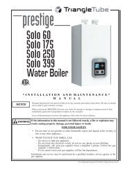
prestige<br />
Solo 60<br />
Solo 175<br />
Solo 250<br />
Solo 399<br />
Water Boiler<br />
L<br />
I S T E D<br />
* I N S T A L L A T I O N A N D M A I N T E N A N C E *<br />
M A N U A L<br />
NOTICE<br />
Warranty Registration Card must be filled out by the customer and mailed within thirty (30) days of installation<br />
in order to gain warranty coverage.<br />
When receiving the PRESTIGE Solo unit, any claims for damage or shortage in shipment must be filed<br />
immediately against the transportation company by the consignee.<br />
Leave all documentation received with appliance with owner for future reference.<br />
WARNING<br />
If the information in this manual is not followed exactly, a fire or explosion may<br />
result causing property damage, personal injury or death.<br />
FOR YOUR SAFETY<br />
• Do not store or use gasoline or other flammable vapors and liquids in the vicinity of<br />
this or any other appliance.<br />
• WHAT TO DO IF YOU SMELL GAS<br />
- Do not try to light any appliance<br />
- Do not touch any electrical switch; do not use any phone in your building.<br />
- Immediately call your gas supplier from a neighbor’s phone. Follow the gas<br />
supplier’s instructions.<br />
- If you cannot reach your gas supplier, call the fire department.<br />
Installation and service must be performed by a qualified installer, service agency or the<br />
gas supplier.<br />
2011-50 Manual <strong>Prestige</strong> 60/175/250/399_TriMax_Revised 11/11/11
Table of Contents<br />
PRODUCT AND SAFETY INFORMATION<br />
Definitions. . . . . . . . . . . . . . . . . . . . . . . . . . . . . . . . . . . . . . . . . . . . . . . . . . . 1<br />
Product and Safety Information . . . . . . . . . . . . . . . . . . . . . . . . . . . . . . . . . . 2<br />
SECTION I - PRE-INSTALLATION ITEMS<br />
Code Compliance . . . . . . . . . . . . . . . . . . . . . . . . . . . . . . . . . . . . . . . . . . . . . 3<br />
Determining Product Location . . . . . . . . . . . . . . . . . . . . . . . . . . . . . . . . . . . 3<br />
Boiler Replacement. . . . . . . . . . . . . . . . . . . . . . . . . . . . . . . . . . . . . . . . . . . . 3<br />
Recommended Clearances . . . . . . . . . . . . . . . . . . . . . . . . . . . . . . . . . . . . . . 3-4<br />
Residential Garage Installations . . . . . . . . . . . . . . . . . . . . . . . . . . . . . . . . . 4<br />
Boiler Freeze Protection Feature . . . . . . . . . . . . . . . . . . . . . . . . . . . . . . . . . 4<br />
SECTION II - COMBUSTION AIR AND VENTING<br />
Combustion Air Contamination . . . . . . . . . . . . . . . . . . . . . . . . . . . . . . . . . . 5<br />
Ventilation and Combustion Air Requirements - Direct Vent . . . . . . . . . . . 6<br />
Ventilation and Combustion Air Requirements - Category IV . . . . . . . . . . 6<br />
Methods of Accessing Combustion Air into a Space - Category IV . . . . . . 7<br />
- Indoor Combustion Air. . . . . . . . . . . . . . . . . . . . . . . . . . . . . . . . . . 7<br />
- Outdoor Combustion Air . . . . . . . . . . . . . . . . . . . . . . . . . . . . . . . . 7-8<br />
- Combination of Indoor and Outdoor Combustion Air. . . . . . . . . . 9<br />
Combustion Air and Vent Piping . . . . . . . . . . . . . . . . . . . . . . . . . . . . . . . . . 9<br />
Removal of an Existing Boiler from a Common Vent System . . . . . . . . . . 10<br />
Commonwealth of Massachusetts Installation . . . . . . . . . . . . . . . . . . . . . . . 11<br />
SECTION III - UNIT PREPARATIONS<br />
Handling Instructions . . . . . . . . . . . . . . . . . . . . . . . . . . . . . . . . . . . . . . . . . . 12<br />
Wall Mounting Installation . . . . . . . . . . . . . . . . . . . . . . . . . . . . . . . . . . . . . . 12<br />
Wall Mounting Guidelines . . . . . . . . . . . . . . . . . . . . . . . . . . . . . . . . . . . . . . 12<br />
Wall Bracket Installation - Stud Walls . . . . . . . . . . . . . . . . . . . . . . . . . . . . . 13<br />
Wall Bracket Installation - Solid Walls . . . . . . . . . . . . . . . . . . . . . . . . . . . . 13<br />
Boiler Mounting . . . . . . . . . . . . . . . . . . . . . . . . . . . . . . . . . . . . . . . . . . . . . . 13<br />
SECTION IV - BOILER PIPING<br />
General Piping Requirements. . . . . . . . . . . . . . . . . . . . . . . . . . . . . . . . . . . . 14<br />
Pressure Relief Valve . . . . . . . . . . . . . . . . . . . . . . . . . . . . . . . . . . . . . . . . . . 14<br />
Low Water Cut Off Device. . . . . . . . . . . . . . . . . . . . . . . . . . . . . . . . . . . . . . 14<br />
Additional Limit Control . . . . . . . . . . . . . . . . . . . . . . . . . . . . . . . . . . . . . . . 16<br />
Backflow Preventer. . . . . . . . . . . . . . . . . . . . . . . . . . . . . . . . . . . . . . . . . . . . 16<br />
i
Table of Contents<br />
Boiler System Piping Applications. . . . . . . . . . . . . . . . . . . . . . . . . . . . . . . . 16<br />
Expansion Tank and Makeup Water . . . . . . . . . . . . . . . . . . . . . . . . . . . . . . . 16-17<br />
Diaphragm Expansion Tank . . . . . . . . . . . . . . . . . . . . . . . . . . . . . . . 17<br />
Closed-Type Expansion Tank . . . . . . . . . . . . . . . . . . . . . . . . . . . . . . 17<br />
Circulator . . . . . . . . . . . . . . . . . . . . . . . . . . . . . . . . . . . . . . . . . . . . . . . . . . . 17<br />
Sizing Primary Piping. . . . . . . . . . . . . . . . . . . . . . . . . . . . . . . . . . . . . . . . . . 17<br />
Domestic Hot Water System Piping . . . . . . . . . . . . . . . . . . . . . . . . . . . . . . . 17<br />
System Piping - Zone Circulators. . . . . . . . . . . . . . . . . . . . . . . . . . . . . . . . . 17<br />
System Piping - Zone Valves . . . . . . . . . . . . . . . . . . . . . . . . . . . . . . . . . . . . 17<br />
Piping Component Legend . . . . . . . . . . . . . . . . . . . . . . . . . . . . . . . . . . . . . . 18<br />
Near Boiler Piping Diagrams . . . . . . . . . . . . . . . . . . . . . . . . . . . . . . . . . . . . 19<br />
System Piping - Through Boiler. . . . . . . . . . . . . . . . . . . . . . . . . . . . . . . . . . 20<br />
System Piping - Radiant Heating . . . . . . . . . . . . . . . . . . . . . . . . . . . . . . . . . 20<br />
System Piping - Special Applications. . . . . . . . . . . . . . . . . . . . . . . . . . . . . . 20<br />
System Piping - Multiple Units Installation. . . . . . . . . . . . . . . . . . . . . . . . . 20<br />
System Piping Diagrams. . . . . . . . . . . . . . . . . . . . . . . . . . . . . . . . . . . . . . . . 21-23<br />
SECTION V - INSTALLING VENT / COMBUSTION AIR & CONDENSATE DRAIN<br />
Installing Vent and Combustion Air . . . . . . . . . . . . . . . . . . . . . . . . . . . . . . . 24<br />
Installing Condensate Drain Assembly. . . . . . . . . . . . . . . . . . . . . . . . . . . . . 24-25<br />
SECTION VI - GAS PIPING<br />
Gas Supply Piping Connection. . . . . . . . . . . . . . . . . . . . . . . . . . . . . . . . . . . 26<br />
Natural Gas<br />
Pipe Sizing -Natural Gas . . . . . . . . . . . . . . . . . . . . . . . . . . . . . . . . . 27<br />
Natural Gas Supply Pressure Requirements. . . . . . . . . . . . . . . . . . . 27<br />
Propane Gas<br />
Pipe Sizing - Propane Gas . . . . . . . . . . . . . . . . . . . . . . . . . . . . . . . . 28<br />
Propane Gas Supply Pressure Requirements . . . . . . . . . . . . . . . . . . 28<br />
Gas Valve/Venturi Assembly . . . . . . . . . . . . . . . . . . . . . . . . . . . . . . 29<br />
SECTION VII - INTERNAL WIRING<br />
General Requirements. . . . . . . . . . . . . . . . . . . . . . . . . . . . . . . . . . . . . . . . . . 30<br />
Internal Factory Wiring Diagram . . . . . . . . . . . . . . . . . . . . . . . . . . . . . . . . . 31<br />
SECTION VIII - EXTERNAL WIRING<br />
Installation Compliance . . . . . . . . . . . . . . . . . . . . . . . . . . . . . . . . . . . . . . . . 32<br />
Line Voltage Connections. . . . . . . . . . . . . . . . . . . . . . . . . . . . . . . . . . . . . . . 32<br />
Circulator Wiring . . . . . . . . . . . . . . . . . . . . . . . . . . . . . . . . . . . . . . . . . . . . . 32-33<br />
Alarm Wiring . . . . . . . . . . . . . . . . . . . . . . . . . . . . . . . . . . . . . . . . . . . . . . . . 33<br />
ii
Table of Contents<br />
Low Voltage Connections. . . . . . . . . . . . . . . . . . . . . . . . . . . . . . . . . . . . . . . 33<br />
Thermostat Wiring . . . . . . . . . . . . . . . . . . . . . . . . . . . . . . . . . . . . . . . . . . . . 33-34<br />
Outdoor Sensor Wiring. . . . . . . . . . . . . . . . . . . . . . . . . . . . . . . . . . . . . . . . . 34<br />
Domestic Hot Water Wiring . . . . . . . . . . . . . . . . . . . . . . . . . . . . . . . . . . . . . 34<br />
Additional Boiler Limits. . . . . . . . . . . . . . . . . . . . . . . . . . . . . . . . . . . . . . . . 34<br />
External Modulation Control . . . . . . . . . . . . . . . . . . . . . . . . . . . . . . . . . . . . 34<br />
System Sensor Wiring. . . . . . . . . . . . . . . . . . . . . . . . . . . . . . . . . . . . . . . . . . 34-35<br />
Cascade Wiring. . . . . . . . . . . . . . . . . . . . . . . . . . . . . . . . . . . . . . . . . . . . . . . 35<br />
Modbus Wiring . . . . . . . . . . . . . . . . . . . . . . . . . . . . . . . . . . . . . . . . . . . . . . . 35<br />
Zone Valve Wiring . . . . . . . . . . . . . . . . . . . . . . . . . . . . . . . . . . . . . . . . . . . . 36<br />
Zone Circulator Wiring. . . . . . . . . . . . . . . . . . . . . . . . . . . . . . . . . . . . . . . . . 37<br />
System Piping Wiring Diagrams . . . . . . . . . . . . . . . . . . . . . . . . . . . . . . . . . 38-39<br />
SECTION IX - TRIMAX OPERATION<br />
TriMax User Interface . . . . . . . . . . . . . . . . . . . . . . . . . . . . . . . . . . . . . . . . . 40<br />
TriMax Navigation . . . . . . . . . . . . . . . . . . . . . . . . . . . . . . . . . . . . . . . . . . . . 41<br />
<strong>Trimax</strong> Menu Structure. . . . . . . . . . . . . . . . . . . . . . . . . . . . . . . . . . . . . . . . . 42<br />
Home Screen. . . . . . . . . . . . . . . . . . . . . . . . . . . . . . . . . . . . . . . . . . . . . . . . . 43<br />
Status Line Messages . . . . . . . . . . . . . . . . . . . . . . . . . . . . . . . . . . . . . . . . . . 44<br />
Main Menu . . . . . . . . . . . . . . . . . . . . . . . . . . . . . . . . . . . . . . . . . . . . . . . . . . 45<br />
EZ Setup Menu. . . . . . . . . . . . . . . . . . . . . . . . . . . . . . . . . . . . . . . . . . . . . . . 46<br />
Heating EZ Setup . . . . . . . . . . . . . . . . . . . . . . . . . . . . . . . . . . . . . . . . . . . . . 46-47<br />
Domestic Hot Water EZ Setup . . . . . . . . . . . . . . . . . . . . . . . . . . . . . . . . . . . 48-49<br />
EZ Setup Reset . . . . . . . . . . . . . . . . . . . . . . . . . . . . . . . . . . . . . . . . . . . . . . . 49<br />
Display EZ Setup . . . . . . . . . . . . . . . . . . . . . . . . . . . . . . . . . . . . . . . . . . . . . 49<br />
CH/DHW Operation . . . . . . . . . . . . . . . . . . . . . . . . . . . . . . . . . . . . . . . . . . 50<br />
Boiler Information . . . . . . . . . . . . . . . . . . . . . . . . . . . . . . . . . . . . . . . . . . . . 50<br />
Information Items . . . . . . . . . . . . . . . . . . . . . . . . . . . . . . . . . . . . . . . . . . . . . 51<br />
Lockout History . . . . . . . . . . . . . . . . . . . . . . . . . . . . . . . . . . . . . . . . . . . . . . 52<br />
Lockout Screen . . . . . . . . . . . . . . . . . . . . . . . . . . . . . . . . . . . . . . . . . . . . . . . 53<br />
Manual Reset Hard Lockouts . . . . . . . . . . . . . . . . . . . . . . . . . . . . . . . . . . . . 54<br />
Automatic Reset Soft Lockouts . . . . . . . . . . . . . . . . . . . . . . . . . . . . . . . . . . 55<br />
SECTION X - START-UP PREPARATION<br />
Check Boiler System Water Chemistry<br />
Water pH Level 6.0 to 8.0 . . . . . . . . . . . . . . . . . . . . . . . . . . . . . . . . 56<br />
Water Hardness Less Than 7 Grains. . . . . . . . . . . . . . . . . . . . . . . . . 56<br />
Chlorinated Water . . . . . . . . . . . . . . . . . . . . . . . . . . . . . . . . . . . . . . . 56<br />
Flush Boiler System and Domestic System to Remove Sediment. . . . . . . . 56<br />
Check and Test Antifreeze . . . . . . . . . . . . . . . . . . . . . . . . . . . . . . . . . . . . . . 56<br />
iii
Table of Contents<br />
Use of Antifreeze in the Boiler System . . . . . . . . . . . . . . . . . . . . . . . . . . . . 57<br />
Filling the Boiler System . . . . . . . . . . . . . . . . . . . . . . . . . . . . . . . . . . . . . . . 57<br />
Check Low Water Cut-Off Device . . . . . . . . . . . . . . . . . . . . . . . . . . . . . . . 57<br />
Check for Gas Leaks. . . . . . . . . . . . . . . . . . . . . . . . . . . . . . . . . . . . . . . . . . . 58<br />
Check Thermostat Circuit. . . . . . . . . . . . . . . . . . . . . . . . . . . . . . . . . . . . . . . 58<br />
Inspection of Condensate Drain Assembly. . . . . . . . . . . . . . . . . . . . . . . . . . 58<br />
SECTION XI- START-UP PROCEDURES<br />
Final Checks Before Start-Up. . . . . . . . . . . . . . . . . . . . . . . . . . . . . . . . . . . . 59<br />
PRESTIGE Solo Start-Up. . . . . . . . . . . . . . . . . . . . . . . . . . . . . . . . . . . . . . . 59<br />
If PRESTIGE Solo does Not Start Correctly . . . . . . . . . . . . . . . . . . . . . . . . 59<br />
Check the PRESTIGE Solo and System . . . . . . . . . . . . . . . . . . . . . . . . . . . 59-61<br />
Operating Instructions. . . . . . . . . . . . . . . . . . . . . . . . . . . . . . . . . . . . . . . . . . 62<br />
SECTION XII - OUTDOOR RESET CONTROL<br />
Mounting the Outdoor Sensor . . . . . . . . . . . . . . . . . . . . . . . . . . . . . . . . . . . 63<br />
Wiring the Sensor . . . . . . . . . . . . . . . . . . . . . . . . . . . . . . . . . . . . . . . . . . . . . 63<br />
SECTION XIII - EXTERNAL MODULATING CONTROL<br />
Wiring the Modulating Controller . . . . . . . . . . . . . . . . . . . . . . . . . . . . . . . . 64<br />
TriMax Adjustment. . . . . . . . . . . . . . . . . . . . . . . . . . . . . . . . . . . . . . . . . . . . 64<br />
Programming of External Modulating Control . . . . . . . . . . . . . . . . . . . . . . 64<br />
Factory TriMax Settings . . . . . . . . . . . . . . . . . . . . . . . . . . . . . . . . . . . . . . . . 65<br />
SECTION XIV - CHECK-OUT PROCEDURES<br />
Check-Out Procedures . . . . . . . . . . . . . . . . . . . . . . . . . . . . . . . . . . . . . . . . . 66<br />
SECTION XV - INSTALLATION RECORD<br />
Installation Record . . . . . . . . . . . . . . . . . . . . . . . . . . . . . . . . . . . . . . . . . . . . 67<br />
SECTIONS XVI - MAINTENANCE SCHEDULE<br />
Service Technician - General . . . . . . . . . . . . . . . . . . . . . . . . . . . . . . . . . . . . 68<br />
Owner Maintenance . . . . . . . . . . . . . . . . . . . . . . . . . . . . . . . . . . . . . . . . . . . 68<br />
SECTION XVII - MAINTENANCE PROCEDURES<br />
Maintenance Procedures<br />
iv
Table of Contents<br />
Reported Problems . . . . . . . . . . . . . . . . . . . . . . . . . . . . . . . . . . . . . . 69<br />
Check Surrounding Area. . . . . . . . . . . . . . . . . . . . . . . . . . . . . . . . . . 69<br />
Inspect Burner Area . . . . . . . . . . . . . . . . . . . . . . . . . . . . . . . . . . . . . 69<br />
Check System Piping . . . . . . . . . . . . . . . . . . . . . . . . . . . . . . . . . . . . 69<br />
Clean Condensate Drain Assembly . . . . . . . . . . . . . . . . . . . . . . . . . 70<br />
Check Ventilation Air Openings . . . . . . . . . . . . . . . . . . . . . . . . . . . . 70<br />
Inspect Vent and Combustion Air Piping . . . . . . . . . . . . . . . . . . . . . 70<br />
Check Boiler System . . . . . . . . . . . . . . . . . . . . . . . . . . . . . . . . . . . . 70<br />
Check Expansion Tank . . . . . . . . . . . . . . . . . . . . . . . . . . . . . . . . . . . 71<br />
Check Boiler Relief Valve . . . . . . . . . . . . . . . . . . . . . . . . . . . . . . . . 71<br />
Inspection of Ignition Electrode . . . . . . . . . . . . . . . . . . . . . . . . . . . . 71<br />
Check Ignition Wiring and Ground Wiring . . . . . . . . . . . . . . . . . . . 71<br />
Check Control Wiring. . . . . . . . . . . . . . . . . . . . . . . . . . . . . . . . . . . . 72<br />
Check Control Settings. . . . . . . . . . . . . . . . . . . . . . . . . . . . . . . . . . . 72<br />
Perform Start-Up and Checkout Procedure . . . . . . . . . . . . . . . . . . . 72<br />
Check Burner Flame. . . . . . . . . . . . . . . . . . . . . . . . . . . . . . . . . . . . . 72<br />
Check Flame Signal . . . . . . . . . . . . . . . . . . . . . . . . . . . . . . . . . . . . . 73<br />
Check Combustion Levels . . . . . . . . . . . . . . . . . . . . . . . . . . . . . . . . 73<br />
Check Flue Gas Temperature . . . . . . . . . . . . . . . . . . . . . . . . . . . . . . 73<br />
Clean Heat Exchanger . . . . . . . . . . . . . . . . . . . . . . . . . . . . . . . . . . . 73<br />
Review with Owner . . . . . . . . . . . . . . . . . . . . . . . . . . . . . . . . . . . . . 74<br />
Handling Previously Fired Combustion Chamber Insulation . . . . . 74<br />
REPLACEMENT PARTS<br />
Replacement Parts. . . . . . . . . . . . . . . . . . . . . . . . . . . . . . . . . . . . . . . . . . . . . 75-83<br />
PRODUCT SPECIFICATIONS<br />
Specifications . . . . . . . . . . . . . . . . . . . . . . . . . . . . . . . . . . . . . . . . . . . . . . . . 84-93<br />
v
Product & Safety Information<br />
Definitions<br />
The following terms are used throughout this manual to bring attention to the presence of<br />
potential hazards or important information concerning the product.<br />
DANGER<br />
Indicates the presence of a hazardous<br />
situation which, if ignored, will result in<br />
death, serious injury or substantial<br />
property damage.<br />
WARNING<br />
Indicates a potentially hazardous situation<br />
which, if ignored, can result in<br />
death, serious injury or substantial<br />
property damage.<br />
NOTICE<br />
Indicates special instructions on installation,<br />
operation or maintenance, which<br />
are important to equipment but not<br />
related to personal injury hazards.<br />
BEST PRACTICE<br />
Indicates recommendations made by<br />
Triangle Tube for the installers which<br />
will help to ensure optimum operation<br />
and longevity of the equipment<br />
CAUTION<br />
Indicates a potentially hazardous situation<br />
which, if ignored, may result in<br />
minor injury or property damage.<br />
NOTICE<br />
Triangle Tube reserves the right to modify the technical specifications and components of<br />
its products without prior notice.<br />
1
Product & Safety Information<br />
DANGER<br />
Do not use this appliance if any part<br />
has been under water. Immediately call<br />
a qualified service technician to inspect<br />
the appliance and to replace any part of<br />
the <strong>control</strong> system which has been<br />
under water.<br />
WARNING<br />
WHAT TO DO IF YOU SMELL GAS<br />
- Do not try to light any appliance<br />
- Do not touch any electrical switch; do<br />
not use any phone in your building.<br />
- Immediately call your gas supplier<br />
from a neighbor’s phone. Follow the<br />
gas supplier’s instructions.<br />
- If you cannot reach your gas supplier,<br />
call the fire department.<br />
Installation and service must be performed<br />
by a qualified installer, service<br />
agency or the gas supplier.<br />
WARNING<br />
Should overheating occur or the gas<br />
supply fails to shut off, turn OFF the<br />
manual gas <strong>control</strong> valve external to<br />
the appliance.<br />
WARNING<br />
DO NOT add cold make up water when<br />
the boiler is hot. Thermal shock can<br />
cause potential cracks in the heat<br />
exchanger.<br />
CAUTION<br />
When servicing the boiler:<br />
- Avoid electrical shock by disconnecting<br />
the electrical supply prior to<br />
performing maintenance.<br />
WARNING<br />
Qualified Installer:<br />
Prior to installing this product read all<br />
instructions included in this manual and all<br />
accompanying manuals/documents with this<br />
appliance. Perform all installation steps<br />
required in these manuals in the proper<br />
order given. Failure to adhere to the guidelines<br />
within these manuals can result in<br />
severe personal injury, death or substantial<br />
property damage.<br />
Homeowner:<br />
- This product should be maintained /<br />
serviced and inspected annually by a<br />
qualified service technician.<br />
- This manual is intended for use by a<br />
qualified Installer/Service Technician.<br />
NOTICE<br />
Please reference the unit’s model number<br />
and the serial number from the rating<br />
label, on the backside of the <strong>control</strong><br />
panel when inquiring about service or<br />
troubleshooting.<br />
NOTICE<br />
Triangle Tube accepts no liability for any<br />
damage resulting from incorrect installation<br />
or from the use of components or<br />
fittings not specified by Triangle Tube.<br />
2
Pre-Installation Items<br />
SECTION I - Pre-Installation Items<br />
Code Compliance<br />
This product must be installed in accordance to<br />
the following:<br />
- All applicable local, state, national and<br />
provincial codes, ordinances, regulations<br />
and laws.<br />
- For installations in Massachusetts, code<br />
requires the boiler to be installed by a<br />
licensed plumber or gas fitter, and if<br />
antifreeze is utilized, the installation of<br />
a reduced pressure backflow preventer<br />
device is required in the boiler’s cold<br />
water fill or make up water supply line.<br />
- For installation in Massachusetts all direct<br />
vented appliances must comply with the<br />
guidelines as outlined on page 11.<br />
- The National Fuel Gas Code NFPA54/<br />
ANSI Z 223.1 - Latest edition.<br />
- National Electric Code ANSI/NFPA 70.<br />
- For installations in Canada -“Installation<br />
Code for Gas Burning Equipment”<br />
CGA/B149.1 or B149.2 Canadian<br />
Electrical Code Part 1 CSA C22.1.<br />
- Standards for Controls and Safety<br />
Devices for Automatically Fired Boilers,<br />
ANSI/ASME CSD-1, when required.<br />
NOTICE<br />
The PRESTIGE Solo boiler gas manifold<br />
and gas <strong>control</strong>s meet the safe lighting and<br />
other performance requirements as specified<br />
in ANSI Z21.13 latest edition.<br />
Determining Product Location<br />
Before locating the PRESTIGE SOLO check<br />
for convenient locations to:<br />
- Heating system piping<br />
- Venting<br />
- Gas supply piping<br />
- Electrical service<br />
Ensure the boiler location allows the combustion<br />
air/vent piping to be routed directly through<br />
the building and terminate properly outside with<br />
a minimum amount of length and bends.<br />
Ensure the area chosen for the installation of the<br />
PRESTIGE Solo is free of any combustible<br />
materials, gasoline and other flammable liquids.<br />
WARNING<br />
Failure to remove or maintain the area<br />
free of combustible materials, gasoline<br />
and other flammable liquids or vapors<br />
can result in severe personal injury,<br />
death or substantial property damage.<br />
Ensure the PRESTIGE Solo and its <strong>control</strong>s<br />
are protected from dripping or spraying water<br />
during normal operation or service.<br />
The PRESTIGE Solo should be installed in a<br />
location so that any water leaking from the<br />
boiler or piping connections or relief valve will<br />
not cause damage to the area surrounding the<br />
unit or any lower floors in the structure.<br />
Boiler Replacement<br />
If the PRESTIGE Solo is replacing an existing<br />
boiler, the following items should be checked<br />
and corrected prior to installation:<br />
- Boiler piping leaks and corrosion.<br />
- Improper location and sizing of the<br />
expansion tank on the boiler heating<br />
loop.<br />
- If applicable, level and quality of freeze<br />
protection within the boiler system.<br />
Recommended Clearances<br />
The PRESTIGE Solo is approved for zero<br />
clearance to combustibles, excluding vent and<br />
boiler piping.<br />
- Boiler Piping - 1/4 inch from combustible<br />
materials.<br />
3
Pre-Installation Items<br />
- Reference the appropriate vent <strong>supplement</strong><br />
for clearance requirements.<br />
BEST PRACTICE<br />
To provide serviceability to the unit it is<br />
recommended that the following clearances<br />
be maintained:<br />
Top boiler jacket - 24 inches [610 mm].<br />
Front - 24 inches [610 mm].<br />
Bottom boiler piping - 24 inches [610<br />
mm].<br />
Rear - 0 inches<br />
Sides - 6 inches [153 mm]<br />
WARNING<br />
If the clearances listed above cannot be<br />
maintained or the enclosure in which the<br />
boiler is installed is less than 85 cubic feet,<br />
the space must be ventilated. See page 6<br />
for ventilation requirements.<br />
NOTICE<br />
When maintaining zero clearance or less<br />
than recommended clearances, some<br />
product labeling may become hidden<br />
and unreadable.<br />
Residential Garage Installations<br />
When installing the PRESTIGE Solo in a residential<br />
garage, the following special precautions<br />
per NFPA 54/ANSI Z223.1 must be taken:<br />
- Mount the unit a minimum 18 inches<br />
[458 mm] above the floor level of the<br />
garage. Ensure the burner and ignition<br />
devices / <strong>control</strong>s are no less than 18<br />
inches [458 mm] above the floor level.<br />
- Locate or protect the unit in a manner so it<br />
cannot be damaged by a moving vehicle.<br />
Boiler Freeze Protection Feature<br />
The TriMax boiler management system has a<br />
freeze protection feature built in. This feature<br />
monitors the boiler temperature and responds as<br />
follows when no call for heat is present:<br />
- 46ºF [8ºC] CH (1) & Auxiliary Boiler<br />
Pumps ON<br />
- 42ºF [6ºC] CH (1), Auxiliary Boiler &<br />
System Pumps ON, Burner operates at<br />
low fire<br />
- 60ºF [15ºC] Freeze protection ends.<br />
Burner & all pumps OFF after completing<br />
CH Post Pump Time.<br />
CAUTION<br />
The boiler freeze protection feature is<br />
disabled during a hard lockout, however<br />
the circulators will operate.<br />
WARNING<br />
When installing the PRESTIGE Solo in<br />
a confined space, sufficient air must be<br />
provided for proper combustion and<br />
venting and to allow, under normal operating<br />
conditions, proper air flow around<br />
the product to maintain ambient temperatures<br />
within safe limits to comply<br />
with the National Fuel Gas Code NFPA<br />
54 - latest edition.<br />
CAUTION<br />
The boiler freeze protection feature is<br />
designed to protect the boiler. The boiler<br />
should be installed in a primary/secondary<br />
piping arrangement if it is<br />
installed in an unheated space or<br />
exposed to water temperatures of 46ºF or<br />
less. See Section IV for primary/secondary<br />
piping examples. See Section X<br />
for antifreeze guides.<br />
4
Combustion Air Venting<br />
SECTION II - Combustion Air and<br />
Venting<br />
Combustion Air Contamination<br />
WARNING<br />
If the PRESTIGE Solo combustion air<br />
inlet is located in any area likely to cause<br />
or contain contamination, or if products,<br />
which would contaminate the air cannot<br />
be removed, the combustion air must be<br />
repiped and terminated to another location.<br />
Contaminated combustion air will<br />
damage the unit and its burner system,<br />
resulting in possible severe personal<br />
injury, death or substantial property<br />
damage.<br />
WARNING<br />
Do not operate a PRESTIGE Solo if its<br />
combustion air inlet is located near a<br />
laundry room or pool facility. These<br />
areas will always contain hazardous contaminants.<br />
Pool and laundry products and common<br />
household and hobby products often<br />
contain fluorine or chlorine compounds.<br />
When these chemicals pass through the<br />
burner and vent system, they can form<br />
strong acids. These acids can create corrosion<br />
of the heat exchanger, burner<br />
components and vent system, causing<br />
serious damage and presenting a possible<br />
threat of flue gas spillage or water<br />
leakage into the surrounding area.<br />
Please read the information listed below.<br />
If contaminating chemicals are located<br />
near the area of the combustion air inlet,<br />
the installer should pipe the combustion<br />
air inlet to an outside area free of these<br />
chemicals per SECTION V of this<br />
installation manual.<br />
Potential contaminating products<br />
- Spray cans containing chloro/fluorocarbons<br />
- Permanent Wave Solutions<br />
- Chlorinated wax<br />
- Chlorine - based swimming pool chemicals<br />
/ cleaners<br />
- Calcium Chloride used for thawing ice<br />
- Sodium Chloride used for water softening<br />
- Refrigerant leaks<br />
- Paint or varnish removers<br />
- Hydrochloric acid / muriatic acid<br />
- Cements and glues<br />
- Antistatic fabric softeners used in<br />
clothes dryers<br />
- Chlorine-type bleaches, detergents, and<br />
cleaning solvents found in household<br />
laundry rooms<br />
- Adhesives used to fasten building products<br />
and other similar products<br />
Areas likely to contain these products<br />
- Dry cleaning / laundry areas and establishments<br />
- Beauty salons<br />
- Metal fabrication shops<br />
- Swimming pools and health spas<br />
- Refrigeration Repair shops<br />
- Photo processing plants<br />
- Auto body shops<br />
- Plastic manufacturing plants<br />
- Furniture refinishing areas and establishments<br />
- New building construction<br />
- Remodeling areas<br />
- Garages with workshops<br />
5
Combustion Air Venting<br />
Ventilation and Combustion Air<br />
Requirements - Direct Vent<br />
A Direct Vent appliance utilizes uncontamined<br />
outdoor air (piped directly to the appliance) for<br />
combustion.<br />
For Direct Vent installations, involving only<br />
the PRESTIGE Solo, in which the minimum<br />
service clearances are maintained as listed on<br />
page 4, no ventilation openings are required.<br />
For Direct Vent, zero clearance installations<br />
involving only the PRESTIGE Solo, the space<br />
/ enclosure must provide two openings for ventilation.<br />
The openings must be sized to provide<br />
1 square inch of free area per 1,000 BTUH of<br />
boiler input. The openings shall be placed 12<br />
inches from the top of the space and 12 inches<br />
from the floor of the space.<br />
For installations in which the PRESTIGE Solo<br />
shares the space with air movers (exhaust fan,<br />
clothes dryers, fireplaces, etc.) and other combustion<br />
equipment (gas or oil) the space must<br />
be provided with adequate air openings to provide<br />
ventilation and combustion air to the<br />
equipment. To properly size the ventilation /<br />
combustion air openings, the installer must<br />
comply with the National Fuel Gas Code<br />
NFPA 54, ANSI Z223.1 for installations in the<br />
U.S or CSA B149.1 and B149.2 for installations<br />
in Canada.<br />
WARNING<br />
The space must be provided with ventilation<br />
/ combustion air openings properly<br />
sized for all make-up air requirements<br />
(exhaust fans, clothes dryers, fireplaces,<br />
etc.) and the total input of all appliances<br />
located in the same space as the PRES-<br />
TIGE Solo, excluding the input of a<br />
Direct Vent PRESTIGE Solo which uses<br />
combustion air directly from the outside,<br />
thus additional free area for the openings<br />
is not required. Failure to provide<br />
or properly size the openings could<br />
result in severe personal injury, death or<br />
substantial property damage.<br />
Ventilation and Combustion Air<br />
Requirements - Category IV<br />
A Category IV appliance utilizes uncontaminated<br />
indoor or outdoor air (surrounding the<br />
appliance) for combustion.<br />
BEST PRACTICE<br />
In order to reduce the potential risks<br />
associated with indoor contaminates<br />
(listed on page 5), flammable vapors and<br />
tight housing construction (little or no<br />
infiltration air), it is recommended to<br />
pipe uncontaminated combustion air<br />
directly from the outdoors to the appliance.<br />
This practice also promotes higher<br />
system efficiency by reducing heated<br />
indoor air from being exhausted from<br />
the house and replaced by cold infiltration<br />
air into the house.<br />
For installations in which the PRESTIGE Solo<br />
shares the space with air movers (exhaust fan,<br />
clothes dryers, fireplaces, etc.) and other combustion<br />
equipment (gas or oil) the space must<br />
be provided with adequate air openings to provide<br />
ventilation and combustion air to the equipment.<br />
To properly size the ventilation / combustion<br />
air openings, the installer must comply<br />
with the National Fuel Gas Code NFPA 54,<br />
ANSI Z223.1 for installations in the U.S or CSA<br />
B149.1 and B149.2 for installations in Canada,<br />
as referenced in this section of the manual and<br />
titled Methods of Accessing Combustion Air<br />
into a Space.<br />
WARNING<br />
The space must be provided with ventilation<br />
/ combustion air openings properly<br />
sized for all make-up air requirements<br />
(exhaust fans, clothes dryers, fireplaces,<br />
etc.) and the total input of all appliances,<br />
including the PRESTIGE Solo when<br />
located in the same space. Failure to provide<br />
or properly size the openings could<br />
result in severe personal injury, death or<br />
substantial property damage.<br />
6
Combustion Air Venting<br />
Methods of Accessing Combustion Air Into A<br />
Space - Category IV<br />
Indoor Combustion Air<br />
NOTICE<br />
The methods listed in this section for<br />
accessing Indoor Combustion Air<br />
assume that the infiltration rate is adequate<br />
and not less than .40 ACH. For<br />
infiltration rates less than .40 ACH, reference<br />
the NFPA 54 National Fuel Gas<br />
Code for additional guidance.<br />
Opening Size and Location<br />
Openings used to connect indoor spaces shall<br />
be sized and located in accordance with the<br />
following see Fig. 1:<br />
The minimum dimension of air openings<br />
shall be not less than 3 inches.<br />
- Combining spaces in different stories.<br />
The volumes of spaces in different stories<br />
shall be considered as communicating<br />
spaces where such spaces are connected<br />
by one or more openings in<br />
doors or floors having a total minimum<br />
free area of 2 sq. in./1000 Btu/hr of<br />
total input rating of all gas utilization<br />
equipment.<br />
Outdoor Combustion Air<br />
BEST PRACTICE<br />
Isolating the combustion appliance room<br />
from the rest of the building and bringing<br />
in uncontaminated outside air for<br />
combustion and ventilation is always<br />
preferred.<br />
Opening Size and Location<br />
The minimum dimension of air openings shall<br />
be not less than 3 inches<br />
Openings used to supply combustion and ventilation<br />
air shall be sized and located in accordance<br />
with the following:<br />
Fig. 1:<br />
All Combustion Air from Adjacent<br />
Indoor Spaces Through Indoor<br />
Combustion Openings<br />
- Combining spaces on the same story.<br />
Each opening shall have a minimum<br />
free area of 1 sq. in./1000 Btu/hr of the<br />
total input rating of all gas utilization<br />
equipment in the space, but not less than<br />
100 sq. inches. One opening shall commence<br />
within 12 inches of the top, and<br />
one opening shall commence within 12<br />
inches of the bottom of the enclosure.<br />
One Permanent Opening Method. See Fig. 2<br />
One permanent opening, commencing within 12<br />
in. of the top of the enclosure, shall be provided.<br />
The equipment shall have clearances of at least 1<br />
inch from the sides and 6 in. from the front of the<br />
appliance. The opening shall directly communicate<br />
with the outdoors or shall communicate<br />
through a vertical or horizontal duct to the outdoors<br />
or spaces that freely communicate with the<br />
outdoors and shall have a minimum free area of<br />
the following:<br />
- 1sq. in./3000 Btu/hr of the total input<br />
rating of all equipment located in the<br />
enclosures, and<br />
7
Combustion Air Venting<br />
Fig. 2:<br />
All Combustion Air from Outdoors<br />
Through One Permanent Air<br />
Opening<br />
Fig. 3:<br />
All Combustion Air from Outdoors<br />
Through Ventilated Attic<br />
- Not less than the sum of the areas of all<br />
vent connectors in the space.<br />
Two Permanent Openings Method.<br />
Two permanent openings, one commencing<br />
within 12 in. of the top and one commencing<br />
within 12 in. of the bottom of the enclosure,<br />
shall be provided. The openings shall communicate<br />
directly, or by ducts, with the outdoors<br />
or spaces that freely communicate with the outdoors,<br />
as follows:<br />
- Where directly communicating with the<br />
outdoors or where communication to the<br />
outdoors is through vertical ducts, each<br />
opening shall have a minimum free area<br />
of 1 sq. in./4000 Btu/hr of total input rating<br />
of all equipment in the enclosure.<br />
See Fig.3.<br />
- Where communicating with the outdoors<br />
is through horizontal ducts, each<br />
opening shall have a minimum free<br />
area of not less than 1 sq.in./2000<br />
Btu/hr of total input rating of all equipment<br />
in the enclosure. See Fig. 4.<br />
Fig. 4:<br />
All Combustion Air from Outdoors<br />
Through Horizontal Ducts<br />
8
Combustion Air Venting<br />
Combination of Indoor and Outdoor<br />
Combustion Air<br />
Indoor Openings: Where used, openings connecting<br />
the interior spaces shall comply with<br />
the Indoor Combustion Air section on page 7.<br />
Outdoor Opening(s) Location. Outdoor opening(s)<br />
shall be located in accordance with the<br />
Outdoor Combustion Air section.<br />
Outdoor Opening(s) Size. Outdoor opening(s) shall<br />
be calculated in accordance with the following:<br />
- The ratio of the interior spaces shall be<br />
the available volume of all communicating<br />
spaces divided by the required<br />
volume.<br />
- The outdoor size reduction factor shall<br />
be 1 minus the ratio of interior spaces.<br />
- The minimum size of outdoor opening(s)<br />
calculated in accordance with the<br />
above outdoor air section multiplied by<br />
the reduction factor. The minimum<br />
dimension of air openings shall not be<br />
less than 3 in.<br />
DANGER<br />
Do not install the PRESTIGE Solo into a<br />
common vent with other gas or oil appliances.<br />
This may cause flue gas spillage or<br />
appliance malfunction, resulting in possible<br />
severe personal injury, death or substantial<br />
property damage.<br />
Combustion Air and Vent Piping<br />
The PRESTIGE Solo requires a Category IV<br />
venting system, which is designed for pressurized<br />
venting and condensate.<br />
The PRESTIGE Solo is certified per ANSI<br />
Z21.13 as a Category IV or Direct Vent (sealed<br />
combustion) appliance. A Category IV appliance<br />
utilizes uncontamined indoor or outdoor<br />
air (surrounding the appliance) for combustion.<br />
A Direct Vent appliance utilizes uncontaminated<br />
outdoor air (piped directly to the appliance)<br />
for combustion.<br />
BEST PRACTICE<br />
In order to reduce the potential risks<br />
associated with indoor contaminates<br />
(listed on page 5), flammable vapors<br />
and tight housing construction (little or<br />
no infiltration air), it is recommended<br />
to pipe uncontaminated combustion air<br />
directly from the outdoors to the appliance.<br />
This practice also promotes higher<br />
system efficiency by reducing heated<br />
indoor air from being exhausted from<br />
the house and replaced by cold infiltration<br />
air into the house.<br />
NOTICE<br />
Install combustion air and vent pipe as<br />
detailed in the PRESTIGE Solo Vent<br />
Supplement included in the boiler<br />
installation envelope. Refer to optional<br />
vent kit instructions for addition vent<br />
installation instructions.<br />
DANGER<br />
Verify installed combustion air and vent<br />
piping are sealed gas tight and meet all<br />
provided instructions and applicable<br />
codes, failure to comply will result in<br />
severe personal injury of death.<br />
9
Combustion Air Venting<br />
Removal of an Existing Boiler from a<br />
Common Vent System<br />
BEST PRACTICE<br />
When an existing boiler is removed from a<br />
common venting system, the common venting<br />
system is likely to be too large for proper<br />
venting of the remaining appliances. At the<br />
time of removal of an existing boiler, the following<br />
steps shall be followed with each<br />
appliance remaining connected to the common<br />
venting system placed in operation,<br />
while the other appliances remaining connected<br />
to the common venting system are not<br />
in operation.<br />
1. Seal any unused openings in the common<br />
venting system.<br />
2. Visually inspect the venting system for<br />
proper size and horizontal pitch and determine<br />
there is no blockage or restriction,<br />
leakage, corrosion and other deficiencies<br />
which could cause an unsafe condition.<br />
3. Insofar as is practical, close all building<br />
doors and windows and all doors between<br />
the space in which the appliances remaining<br />
connected to the common venting system<br />
are located and other spaces of the<br />
building. Turn on clothes dryers and any<br />
appliance not connected to the common<br />
venting system. Turn on any exhaust fans,<br />
such as range hoods and bathroom<br />
exhausts, so they will operate at maximum<br />
speed. Do not operate a summer exhaust<br />
fan. Close fireplace dampers.<br />
4. Place in operation the appliance being<br />
inspected. Follow the lighting instructions.<br />
Adjust thermostat so appliance will operate<br />
continuously.<br />
5. Test for spillage at the draft hood relief<br />
opening after 5 minutes of main burner<br />
operation. Use the flame of a match or candle,<br />
or smoke from a cigarette, cigar or pipe.<br />
6. After it has been determined that each<br />
appliance remaining connected to the common<br />
venting system properly vents when<br />
tested as outlined above, return doors, windows,<br />
exhaust fans, fireplace dampers, and<br />
any other gas-burning appliance to their<br />
previous condition of use.<br />
7. Any improper operation of the common<br />
venting system should be corrected so the<br />
installation conforms with the National<br />
Fuel Gas Code, ANSI Z223.1/NFPA 54<br />
and/or CAN/CGA B149, Installation codes.<br />
When resizing any portion of the common<br />
venting system, the common venting system<br />
should be resized to approach the minimum<br />
size as determined using the appropriate<br />
tables in Part II of the National Fuel<br />
Gas Code ANSI Z223.1/NFPA 54 and/or<br />
CAN/CGA B149, Installation codes.<br />
DANGER<br />
Do not install the PRESTIGE Solo into a<br />
common vent with other gas or oil appliances.<br />
This may cause flue gas spillage or<br />
appliance malfunction, resulting in possible<br />
severe personal injury, death or substantial<br />
property damage.<br />
10
Combustion Air Venting<br />
Commonwealth of Massachusetts Installations Only<br />
For direct-vent appliances, mechanicalvent<br />
heating appliances or domestic hot<br />
water equipment, where the bottom of the<br />
vent terminal and the air intake is installed<br />
below four feet above grade the following<br />
requirements must be satisfied:<br />
1. If there is not one already present, on<br />
each floor level where there are bedroom(s),<br />
a carbon monoxide detector<br />
and alarm shall be placed in the living<br />
area outside the bedroom(s). The carbon<br />
monoxide detector shall comply<br />
with NFPA 720 (2005 Edition).<br />
2. A carbon monoxide detector shall also<br />
be located in the room that houses the<br />
appliance or equipment and shall:<br />
a. Be powered by the same electrical circuit<br />
as the appliance or equipment such<br />
that only one service switch services<br />
both the appliance and the carbon<br />
monoxide detector;<br />
b. Have battery back-up power;<br />
c. Meet ANSI/UL 2034 Standards and<br />
comply with NFPA 720 (2005 Edition);<br />
and<br />
d. Have been approved and listed by the<br />
Nationally Recognized Testing<br />
Laboratory as recognized under 527<br />
CMR.<br />
3. A Product-approved vent terminal must<br />
be used, and if applicable, a Productapproved<br />
air intake must be used.<br />
Installation shall be in strict compliance<br />
with the manufacturer’s instructions. A<br />
copy of the installation instructions<br />
shall remain with the appliance or<br />
equipment at the completion of the<br />
installation.<br />
4. A metal or plastic identification plate<br />
shall be mounted at the exterior of the<br />
building, four feet directly above the<br />
location of vent terminal. The plate<br />
shall be of sufficient size to be easily<br />
read from a distance of eight feet away,<br />
and read “Gas Vent Directly Below”.<br />
NOTICE<br />
Installer must provide tag identification<br />
plate and ensure the lettering meets code<br />
requirements.<br />
For direct-vent appliances, mechanicalvent<br />
heating appliances or domestic hot<br />
water equipment, where the bottom of the<br />
vent terminal and the air intake are installed<br />
above four feet above grade the following<br />
requirements must be satisfied:<br />
1. If there is not one already present, on<br />
each floor level where there are bedroom(s),<br />
a carbon monoxide detector<br />
and alarm shall be placed in the living<br />
area outside the bedroom(s). The carbon<br />
monoxide detector shall comply<br />
with NFPA 720 (2005 Edition).<br />
2. A carbon monoxide detector shall:<br />
a. Be located in the room that houses the<br />
appliances or equipment;<br />
b. Be either hard wired or battery powered<br />
or both; and<br />
c. Shall comply with NFPA 720 (2005<br />
Edition)<br />
3. A Product-approved vent terminal must<br />
be used, and if applicable, a Productapproved<br />
air intake must be used.<br />
Installation shall be in strict compliance<br />
with the manufacturer’s instructions. A<br />
copy of the installation instructions<br />
shall remain with the appliance or<br />
equipment at the completion of the<br />
installation.<br />
11
Unit Preparations<br />
SECTION III - Unit Preparations<br />
Handling Instructions<br />
The PRESTIGE Solo is generally easier to<br />
handle and maneuver once removed from the<br />
shipping carton.<br />
To remove the shipping carton:<br />
CAUTION<br />
Use care not to drop, bump or rotate the<br />
boiler upside down, as damage to the<br />
boiler will result.<br />
1. Remove any shipping straps and open the<br />
side of the shipping carton.<br />
2. Slide the unit with the foam inserts out of<br />
the carton.<br />
3. Discard all packing materials.<br />
Wall Mounting Installation<br />
The PRESTIGE Solo should be wall mounted<br />
using the bracket provided with the boiler. The<br />
PRESTIGE Solo is not designed for floor<br />
installation. If floor installation is required an<br />
optional floor stand is available through<br />
Triangle Tube.<br />
NOTICE<br />
The wall used for mounting the PRES-<br />
TIGE Solo must be vertically plumbed<br />
and capable of supporting a minimum<br />
130 pounds [59 kg] for the PRESTIGE<br />
Solo 60, 175 pounds [80 kg] for PRES-<br />
TIGE Solo 175/250 and 250 pounds [115<br />
Kg] for PRESTIGE Solo 399. Failure to<br />
comply with these requirements could<br />
result in personal injury, death or substantial<br />
property damage.<br />
Wall Mounting Guidelines<br />
1. The wall-mounting bracket is designed for<br />
stud spacing of 12 inch or 16 inch on centers.<br />
For unconventional stud spacing, a<br />
solid / secure mounting surface must be<br />
provided for installation of the bracket.<br />
2. For applications using wood studs, install<br />
the bracket using the lag screws provided<br />
with the boiler. Ensure both lag screws are<br />
installed securely in the studs.<br />
3. For applications using metal studs, install<br />
the bracket to the studs using 3/16” toggle<br />
bolts and washers.<br />
4. DO NOT mount or attempt to mount the<br />
wall bracket to hollow sheet rock or lath<br />
walls using anchors. Only install boiler to<br />
studs or equivalent wood structure.<br />
5. For applications using solid walls (rock,<br />
concrete, brick, cinder block, etc.), install<br />
the wall bracket using anchors (double<br />
expansion shields) and bolts with washers<br />
provided with the boiler.<br />
6. The boiler is too heavy and bulky for a single<br />
person to lift and attempt to mount; a<br />
minimum of 2 people is required for<br />
mounting the boiler.<br />
NOTICE<br />
Use extreme care not to drop the boiler<br />
or cause bodily injury while lifting or<br />
mounting the boiler onto the bracket.<br />
Once mounted verify that the boiler is<br />
securely attached to the bracket and<br />
wall. Failure to comply with the above<br />
guidelines could result in property damage,<br />
personal injury or death.<br />
12
Unit Preparations<br />
PRESTIGE Solo 60/175/250 Stud Walls -<br />
Installation<br />
1. Locate the studs in the general area of the<br />
boiler placement.<br />
2. Place the wall-mounting bracket on the<br />
wall centering the mounting slots with the<br />
stud centers and ensuring the upper edge of<br />
the bracket is away from the wall.<br />
3. Level the bracket, while maintaining it’s<br />
centering with the studs and use a pencil to<br />
mark the location of the mounting slots.<br />
4. Remove the bracket from the wall and drill<br />
1/4” diameter hole by 3” deep positioned in<br />
the center of each mark. For applications<br />
using metal studs and 3/16” toggle bolts,<br />
drill the required clearance hole.<br />
5. Reposition the bracket onto the wall and<br />
align mounting slots/holes. Insert the two<br />
lag screws provided (or toggle bolts for<br />
metal studs) through the mounting<br />
slots/holes and loosely tighten.<br />
6. Level bracket and tighten screws (bolts for<br />
metal studs) securely making sure not to<br />
over-tighten to avoid damaging drywall or<br />
plaster.<br />
PRESTIGE Solo 399 Stud Walls -<br />
Installation<br />
1. To distribute the weight of the boiler evenly<br />
when mounting onto a stud wall it is recommended<br />
to use the PRESTIGE Solo<br />
Wall Frame kit.<br />
2. When using the wall frame to mount the<br />
boiler reference the kit installation instructions<br />
and ensure the frame is securely fastened<br />
to the wall.<br />
3. If the structure of wall is questionable, in<br />
supporting a minimum weight of 250<br />
pounds [115 kg.], it is recommended to use<br />
the optional floor stand.<br />
Wall Bracket Installation - Solid Walls<br />
1. Locate the general area of the boiler placement.<br />
2. Place the wall-mounting bracket on the<br />
wall ensuring the upper edge of the bracket<br />
is away from the wall.<br />
3. Level the bracket and use a pencil to mark<br />
the location of the mounting slots on the<br />
wall.<br />
4. Remove the bracket from the wall and drill<br />
a 5/8” diameter hole by 1-3/8” deep positioned<br />
in the center of each mark.<br />
5. Install the anchors (provided) flush or<br />
slightly recessed in the drilled holes with<br />
threaded side facing down.<br />
6. Reposition the bracket on the wall and<br />
align mounting slots/holes. Insert the two<br />
bolts (provided) through the mounting<br />
slots/holes and loosely tighten.<br />
7. Level bracket and tighten bolts securely.<br />
Boiler Mounting<br />
1. Obtain assistance in lifting the boiler onto<br />
the wall bracket.<br />
2. Install the boiler making sure the boiler<br />
mounting lip located along the upper edge<br />
of the rear jacket panel engages the wallmounting<br />
bracket. Ensure the boiler is<br />
seated properly and is secure.<br />
13
Boiler Piping<br />
SECTION IV - Boiler Piping<br />
General Piping Requirements<br />
- All plumbing must meet or exceed all local,<br />
state and national plumbing codes.<br />
- Support all piping using hangers. DO NOT<br />
support piping by the unit or its components.<br />
- Use isolation valves to isolate system components.<br />
- Install unions for easy removal of the<br />
PRESTIGE Solo from the system piping.<br />
WARNING<br />
Use a two wrench method when tightening<br />
piping onto the boiler connections.<br />
Use one wrench to prevent the boiler<br />
piping from turning / twisting. Failure<br />
to support the boiler piping and connections<br />
in this manner could cause damage<br />
to the boiler and its components.<br />
Pressure Relief Valve<br />
1. The PRESTIGE Solo is supplied with a 30<br />
psi pressure relief valve and must be piped<br />
using the PRV connection as shown in Fig.<br />
5 page 15.<br />
2. To avoid potential water damage to the surrounding<br />
area or potential scalding hazard<br />
due to the operation of the relief valve, the<br />
discharge piping:<br />
- Must be connected to the discharge outlet<br />
of the relief valve and directed to a<br />
safe place of disposal.<br />
- Length should be as short and direct as<br />
possible. The size of the discharge line<br />
should not be reduced, maintain the<br />
same size as the outlet of the relief valve.<br />
- Should be directed downward towards<br />
the floor at all times. The piping should<br />
terminate at least 6 inches [153 mm]<br />
above any drain connection to allow<br />
clear visibility of the discharge.<br />
- Should terminate with a plain end, not<br />
with a threaded end. The material of<br />
the piping should have a serviceable<br />
temperature rating of 250ºF or greater.<br />
- Should not be subject to conditions<br />
where freezing could occur.<br />
- Should not contain any shut-off valves<br />
or obstructions. No shut-off valve<br />
should be piped between the boiler and<br />
relief valve.<br />
WARNING<br />
Failure to comply with the guidelines on<br />
installing the pressure relief valve and<br />
discharge piping can result in personal<br />
injury, death or substantial property<br />
damage.<br />
Low Water Cutoff Device<br />
- The PRESTIGE Solo is equipped with a factory<br />
installed pressure switch type Low Water<br />
Cut Off device.<br />
- The minimum operating system pressure<br />
allowable with this device is 10 psig.<br />
- Check local codes if a Low Water Cutoff<br />
Device is required. If so, determine if this<br />
device meets the requirements of the local<br />
codes.<br />
NOTICE<br />
The PRESTIGE Solo <strong>control</strong> system also<br />
senses the system water temperatures<br />
entering and exiting the heat exchanger<br />
to provide protection against low water<br />
conditions Where local codes and jurisdiction<br />
do not accept a pressure device<br />
for low water protection, the jurisdictions<br />
may accept these PRESTIGE Solo<br />
integral <strong>control</strong> functions as a means of<br />
providing low water protection.<br />
14
Boiler Piping<br />
Pressure Relief Valve<br />
(Supplied with Boiler)<br />
3/4" Street Elbow<br />
Air Vent<br />
Drain Piping Directed<br />
to a Suitable<br />
Place of Drainage<br />
Boiler Supply<br />
Connection<br />
Boiler Return Connection<br />
with Tee Fitting and<br />
Boiler Drain Valve<br />
Fig. 5:<br />
Pressure Relief Valve and Boiler Drain Valve Installation<br />
15
Boiler Piping<br />
Additional Limit Control<br />
If a separate LWCO device is required by certain<br />
local jurisdictions or when the boiler is<br />
installed above the system piping, the following<br />
guidelines must be followed:<br />
- The LWCO device must be designed<br />
for water installations, electrode probetype<br />
is recommended.<br />
- The LWCO device must be installed in<br />
a tee connection on the boiler supply<br />
piping above the boiler.<br />
- Wiring of the LWCO device to the PRES-<br />
TIGE Solo is done directly onto the low<br />
voltage terminal strip, reference Fig. 19<br />
page 31 for available terminals for an<br />
external limit (manual or auto reset).<br />
If the installation is to comply with ASME or<br />
Canadian requirements, an additional high<br />
temperature limit may be needed. Consult<br />
local code requirements to determine compliance.<br />
The limit should be installed as follows:<br />
- Install the limit in the boiler supply piping<br />
between the boiler and any isolation<br />
valve.<br />
- Maximum set point for the limit is<br />
194ºF.<br />
- For wiring of the limit reference Fig. 19,<br />
page 31, using the external limit/manual<br />
reset terminals on the low voltage terminal<br />
strip. This will provide a "hard"<br />
lockout requiring a manual reset of the<br />
<strong>control</strong>.<br />
Backflow Preventer<br />
- Use a backflow preventer valve in the<br />
make-up water supply to the unit as<br />
required by local codes.<br />
Boiler System Piping Applications<br />
BEST PRACTICE<br />
It is recommended on all piping applications<br />
to utilize a primary/secondary piping<br />
arrangement as a means to provide freeze<br />
protection of the boiler, which is an integral<br />
function of the boiler <strong>control</strong>. Maintain the<br />
minimum boiler flow rate, see Graphs 2<br />
through 7 on pages 91 through 93. For<br />
other piping arrangements, consult the<br />
Engineering Department at Triangle Tube<br />
or consult other approved/recognized<br />
design arrangements.<br />
BEST PRACTICE<br />
On piping applications utilizing a single<br />
zone or other recognized piping design<br />
arrangements, it is recommended that the<br />
installer uses flow/check valves with<br />
weighted seats at or near the appliance to<br />
prevent gravity circulation.<br />
Expansion Tank and Makeup Water<br />
Ensure the expansion tank is properly sized for<br />
the boiler volume (3 gallons [12 L] for the<br />
PRESTIGE Solo 60, 5 gallons [19 L] for the<br />
PRESTIGE Solo 175/250, 7 gallons [26 L] for<br />
PRESTIGE Solo 399) and the system volume<br />
and temperature.<br />
CAUTION<br />
Undersized expansion tanks will cause<br />
system water to be lost through the pressure<br />
relief valve and cause additional<br />
makeup water to be added to the system.<br />
Eventual boiler heat exchanger failure<br />
can result due to this excessive makeup<br />
water addition.<br />
The expansion tank must be located as shown<br />
in Fig. 7 and Fig. 8 on page 19 when using a<br />
primary/secondary piping arrangement or as<br />
per recognized design methods. Refer to the<br />
expansion tank manufacturer instructions for<br />
additional installation details.<br />
16
Boiler Piping<br />
Connect the expansion tank to an air separator<br />
only if the air separator is located on the suction<br />
side (inlet) of the system circulator.<br />
Always locate and install the system fill connection<br />
at the same location as the expansion<br />
tank connection to the system.<br />
Diaphragm Expansion Tank<br />
Always install an automatic air vent on the top<br />
of the air separator to remove residual air from<br />
the system.<br />
Closed-Type Expansion Tank<br />
It is recommended to pitch any horizontal piping<br />
upwards toward the expansion tank 1 inch per 5<br />
feet of piping. Use 3/4” piping for the expansion<br />
tank to allow air within the system to rise.<br />
CAUTION<br />
DO NOT install automatic air vents on a<br />
closed-type expansion tank system. Air<br />
must remain in the system and be<br />
returned to the expansion tank to provide<br />
an air cushion. An automatic air<br />
vent would cause air to be vented from<br />
the system resulting in a water-logged<br />
expansion tank.<br />
Circulator<br />
The PRESTIGE Solo requires an external circulator<br />
to provide circulation through the boiler. The<br />
circulator when wired directly to the PRESTIGE<br />
Solo will allow for domestic hot water priority and<br />
to provide circulation for the freeze protection feature<br />
of the boiler <strong>control</strong>. See Graphs 2 through 7<br />
on pages 91 & 93 for pressure drop and minimum<br />
flow rate through the boiler.<br />
Sizing Primary Piping<br />
See Fig. 9 through 13, pages 21 - 23, for recommended<br />
piping arrangements based on various<br />
applications. Size the piping and system<br />
components required in the space heating system,<br />
using recognized design methods.<br />
Domestic Hot Water System Piping<br />
See Fig. 9 through 12, page 21-22 for recommended<br />
piping to a DHW system. This recommended<br />
piping configuration ensures priority is<br />
given to the production and recovery of the DHW.<br />
The piping for the DHW is separate from the<br />
boiler system piping and does not require a primary<br />
/ secondary piping configuration.<br />
To wire the DHW circulator to the boiler <strong>control</strong><br />
module, reference Section VIII - External Wiring.<br />
System Piping - Zone Circulators<br />
Connect the PRESTIGE Solo to the system<br />
piping as shown in Fig. 9 page 21 when zoning<br />
with zone circulators.<br />
The installer must provide a separate circulator<br />
for each zone of space heating as well as the<br />
boiler circulator.<br />
NOTICE<br />
To ensure an adequate flow rate through<br />
the PRESTIGE Solo, the boiler supply and<br />
return piping size must be a minimum of 1<br />
inch for the PRESTIGE Solo 60, 1-1/4 inch<br />
for the PRESTIGE Solo 175/250 and 1-1/2<br />
inch for the PRESTIGE Solo 399.<br />
System Piping - Zone Valves<br />
Connect the PRESTIGE Solo to the system piping<br />
as shown in Fig. 10 page 21 when zoning<br />
with zone valves. The primary / secondary piping<br />
ensures that the boiler loop has sufficient flow.<br />
NOTICE<br />
To ensure an adequate flow rate through<br />
the PRESTIGE Solo, the boiler supply<br />
and return piping size must be a minimum<br />
of 1 inch for the PRESTIGE Solo 60,<br />
1-1/4 inch for the PRESTIGE Solo<br />
175/250 and 1-1/2 inch for the PRESTIGE<br />
Solo 399.<br />
17
Boiler Piping<br />
Fig. 6: Piping Component Legend<br />
18
Boiler Piping<br />
Fig. 7: Near Boiler Piping - Diaphragm Expansion Tank<br />
Note: Pitch horizontal piping<br />
upwards (1” of pitch<br />
per 5 ft of piping) towards<br />
expansion tank.<br />
Fig. 8 : Near Boiler Piping - Closed Type Expansion Tank<br />
19
Boiler Piping<br />
System Piping - Through Boiler<br />
In new or retrofit applications in which<br />
primary/secondary arrangement is not utilized, the<br />
PRESTIGE Solo allows this flexibility due to a<br />
lower boiler pressure drop, see Graphs 2 through<br />
7 on pages 91 through 93.<br />
Figure 11, page 22 illustrates a multiple zone<br />
valve system with a single system/boiler circulator.<br />
A by-pass loop with a pressure differential<br />
valve must be installed on the system piping.<br />
Figure 12, page 22 illustrates a single zone utilizing<br />
the boiler circulator as the system circulator.<br />
System Piping - Radiant Heating<br />
The heat exchanger design of the PRESTIGE<br />
allows operation in a condensing mode. This<br />
feature requires no regulation of the return<br />
temperature back to the boiler in radiant heating<br />
applications.<br />
The design and construction of the PRESTIGE<br />
heat exchanger allows the installation of the boiler<br />
on systems with non - oxygen barrier tubing.<br />
CAUTION<br />
DO NOT install a SMART tank along<br />
with the PRESTIGE in systems with<br />
non-oxygen barrier tubing. Failure to<br />
comply could result in premature failure<br />
of the SMART tank.<br />
The boiler water supply temperature can be<br />
maintained by the PRESTIGE, eliminating<br />
the need for a mix system to achieve the<br />
desired temperature.<br />
It is recommended for the installer to a high<br />
temperature limit to ensure that the primary<br />
supply temperature does not exceed the maximum<br />
allowable temperature for the radiant<br />
tubing.<br />
NOTICE<br />
To ensure an adequate flow rate through<br />
the PRESTIGE Solo, the boiler supply<br />
and return piping size must be a minimum<br />
of 1 inch for the PRESTIGE Solo 60,<br />
1-1/4 inch for the PRESTIGE Solo<br />
175/250 and 1-1/2 inch for the PRESTIGE<br />
Solo 399.<br />
NOTICE<br />
The addition of the high temperature limit<br />
is important if the PRESTIGE is connected<br />
to a domestic hot water system, which<br />
requires a high primary supply water<br />
temperature.<br />
System Piping - Special Application<br />
If the boiler is used in conjunction with a<br />
chilled water/medium system, the boiler and<br />
chiller must be piped in parallel. Install<br />
flow/check valves to prevent the chilled medium<br />
from entering into the boiler.<br />
If the boiler is used to supply hot water to the<br />
heating coils of an air handler where they may<br />
be exposed to chilled air circulation, install<br />
flow/check valves or other automatic means<br />
to prevent gravity circulation of the boiler<br />
water during cooling cycles.<br />
System Piping - Multiple Units Installation<br />
Use a balanced manifold system as the primary<br />
/ secondary connection to the space heating<br />
piping as shown in Fig. 13 page 23.<br />
Maintain a minimum of 6 inches [153 mm] of<br />
clearance between units to allow for servicing.<br />
For the space heating piping refer to the applications<br />
mentioned in this manual or use recognized<br />
design methods.<br />
Size the system piping and circulator to provide<br />
the flow needed for the radiant system.<br />
20
Boiler Piping<br />
Note: Reference Fig. 23, page 38 for<br />
<strong>Prestige</strong> Wiring.<br />
Fig. 9: System Piping - Zoning with Zone Circulators<br />
Note: Reference Fig. 24, page 38 for<br />
<strong>Prestige</strong> Wiring.<br />
Fig. 10: System Piping - Zoning with Zone Valves<br />
NOTICE<br />
The boiler system piping shown must be a “closed” system to avoid any<br />
oxygen contamination and potential failure of the outer tank of the Smart.<br />
21
Boiler Piping<br />
Note: Reference Fig. 25, page 39 for<br />
<strong>Prestige</strong> Wiring.<br />
Note: Verify CH circulator is<br />
properly sized to overcome the<br />
system pressure drop and provide<br />
adequate flow through the<br />
boiler system.<br />
Fig. 11: System Piping - Multiple Zone Valve with Single System/Boiler Circulator<br />
Note: Reference Fig. 26, page 39 for<br />
<strong>Prestige</strong> Wiring.<br />
Note: Verify CH circulator<br />
is properly sized to<br />
overcome the system pressure<br />
drop and provide adequate<br />
flow through the<br />
boiler system.<br />
Fig. 12: System Piping - Single Zone System with Single System/Boiler Circulator<br />
NOTICE<br />
The boiler system piping shown must be a “closed” system to avoid any<br />
oxygen contamination and potential failure of the outer tank of the Smart.<br />
22
Boiler Piping<br />
Fig. 13: Multiple PRESTIGE Solo Boiler Piping - Primary / Secondary<br />
Note: Consult the PRESTIGE<br />
TriMax Control Supplement for<br />
information on wiring and configuring<br />
the boilers using the<br />
built-in Cascade function<br />
23
Installing Vent/Combustion Air & Condensate Drain<br />
SECTION V - Installing Vent /<br />
Combustion Air & Condensate Drain<br />
Installing Vent and Combustion Air<br />
DANGER<br />
The PRESTIGE Solo must be vented<br />
and supplied with combustion air as<br />
shown in the PRESTIGE Solo Vent<br />
Supplement, included in the boiler<br />
installation envelope. Refer to optional<br />
vent kit instructions for additional vent<br />
installation instructions. Once installation<br />
is completed, inspect the vent and<br />
combustion air system thoroughly to<br />
ensure systems are airtight and comply<br />
with the instructions given in the venting<br />
<strong>supplement</strong> and are within all requirements<br />
of applicable codes. Failure to<br />
comply with the installation requirements<br />
on the venting and combustion air<br />
piping will cause severe personal injury<br />
or death.<br />
Installing Condensate Drain Assembly<br />
1. Locate the condensate drain assembly and<br />
install as shown in Fig. 14 page 25.<br />
NOTICE<br />
The installer may want to fill the condensate<br />
trap with water prior to assembling<br />
on the unit.<br />
2. Remove the retaining nut and rubber seal<br />
from the condensate drain assembly and<br />
slide over the heat exchanger condensate<br />
drain nipple. Connect the condensate drain<br />
assembly to the retaining nut and tighten.<br />
Hand tight only!<br />
WARNING<br />
Ensure the condensate drain assembly<br />
contains the plastic seated ball. Do not<br />
install the condensate drain assembly if<br />
the ball is lost or missing, replace the<br />
entire assembly.<br />
3. Remove the compression nut and rubber<br />
seal from the drain outlet.<br />
4. Using 3/4” x 2’ flexible PVC tube provided,<br />
slide the compression nut and rubber<br />
seal over the pipe<br />
NOTICE<br />
The use of 3/4” PVC or CPVC pipe is<br />
also acceptable. If 3/4” pipe is used<br />
deburr and chamfer pipe to allow mating<br />
onto the drain assembly.<br />
5. Thread the rubber seal into the compression<br />
nut to ease installation of the pipe to<br />
the drain assembly.<br />
6. Seat the pipe onto the drain assembly and<br />
tighten the compression nut. Hand tight<br />
only!<br />
NOTICE<br />
The installer may opt to using 13/16" ID<br />
tubing in lieu of rigid piping.<br />
NOTICE<br />
The drain line materials must be an<br />
approved material by the authority having<br />
jurisdiction. In absence of such<br />
authority, PVC and CPVC piping must<br />
comply with ASTM D1785 or D2845.<br />
The cement and primer used on the piping<br />
must comply with ASME D2564 or<br />
F493. For installations in Canada, use<br />
CSA or ULC certified PVC or CPVC<br />
pipe, fittings and cement/primer.<br />
7. Continue the pipe from the drain assembly<br />
to a floor drain or condensate pump.<br />
24
Installing Vent/Combustion Air & Condensate Drain<br />
NOTICE<br />
When selecting and installing a condensate<br />
pump, ensure the pump is approved<br />
for use with condensing boilers and furnaces.<br />
The pump should be equipped<br />
with an overflow switch to prevent property<br />
damage from potential condensate<br />
spillage.<br />
8. The PRESTIGE Solo will typically produce<br />
a condensate that is considered slightly<br />
acidic with a pH content below 3.0. Install<br />
a neutralizing filter if required by authority<br />
having jurisdiction.<br />
CAUTION<br />
The condensate drain must remain filled<br />
and unobstructed and allow unrestricted<br />
flow of condensate. The condensate<br />
should not be subject to conditions<br />
where freezing could occur. If the condensate<br />
is subjected to freezing or<br />
becomes obstructed , it can leak, resulting<br />
in potential water damage to the boiler<br />
and surrounding area.<br />
Fill Plug<br />
with Vaccum<br />
Break Port<br />
Heat Exchanger<br />
Condensate<br />
Drain Nipple<br />
Compression<br />
Nut with Rubber Seal<br />
Retaining Nut<br />
with Rubber Seal<br />
(Hand Tight Only)<br />
Plastic Ball<br />
Flexible Tubing<br />
(or 3/4 PVC/<br />
CPVC Piping<br />
to Drain)<br />
Condensate<br />
Drain Assembly<br />
Fig. 14: Condensate Drain Assembly<br />
25
Gas Piping<br />
SECTION VI - Gas Piping<br />
Gas Supply Piping Connection<br />
NOTICE<br />
The gas supply piping must be installed<br />
in accordance to all applicable local,<br />
state and national codes and utility<br />
requirements.<br />
1. Install a 1/2” NPT for PRESTIGE Solo 60,<br />
3/4” NPT for PRESTIGE Solo 175/250 or<br />
1” NPT for PRESTIGE Solo 399 pipe<br />
union at the factory supplied gas nipple, for<br />
ease of service.<br />
2. Install a manual shutoff valve in the gas<br />
supply piping as shown in Fig. 15. For<br />
installations in Canada the installer must<br />
tag and identify the main shutoff valve.<br />
3. Install a sediment trap (drip leg) on the gas<br />
supply line prior to connecting to the PRES-<br />
TIGE Solo gas train as shown in Fig. 15.<br />
4. Support the gas piping using hangers. Do<br />
not support the piping by the unit or its<br />
components.<br />
5. Purge all air from the gas supply piping.<br />
6. Before placing the PRESTIGE Solo into<br />
operation, check and test all connections<br />
for leaks.<br />
- Close the manual shutoff valve during<br />
any pressure test with less than 13”w.c..<br />
- Disconnect the PRESTIGE Solo and its<br />
gas valve from the gas supply piping<br />
during any pressure test greater than<br />
13”w.c..<br />
WARNING<br />
Do not check for gas leaks with an open<br />
flame. Use a gas detection device or bubble<br />
test. Failure to check for gas leaks<br />
can cause severe personal injury, death<br />
or substantial property damage.<br />
7. Use pipe dope compatible with natural and<br />
propane gases. Apply sparingly only to the<br />
male threads of pipe joints so that pipe<br />
dope does not block gas flow.<br />
WARNING<br />
Failure to apply pipe dope as detailed<br />
above can result in severe personal<br />
injury, death or substantial property<br />
damage.<br />
WARNING<br />
Use a two-wrench method of tightening<br />
gas piping near the unit and its gas piping<br />
connection. Use one wrench to prevent<br />
the boiler gas line connection from<br />
turning and the second to tighten adjacent<br />
piping. Failure to support the boiler<br />
gas piping connection could damage<br />
the gas line components.<br />
External Manual<br />
Gas Shut Off<br />
Valve (Must Be<br />
Within 6' of the<br />
Boiler)<br />
Tee Fitting<br />
Sediment<br />
Trap Min.<br />
Length of 3"<br />
Gas Flow<br />
Cap<br />
Union Fitting<br />
Fig. 15: Recommended Gas Supply Piping<br />
26
Gas Piping<br />
NATURAL GAS<br />
Pipe Sizing - Natural Gas<br />
Refer to Table 1 for schedule 40 metallic pipe<br />
length and diameter requirements for natural<br />
gas, based on rated PRESTIGE Solo input<br />
(divide by 1,000 to obtain cubic feet per hour).<br />
- Table 1 is based on Natural Gas with a specific<br />
gravity of 0.60 and a pressure drop<br />
through the gas piping of 0.30”w.c..<br />
- For additional gas piping sizing information,<br />
refer to ANSI Z223.1. For Canadian<br />
installations refer to B149.1 or B149.2.<br />
Natural Gas Supply Pressure Requirements<br />
1. Pressure required at the gas valve inlet<br />
supply pressure port:<br />
- Maximum 13”w.c. at flow or no flow<br />
conditions to the burner.<br />
- Minimum 5”w.c. during flow conditions<br />
to the burner. Must be verified during<br />
start up and with all other gas appliances<br />
operating within the building.<br />
2. Install 100% lockup gas pressure regulator<br />
in the gas supply line if inlet pressure can<br />
exceed 13”w.c at any time. Adjust the lockup<br />
pressure regulator for 13”w.c maximum.<br />
WARNING<br />
DO NOT adjust or attempt to measure<br />
gas valve outlet pressure. The gas valve<br />
is factory-set for the correct outlet pressure.<br />
This setting is suitable for natural<br />
gas and propane and requires no field<br />
adjustment. Attempts by the installer to<br />
adjust or measure the gas valve outlet<br />
pressure could result in damage to the<br />
valve, causing potential severe personal<br />
injury, death or substantial property<br />
damage.<br />
NOTICE<br />
The natural gas orifice requirements are:<br />
PRESTIGE Solo 60: 0.204” (5.2 mm)<br />
PRESTIGE Solo 175: None Required<br />
PRESTIGE Solo 250: None Required<br />
PRESTIGE Solo 399: 0.339” (8.6 mm)<br />
Table 1: Gas Piping Sizing - Natural Gas<br />
Length of Pipe in<br />
Feet<br />
Capacity of Schedule 40 Metallic Pipe in Cubic Feet of Natural Gas Per<br />
Hour (based on 0.60 specific gravity, 0.30" w.c. pressure drop)<br />
SCH 40 1/2" 3/4" 1" 1-1/4" 1-1/2"<br />
10 132 278 520 1050 1600<br />
20 92 190 350 730 1100<br />
30 73 152 285 590 890<br />
40 63 130 245 500 760<br />
50 56 115 215 440 670<br />
75 45 93 175 360 545<br />
100 38 79 150 305 460<br />
150 31 64 120 250 380<br />
27
Gas Piping<br />
PROPANE GAS<br />
Pipe Sizing - Propane Gas<br />
Contact the local propane gas supplier for recommended<br />
sizing of piping, tanks and 100%<br />
lockup gas regulator.<br />
Propane Gas Supply Pressure Requirements<br />
1. Adjust the propane supply regulator provided<br />
by the gas supplier for 13”w.c. maximum<br />
pressure<br />
2. Pressure required at the gas valve inlet supply<br />
pressure port:<br />
- Maximum 13”w.c. at flow or no flow<br />
conditions to the burner<br />
- Minimum 5”w.c. during flow conditions<br />
to the burner. Must be verified during<br />
start up and with all other gas appliances<br />
operating within the building.<br />
WARNING<br />
Prior to start up, ensure the unit is set to<br />
fire propane. Check the rating label for<br />
the type of fuel. Check the gas valve for<br />
propane conversion label. If there is a<br />
conflict or doubt on the burner set up,<br />
remove the gas valve and check for the<br />
propane orifice, see Fig. 16 or 17, page<br />
29. Failure to ensure proper burner<br />
setup could result in severe personal<br />
injury, death or substantial property<br />
damage.<br />
NOTICE<br />
The propane orifice requirements are:<br />
PRESTIGE Solo 60: 0.120” (3.1 mm)<br />
PRESTIGE Solo 175: 0.221” (5.6 mm)<br />
PRESTIGE Solo 250: 0.250” (6.3 mm)<br />
PRESTIGE Solo 399: 0.264” (6.7 mm)<br />
WARNING<br />
DO NOT adjust or attempt to measure<br />
gas valve outlet pressure. The gas valve<br />
is factory-set for the correct outlet pressure.<br />
This setting is suitable for natural<br />
gas and propane and requires no field<br />
adjustment. Attempts by the installer to<br />
adjust or measure the gas valve outlet<br />
pressure could result in damage to the<br />
valve, causing potential severe personal<br />
injury, death or substantial property<br />
damage.<br />
28
Gas Piping<br />
Gas Valve<br />
Gasket<br />
Orifice<br />
Gas Valve<br />
Venturi<br />
Fig. 16: Gas Valve / Venturi Assembly - PRESTIGE Solo 60/175/250<br />
Gaskets<br />
Orifice<br />
Venturi<br />
Gas Valve<br />
Fig. 17: Gas Valve / Venturi Assembly - PRESTIGE Solo 399<br />
29
Internal Wiring<br />
SECTION VII - Internal Wiring<br />
WARNING<br />
ELECTRICAL SHOCK HAZARD. For<br />
your safety, disconnect electrical power<br />
supply to the unit before servicing or<br />
making any electrical connections to<br />
avoid possible electric shock hazard.<br />
Failure to do so can cause severe personal<br />
injury or death.<br />
General Requirements<br />
- Wiring must be N.E.C Class 1.<br />
- If original wiring as supplied with the unit<br />
must be replaced, use only Type T 194ºF<br />
[90ºC] wire or equivalent as a minimum.<br />
- The PRESTIGE must be electrically<br />
grounded as required by National<br />
Electrical Code ANSI/NFPA 70 - latest edition<br />
and / or the Canadian Electrical Code<br />
Part 1, CSA C22.1, Electrical Code.<br />
CAUTION<br />
Prior to servicing, label all wires before<br />
disconnecting. Wiring errors can cause<br />
improper and dangerous operation.<br />
Verify proper wiring and operation after<br />
servicing.<br />
30
Internal Wiring<br />
TriMax<br />
Display<br />
Module<br />
<strong>Prestige</strong> Solo Internal Wiring<br />
9<br />
2<br />
3<br />
X01<br />
7<br />
8<br />
1<br />
Y<br />
Y<br />
Y<br />
Y<br />
Y<br />
Y<br />
Y<br />
Y<br />
Y<br />
Y<br />
Y<br />
Y<br />
1<br />
2<br />
3<br />
4<br />
5<br />
6<br />
X07<br />
3<br />
6<br />
5<br />
GY<br />
Y<br />
BR<br />
3 X06 W<br />
3 GND<br />
4 2<br />
W<br />
Flue Temperature Sensor<br />
Y<br />
W<br />
Gas Valve Gas Valve<br />
Y<br />
(Solo 399 only) (All except Solo 399)<br />
7 R<br />
Supply Temperature Sensor<br />
R<br />
8 R<br />
R 13<br />
6 BL<br />
Return Temperature Sensor<br />
BL<br />
1 BL<br />
BL 12<br />
X04<br />
4 W<br />
LWCO<br />
O<br />
5 W<br />
O<br />
10 BK<br />
V<br />
9 BK<br />
V 11<br />
2 BK<br />
BR<br />
3 BK<br />
BR 14<br />
1 W<br />
O<br />
2 W<br />
O<br />
X03<br />
3 W<br />
1 BK<br />
4 W<br />
Blower 2 R<br />
5 W<br />
Blower<br />
Signal Terminals 4 BL<br />
6 W<br />
5 W<br />
3<br />
GND<br />
Blower<br />
2<br />
BK<br />
Power Terminals<br />
1<br />
W 10<br />
BK<br />
W<br />
BK<br />
W<br />
BK<br />
W 9<br />
V1<br />
V1<br />
G<br />
V2<br />
V2<br />
GND<br />
6<br />
5<br />
7<br />
5<br />
5<br />
6<br />
3<br />
4<br />
5<br />
1<br />
BK<br />
W<br />
BK<br />
W<br />
1<br />
5<br />
8<br />
2<br />
4<br />
3<br />
8<br />
6<br />
2<br />
1<br />
7<br />
2<br />
7<br />
3<br />
8<br />
4<br />
X05<br />
2<br />
1<br />
3<br />
4<br />
1<br />
2<br />
BK<br />
BK<br />
R<br />
R<br />
BK<br />
W<br />
Wire Legend<br />
- Low Voltage<br />
- Line Voltage<br />
- Ignition Cable<br />
BK BK BK BK W W V V BR BR O O BL BL R R W W W BR Y GY BK W BK W BK W BK W BK W R R<br />
On / Off<br />
Switch<br />
1 2<br />
CH1<br />
Thermostat<br />
3 4<br />
CH2<br />
Thermostat<br />
5 6<br />
Outdoor<br />
Sensor<br />
7 8<br />
DHW<br />
Aquastat<br />
or Sensor<br />
9 10<br />
Manual<br />
Reset<br />
Limit<br />
11 12<br />
Auto<br />
Reset<br />
Limit<br />
13 14<br />
+ -<br />
Modulation<br />
Signal<br />
15 16<br />
System<br />
Sensor<br />
17 18 19<br />
Cascade<br />
Master<br />
20 21 22<br />
A B G<br />
Modbus<br />
23 24 25 26 27 28 29* 30 31* 32* 33 34 35 36 37 38 39 40<br />
L G N<br />
CH2 Pump /<br />
System Pump<br />
L G N<br />
Auxiliary<br />
Boiler Pump<br />
L G N<br />
DHW Pump /<br />
*Diverter Valve<br />
L G N<br />
Power Supply<br />
Alarm<br />
Cascade<br />
Slave<br />
Wire Color Legend<br />
BK – Black<br />
W – White<br />
GR – Green<br />
BL – Blue<br />
R – Red<br />
O – Orange<br />
V – Violet<br />
Y – Yellow<br />
BR – Brown<br />
GY - Gray<br />
Notes:<br />
1. If any of the original wire supplied with the appliance must be replaced, it must be replaced with the same type or its equivalent.<br />
2. All 120 VAC field wiring to the boiler shall have a minimum size of 14 AWG with a temperature rating of at least 194°F [90°C].<br />
Circulator factory<br />
wired on <strong>Prestige</strong><br />
Solo 110 only.<br />
Circulator Terminals<br />
L<br />
G<br />
N<br />
L G N<br />
CH (1) Pump /<br />
*Diverter Valve<br />
TriMax<br />
Control<br />
Module<br />
X15<br />
X02<br />
X14<br />
X13<br />
X11<br />
X01<br />
X00<br />
F00<br />
GND<br />
GND<br />
Ignitor<br />
Fig. 19: <strong>Prestige</strong> Solo Boiler Factory Wiring<br />
31
External Wiring<br />
SECTION VIII- External Wiring<br />
Installation Compliance<br />
All field wiring made during installation must<br />
comply with:<br />
- National Electrical Code NFPA 70 and any<br />
other national, state, provincial or local<br />
codes or requirements.<br />
- In Canada, CSA C22.1 Canadian Electrical<br />
Code Part 1, and any other local codes.<br />
WARNING<br />
ELECTRICAL SHOCK HAZARD.<br />
Before making any electrical connections<br />
to the PRESTIGE, disconnect electrical<br />
power supply at the service panel.<br />
Failure to comply can cause severe personal<br />
injury or death.<br />
NOTICE<br />
The line voltage terminals are located on<br />
the right set of terminals 23 through 40.<br />
The low voltage terminals are located on<br />
the left set of terminals 1 through 22.<br />
Line Voltage Connections<br />
1. Connect a dedicated 120 VAC/15A service<br />
to the line voltage terminal strip on the<br />
wiring panel below the PRESTIGE <strong>control</strong><br />
module, as shown in Fig. 19, page 31.<br />
2. Route the incoming 120 VAC power wire<br />
through the provided openings in the bottom<br />
jacket panel.<br />
3. The unit is provided with a service switch<br />
located on the front panel, check local code<br />
requirements for compliance.<br />
NOTICE<br />
If local electrical codes or conditions<br />
require an additional service switch, the<br />
installer must provide and install a fused<br />
disconnect or 15 amp (minimum) service<br />
switch.<br />
Circulator Wiring<br />
1. Reference Table 2 to determine the appropriate<br />
circulator connections required. The<br />
circulator connections used will depend on<br />
the systems piping layout.<br />
Table2: Circulator Operation Default Setting<br />
Auxillary<br />
CH (1) DHW<br />
System<br />
Boiler<br />
Pump Pump<br />
Pump<br />
Pump<br />
CH 1 or<br />
CH 2 Call<br />
DHW Call<br />
Note1: Domestic Hot Water Priority can be disabled<br />
in the Installer Menu which allows<br />
the CH (1) and DHW circulators to operate<br />
at the same time. Consult the PRES-<br />
TIGE TriMax Control Supplement for<br />
more information.<br />
Note2:The system circulator can also be enabled<br />
during a DHW Call in the Installer Menu.<br />
Consult the PRESTIGE TriMax Control<br />
Supplement for more information.<br />
NOTICE<br />
ON<br />
OFF<br />
(Note 1)<br />
ON ON<br />
OFF<br />
(Note 1)<br />
ON ON<br />
OFF<br />
(Note 2)<br />
Each circulator is individually fused with a<br />
2.5A fuse located in the terminal strip. The<br />
total combined amp draw of the CH (1),<br />
DHW, and Auxiliary Boiler Circulators<br />
must not exceed 4 amps at any time for the<br />
Solo 60, 175, or 250. The total combined<br />
amp draw of the CH (1), DHW, and<br />
Auxiliary Boiler Circulators must not<br />
exceed 3 amps at any time for the Solo 399.<br />
Use an isolation relay to lower the total combined<br />
amp draw if exceeding these limits.<br />
2. Connect the CH circulator to the line voltage<br />
terminal strip on the wiring panel<br />
below the PRESTIGE <strong>control</strong> module, as<br />
shown in Fig. 19 on page 31. The CH circulator<br />
is enabled during a CH 1 or CH 2<br />
call. This circulator is used to supply heat<br />
to the central/space heating loop.<br />
32
External Wiring<br />
3. Connect the DHW circulator to the line<br />
voltage terminal strip on the wiring panel<br />
below the PRESTIGE <strong>control</strong> module, as<br />
shown in Fig. 19 on page 31. The DHW<br />
circulator is enabled during a DHW call.<br />
This circulator is used to supply heat to an<br />
indirect hot water heater.<br />
4. Connect the Auxiliary Boiler circulator to<br />
the line voltage terminal strip on the wiring<br />
panel below the PRESTIGE <strong>control</strong> module,<br />
as shown in Fig. 19 on page 31. The<br />
auxiliary boiler circulator is enabled during<br />
a CH or a DHW call. This circulator is typically<br />
used in retrofit applications where<br />
the CH and DHW systems are connected to<br />
a common boiler supply.<br />
5. Connect the System circulator to the line<br />
voltage terminal strip on the wiring panel<br />
below the PRESTIGE <strong>control</strong> module, as<br />
shown in Fig. 19 on page 31. The system<br />
circulator is enabled during a CH1 or CH2<br />
call with the factory default TriMax settings.<br />
This circulator is typically used to<br />
circulate water in the secondary CH loop<br />
when zoning with zone valves.<br />
Alarm Wiring<br />
The alarm contact closes whenever the<br />
<strong>Prestige</strong> is in a soft or hard lockout. This<br />
dry contact can be connected to an external<br />
monitoring system or other indicator to alert<br />
the operator that the <strong>Prestige</strong> is locked out.<br />
1. Connect the external monitoring device to<br />
the line voltage terminal strip on the wiring<br />
panel below the PRESTIGE <strong>control</strong> module,<br />
as shown in Fig. 19 on page 31.<br />
NOTICE<br />
The alarm contact is fused with a 2.5A<br />
fuse located in the terminal strip. An isolation<br />
relay is required if the external<br />
monitoring device draws more than 2.5A.<br />
Low Voltage Connections<br />
NOTICE<br />
Line and Low Voltage wiring should be<br />
separated to prevent possible electrical<br />
noise on the low voltage circuits. Line<br />
and Low Voltage wiring should use separate<br />
electrical knockouts on the PRES-<br />
TIGE cabinet and should remain separated<br />
inside the PRESTIGE.<br />
NOTICE<br />
CH and DHW call connections to the<br />
PRESTIGE require a dry contact with no<br />
external voltage present. Ensure no external<br />
voltage is present on each set of wires<br />
before connecting to the PRESTIGE. If<br />
external voltage is present, the use of an<br />
isolation relay is required to prevent damage<br />
to the TriMax <strong>control</strong>ler.<br />
Thermostat Wiring<br />
The TriMax <strong>control</strong> has two thermostat call inputs<br />
for multiple zone / temperature systems. This<br />
allows each call to have its own outdoor reset<br />
curve and maximizes the efficiency of the system.<br />
WARNING<br />
Simultaneous CH1 and CH2 calls will<br />
result in the PRESTIGE operating at the<br />
highest target temperature. The use of a<br />
mixing device on the lower temperature<br />
zones such as the Triangle Tube Optima<br />
Series SMV Control may be required to<br />
protect the lower temperature zones<br />
from damage.<br />
1. Connect the room thermostat or dry contact<br />
end switch to the low voltage terminal strip<br />
on the wiring panel below the PRESTIGE<br />
<strong>control</strong> module, as shown in Fig. 19 on<br />
page 31.<br />
33
External Wiring<br />
2. Follow thermostat manufacturer’s instructions<br />
for proper installation. Thermostat<br />
should be located on an inside wall away<br />
from any heat or cold influences such as<br />
drafts, lights, fireplaces, etc.<br />
3. Set the thermostat anticipator (If applicable)<br />
as follows:<br />
- Set for 0.2 amps when wired directly to<br />
the PRESTIGE.<br />
- Set to match the electrical power<br />
requirements of the connected device<br />
when wired to zone relays or other<br />
devices. Refer to the relay manufacturer’s<br />
specifications and the thermostat<br />
instructions for additional information<br />
on anticipator setting.<br />
NOTICE<br />
The use of power stealing thermostats<br />
which draw their power from the PRES-<br />
TIGE can lead to erratic or unpredictable<br />
operation. Honeywell T87 series<br />
thermostats are excluded from this<br />
notice since they are designed to operate<br />
with the TriMax <strong>control</strong>.<br />
Outdoor Sensor Wiring<br />
The Outdoor Reset function and Warm<br />
Weather Shutdown (WWSD) features require<br />
the connection of the included outdoor temperature<br />
sensor. See page 63 for outdoor sensor<br />
installation and setup.<br />
Domestic Hot Water Wiring<br />
The Domestic Hot Water terminals can accept<br />
either a call from an aquastat (switch) or temperature<br />
sensor. Use of the included indirect<br />
water heater sensor is recommended.<br />
1. Connect the DHW aquastat or temperature<br />
sensor to the low voltage terminal strip on<br />
the wiring panel below the PRESTIGE <strong>control</strong><br />
module, as shown in Fig. 19 on page 31.<br />
Additional Boiler Limits<br />
Additional boiler limits (High Limit, LWCO,<br />
etc.) can be wired into either the Manual Reset<br />
Limit or Auto Reset Limit terminals of the<br />
PRESTIGE. These limit connections will provide<br />
a “hard” lockout requiring a manual reset<br />
of the PRESTIGE or a “soft” lockout in which<br />
the PRESTIGE will automatically reset when<br />
the limit resets.<br />
NOTICE<br />
Manual Reset Limit and Auto Reset<br />
Limit connections to the PRESTIGE<br />
require a dry contact with no external<br />
voltage present. Ensure no external voltage<br />
is present on each set of wires before<br />
connecting to the PRESTIGE. If external<br />
voltage is present, the use of an isolation<br />
relay is required to prevent damage<br />
to the TriMax <strong>control</strong>ler.<br />
1. Remove the factory installed jumper wire<br />
on the Manual Reset or Auto Reset terminals<br />
that will accept the additional boiler<br />
limit.<br />
2. Connect the additional boiler limit to the<br />
low voltage terminal strip on the wiring<br />
panel below the PRESTIGE <strong>control</strong> module,<br />
as shown in Fig. 19 on page 31.<br />
External Modulation Control<br />
The PRESTIGE firing rate can be <strong>control</strong>led by<br />
an external modulating boiler <strong>control</strong>ler. See<br />
page 64 for external modulation signal wiring<br />
and setup.<br />
System Sensor Wiring<br />
An optional system temperature sensor can be<br />
placed on the central heating loop to <strong>control</strong> the<br />
temperature in the central heating loop instead<br />
of the boiler loop. When connected, the PRES-<br />
TIGE will automatically modulate to maintain<br />
the target temperature in the central heating<br />
loop. The boiler supply temperature sensor<br />
will continue to be used as a high temperature<br />
limit.<br />
34
External Wiring<br />
CAUTION<br />
Locate the system temperature sensor<br />
where it can accurately measure the supply<br />
temperature to the heating system.<br />
Inaccurate system temperature readings<br />
could lead to overheating or under heating<br />
resulting in property damage.<br />
1. Connect the system temperature sensor to<br />
the low voltage terminal strip on the wiring<br />
panel below the PRESTIGE <strong>control</strong> module,<br />
as shown in Fig. 19 on page 31.<br />
Cascade Wiring<br />
The TriMax <strong>control</strong> includes the ability to<br />
operate up to six boilers together as one without<br />
the need for external <strong>control</strong>lers. Consult<br />
the PRESTIGE TriMax Control Supplement<br />
for more information.<br />
Modbus Wiring<br />
The TriMax <strong>control</strong> includes the ability to<br />
communicate with building management systems<br />
(BMS) through a Modbus interface.<br />
Consult the PRESTIGE TriMax Control<br />
Supplement for more information.<br />
35
External Wiring<br />
Fig. 20: Multiple Zone Field Wiring Using Zone Valves<br />
36
External Wiring<br />
Fig. 21: Multiple Zone Field Wiring using Zone Circulators<br />
37
External Wiring<br />
Note: Reference Fig. 9, page 21 for<br />
System Piping.<br />
Fig. 23: <strong>Prestige</strong> Wiring - Zoning with Zone Circulators<br />
Note: Reference Fig. 10, page 21 for<br />
System Piping.<br />
Fig. 24: <strong>Prestige</strong> Wiring - Zoning with Zone Valves<br />
38
External Wiring<br />
Note: Reference Fig. 11, page 22 for<br />
System Piping.<br />
Cascade<br />
Slave<br />
CH1<br />
T-stat<br />
CH2<br />
T-stat<br />
Outdoor<br />
Sensor<br />
Low voltage terminal strip<br />
DHW Manual Auto<br />
Stat/SensReset/lmt<br />
Reset/lmt<br />
Modulation<br />
Signal<br />
+ -<br />
System<br />
Sensor<br />
Cascade<br />
Master<br />
Modbus<br />
A B G<br />
CH2 / Sys<br />
Pump<br />
L G N<br />
Line voltage terminal strip<br />
Aux Boiler DHW Pump / CH1 Pump Power<br />
Pump Divert Valve Diverter Valve Supply<br />
L G N L G N L G N L G N<br />
Alarm<br />
Contact<br />
1 2 3 4 5 6 7 8 910111213141516171819202122 232425262728293031323334353637383940<br />
Zone #1 Zone Valve<br />
End Switch<br />
Zone #2 Zone Valve<br />
End Switch<br />
Outdoor Sensor<br />
C 2 1<br />
Smart Tank<br />
Snap Set<br />
DHW Aquastat<br />
DC1<br />
HC1 120V/15A<br />
Service<br />
Fig. 25: <strong>Prestige</strong> Wiring - Multiple Zone Valve with Single System/Boiler Circulator<br />
Note: Reference Fig. 12, page 22 for<br />
System Piping.<br />
Cascade<br />
Slave<br />
CH1<br />
T-stat<br />
CH2<br />
T-stat<br />
Low voltage terminal strip<br />
Modulation<br />
Outdoor DHW Manual Auto<br />
Signal<br />
Sensor Stat/SensReset/lmt<br />
Reset/lmt + -<br />
System<br />
Sensor<br />
Cascade<br />
Master<br />
Modbus<br />
A B G<br />
CH2 / Sys<br />
Pump<br />
L G N<br />
Line voltage terminal strip<br />
Aux Boiler DHW Pump / CH1 Pump Power<br />
Pump Divert ValveDiverter Valve Supply<br />
L G N L G N L G N L G N<br />
Alarm<br />
Contact<br />
1 2 3 4 5 6 7 8 910111213141516171819202122 232425262728293031323334353637383940<br />
68<br />
Room Thermostat<br />
Outdoor Sensor<br />
C 2 1<br />
Smart Tank<br />
Snap Set<br />
DHW Aquastat<br />
DC1<br />
HC1 120V/15A<br />
Service<br />
Fig. 26: <strong>Prestige</strong> Wiring - Single Zone System with Single System/Boiler Circulator<br />
39
TriMax Operation<br />
SECTION IX- TriMax Operation<br />
The TriMax Boiler Management System is designed to be flexible yet easy to use. TriMax monitors<br />
and <strong>control</strong>s the <strong>Prestige</strong> to provide heat as efficiently as possible. TriMax includes many<br />
advanced features which previously were not available in the <strong>Prestige</strong>.<br />
• Two central/space heating (CH) call inputs with separate outdoor reset curves.<br />
• Domestic Hot Water (DHW) call input with optional priority.<br />
• EZ Setup feature allows the installer to quickly customize TriMax for each installation.<br />
• Cascade function allows up to six <strong>Prestige</strong> boilers to operate together in a single heating system.<br />
• Modbus interface for integrating with building management systems.<br />
All TriMax features are easy to use through a graphical display where information is presented<br />
either graphically or in plain English, so code charts are not required. Figure 30 shows a TriMax<br />
display example of the <strong>Prestige</strong> fired for a domestic hot water demand.<br />
Fig. 30: TriMax User Interface<br />
40
TriMax Operation<br />
TriMax Navigation<br />
Navigation is performed through four arrow buttons UP, DOWN, LEFT, RIGHT with a center<br />
OK button for making selections and entering information. The INSTALLER button (the small<br />
round button) provides the installing contractor with full access to all available features after<br />
entering a password. Reference the TriMax Control Supplement for Installer level functions.<br />
Figure 31 – TriMax Navigation Buttons<br />
The Main Menu can be entered from the Home Screen by pressing the OK button. The menu<br />
system utilizes icons to represent each selection. The current selected menu is displayed as a<br />
reversed image with a text description shown at the top of the display. Menus can be entered by<br />
highlighting the desired icon and pressing the OK button. The Home Screen icon at the bottom<br />
of each screen returns to the Home Screen when selected. The Previous Screen icon at<br />
the bottom of each screen returns to the previous screen when selected.<br />
41
abc de f bbb b<br />
abc de f bb<br />
abc de<br />
abc de f bbb b<br />
abc de f bb<br />
f bg abc d<br />
TriMax Operation<br />
TriMax Menu Structure<br />
Home Screen<br />
Main Menu<br />
EZ Setup Menu<br />
CH/DHW Operation Menu<br />
Boiler Information Menu<br />
Heating Enabled<br />
Boiler Information<br />
b<br />
bbb<br />
bb<br />
f<br />
de<br />
de<br />
de<br />
abc<br />
abc<br />
abc<br />
b<br />
bbb<br />
bb<br />
f<br />
f<br />
de<br />
de<br />
d<br />
abc<br />
abc<br />
abc<br />
42
TriMax Operation<br />
Home Screen<br />
The Home Screen presents status information in a very user friendly way so that the current<br />
state of the boiler can be quickly accessed.<br />
The <strong>Prestige</strong> is represented in the center of the Home Screen. Basic operating<br />
information such as supply and return temperatures are displayed as well as<br />
current burner status. A flame symbol is displayed when the unit is fired. The<br />
flame size changes to indicate the current firing rate.<br />
The radiator icon indicates that a<br />
central heating call has been received.<br />
A small number 1 or 2 indicates<br />
which CH calls are active.<br />
The faucet icon indicates that a<br />
domestic hot water call has been<br />
received.<br />
The percentage icon indicates that<br />
an external modulation call has<br />
been received.<br />
1<br />
2<br />
Circulator icons indicate which<br />
circulators are currently powered.<br />
This line provides basic information.<br />
The user can press the LEFT or RIGHT<br />
arrow buttons to view Target, Supply,<br />
Return, Domestic and Outdoor<br />
Temperatures.<br />
The status line displays the current operating state of the <strong>Prestige</strong>.<br />
See page 44 for a list of all Status Line Messages.<br />
The screen backlight will illuminate when any button is pressed and remain illuminated for five<br />
minutes. Press the UP or DOWN buttons to turn on the backlight while at the Home Screen<br />
without making any changes.<br />
The screen contrast can be adjusted at the Home Screen by pressing and holding the OK button<br />
then pressing and holding the LEFT arrow along with the OK button. The contrast can<br />
then be increased by pressing the UP button or decreased by pressing the DOWN button while<br />
holding in the OK button and LEFT arrow. All buttons must be released and the procedure<br />
performed again to switch between increasing and decreasing contrast.<br />
43
TriMax Operation<br />
Status Line Messages<br />
Status Line Message<br />
Standby<br />
CH Demand<br />
DHW Demand<br />
CH / DHW Demand<br />
DHW Priority<br />
Priority Timeout<br />
External Demand<br />
Slave Operation<br />
Manual Operation<br />
CH Burner Delay<br />
DHW Burner Delay<br />
CH Setpoint Reached<br />
DHW Setpoint Reached<br />
CH Post Pump<br />
DHW Post Pump<br />
Freeze Protection<br />
Boiler Protection<br />
Lockout Description<br />
Description<br />
Indicates that the <strong>Prestige</strong> is ready to respond when a demand is received.<br />
A central heating call has been received.<br />
A domestic hot water call has been received.<br />
Central heating and domestic hot water calls are being received simultaneously.<br />
Both calls are being satisfied simultaneously because domestic hot<br />
water priority has been disabled.<br />
Central heating and domestic hot water calls are being received simultaneously.<br />
Domestic hot water call is being satisfied first because it has priority<br />
over central heating calls.<br />
Central heating and domestic hot water calls are being received simultaneously.<br />
The domestic hot water priority time limit has been exceeded.<br />
Priority will now switch back and forth between central heating and domestic<br />
hot water calls until one call is satisfied.<br />
An external modulation call has been received.<br />
The <strong>Prestige</strong> is responding to a call from the master <strong>Prestige</strong> boiler in a cascade<br />
system.<br />
The burner or circulators have manually been enabled in the Installer Menu.<br />
The burner will not fire until the call blocking time has elapsed.<br />
The burner will not fire until the call blocking time has elapsed.<br />
The burner is not fired because the supply/system water temperature<br />
exceeds the setpoint. The central heating circulator continues to operate<br />
and the burner will fire again once the supply/system water temperature<br />
drops below the setpoint.<br />
The burner is not fired because the supply/system water temperature<br />
exceeds the setpoint. The domestic circulator continues to operate and the<br />
burner will fire again once the supply/system water temperature drops<br />
below the setpoint.<br />
The central heating circulator is running to remove heat from the <strong>Prestige</strong> at<br />
the completion of a call.<br />
The domestic hot water circulator is running to remove heat from the<br />
<strong>Prestige</strong> at the completion of a call.<br />
The burner is fired because the freeze protection feature has been activated.<br />
Freeze protection will end once the supply/system water temperature is<br />
raised to 60ºF [16ºC].<br />
The burner firing rate is being reduced because of an excessive difference<br />
between the boiler supply and return temperatures. The firing rate will<br />
begin increasing once the temperature difference is less than 45ºF [25ºC].<br />
The lockout which currently has the <strong>Prestige</strong> shut down is displayed.<br />
44
TriMax Operation<br />
Main Menu<br />
The Main Menu can be entered from the Home Screen by pressing the OK button. The menu<br />
system utilizes icons to represent each selection. The currently selected menu is displayed<br />
as a reversed image with a text description shown at the top of the display. Menus can be<br />
entered by highlighting the desired icon and pressing the OK button.<br />
Press OK Button<br />
Currently selected menu<br />
The EZ Setup menu can<br />
be accessed by selecting<br />
this icon.<br />
The CH / DHW Operation<br />
Menu can be accessed by<br />
selecting this icon.<br />
The Boiler Information<br />
Menu can be accessed<br />
by selecting this icon.<br />
The Home Screen icon at<br />
the bottom of each screen<br />
returns to the Home Screen<br />
when selected.<br />
The Previous Screen icon at the<br />
bottom of each screen returns to<br />
the previous screen when selected.<br />
45
TriMax Operation<br />
EZ Setup<br />
Navigation: Home Screen>Main Menu>EZ Setup<br />
The EZ Setup menus provide a simple way to quickly customize the<br />
TriMax for each installation. EZ Setup prompts the user to make selections<br />
which allows the <strong>Prestige</strong> to be setup very quickly without searching<br />
through long lists of settings and manually making adjustments.<br />
Heating EZ Setup<br />
Navigation: Home Screen>Main Menu>EZ Setup>Heating EZ Setup<br />
Heating EZ Setup allows the installer to quickly customize the central heating<br />
settings for the application.<br />
Select CH Demand<br />
Default: Switch & Setpoint<br />
Select CH Demand prompts the installer to select how a CH Demand is generated.<br />
Press the UP or DOWN buttons to select the CH Demand type then<br />
press the OK button to store the setting. The Select CH Demand options are:<br />
• Switch & Outdoor Reset – This option is only displayed when the<br />
outdoor temperature sensor is connected. A central heating call from a<br />
thermostat or zone panel will enable the <strong>Prestige</strong> and the setpoint will<br />
vary with the outdoor temperature for central heating calls.<br />
• Switch & Setpoint - This option is only displayed when the outdoor<br />
temperature sensor is not connected. A central heating call from a thermostat<br />
or zone panel will enable the <strong>Prestige</strong> and the setpoint will be<br />
fixed for central heating calls<br />
• Constant & Outdoor Reset - This option is only displayed when the<br />
outdoor temperature sensor is connected. The <strong>Prestige</strong> will maintain setpoint<br />
without an external call from a thermostat or zone panel. The setpoint<br />
will vary with the outdoor temperature for central heating calls.<br />
• Constant & Setpoint - The <strong>Prestige</strong> will maintain setpoint without an<br />
external call from a thermostat or zone panel. The setpoint will be fixed<br />
for central heating calls.<br />
• 0-10V Modulation Signal – This option allows the <strong>Prestige</strong> firing rate<br />
to be <strong>control</strong>led by an external <strong>control</strong> system.<br />
CH1 Setpoint<br />
Default: 180°F [82°C]<br />
CH1 Setpoint prompts the installer to enter the fixed setpoint for a CH1<br />
heating call when a Setpoint option is chosen in Select CH Demand. Press<br />
the LEFT or RIGHT buttons to adjust the CH1 Setpoint then press the<br />
OK button to store the setting.<br />
Select CH Demand<br />
Switch & Outdoor Reset<br />
Constant & Outdoor Reset<br />
Constant & Setpoint<br />
0-10V Modulation Signal<br />
OR<br />
Select CH Demand<br />
Switch & Setpoint<br />
Constant & Setpoint<br />
0-10V Modulation Signal<br />
CH1 Setpoint<br />
180ºF<br />
68ºF 194ºF<br />
CH2 Setpoint<br />
Default: 140°F [60°C]<br />
CH2 Setpoint prompts the installer to enter the fixed setpoint for a CH2<br />
heating call when a Setpoint option is chosen in Select CH Demand. Press<br />
the LEFT or RIGHT buttons to adjust the CH2 Setpoint then press the<br />
OK button to store the setting.<br />
46
TriMax Operation<br />
Select CH1 Reset Curve<br />
Default: Finned Tube Baseboard<br />
Select CH1 Reset Curve prompts the installer to select an outdoor reset curve<br />
for a CH1 heating call when an Outdoor Reset option is chosen in Select CH<br />
Demand. Outdoor reset curve presets are available to cover most applications.<br />
The outdoor reset curve can also be adjusted to any desired settings in<br />
the Installer Menu. Press the UP or DOWN buttons to select the outdoor<br />
reset curve appropriate for the type of heating system then press the OK button<br />
to store the setting.<br />
Select CH2 Reset Curve<br />
Default: Low Mass Radiant<br />
Select CH2 Reset Curve prompts the installer to select an outdoor reset curve<br />
for a CH2 heating call when an Outdoor Reset option is chosen in Select CH<br />
Demand. Outdoor reset curve presets are available to cover most applications.<br />
The outdoor reset curve can also be adjusted to any desired settings in<br />
the Installer Menu. Press the UP or DOWN buttons to select the outdoor<br />
reset curve appropriate for the type of heating system then press the OK button<br />
to store the setting.<br />
180ºF<br />
120ºF<br />
64ºF 0ºF<br />
Current Settings<br />
Table 3: Outdoor Reset Preset Selections<br />
Preset Minimum Setpoint Maximum Setpoint<br />
Low Mass Radiant 80ºF [27ºC] 140ºF [60ºC]<br />
High Mass Radiant 80ºF [27ºC] 120ºF [49ºC]<br />
Cast Iron Baseboard 100ºF [38ºC] 170ºF [77ºC]<br />
Finned Tube Baseboard 120ºF [49ºC] 180ºF [82ºC]<br />
Radiators 120ºF [49ºC] 170ºF [77ºC]<br />
Fan Coil 140ºF [60ºC] 180ºF [82ºC]<br />
Set Warm Weather Shutdown Temperature<br />
Default: OFF<br />
Warm Weather Shutdown prompts the installer to enter an optional outdoor<br />
temperature at which to disable the central heating function. The <strong>Prestige</strong><br />
will continue to respond to a domestic hot water call or a 0-10V<br />
Modulation Signal when the outdoor temperature exceeds the Warm<br />
Weather Shutdown Temperature setting. Press the LEFT or RIGHT buttons<br />
to adjust the Warm Weather Shutdown Temperature then press the OK<br />
button to store the setting. The Warm Weather Shutdown icon is displayed<br />
on the home screen when the outdoor temperature reaches the<br />
Warm Weather Shutdown Temperature.<br />
Set Warm Weather<br />
Shutdown Temperature<br />
Off<br />
Off 78ºF<br />
47
TriMax Operation<br />
Domestic Hot Water EZ Setup<br />
Navigation: Home Screen>Main Menu>EZ Setup>DHW EZ Setup<br />
Domestic Hot Water EZ Setup allows the installer to quickly customize the<br />
domestic hot water settings for the application.<br />
Select DHW Demand<br />
Default: Switch<br />
Select DHW Demand prompts the installer to select the type of device which<br />
will generate a DHW call. Press the UP or DOWN buttons to select the<br />
DHW Demand type then press the OK button to store the setting. The Select<br />
DHW Demand options are:<br />
• Switch – A domestic hot water call from an aquastat or dry contact<br />
switch will enable the <strong>Prestige</strong> with a fixed setpoint for a domestic hot<br />
water call.<br />
• Sensor – This option requires the use of Indirect Water Heater Sensor<br />
PSRKIT22. The <strong>Prestige</strong> will monitor the DHW storage temperature<br />
and generate a domestic hot water call when the temperature drops<br />
below the DHW Storage Setpoint by 6ºF [3ºC].<br />
Boiler DHW Setpoint<br />
Default: 186°F [86°C]<br />
Boiler DHW Setpoint prompts the installer to enter the fixed boiler setpoint<br />
temperature during a Domestic hot water call when the Switch option is chosen<br />
in Select DHW Demand. Press the LEFT or RIGHT buttons to adjust<br />
the Boiler DHW Setpoint then press the OK button to store the setting.<br />
Select DHW Demand<br />
Switch<br />
Sensor<br />
Boiler<br />
DHW Setpoint<br />
186ºF<br />
96ºF 194ºF<br />
DHW Storage Setpoint<br />
Default: 140°F [60°C]<br />
DHW Storage Setpoint prompts the installer to enter the domestic hot water<br />
storage setpoint temperature when the Sensor option is chosen in Select<br />
DHW Demand. Press the LEFT or RIGHT buttons to adjust the DHW<br />
Storage Setpoint then press the OK button to store the setting.<br />
DHW<br />
Storage Setpoint<br />
140ºF<br />
68ºF 150ºF<br />
NOTICE<br />
The Boiler DHW Setpoint will automatically be set 46°F [25°C]<br />
higher than the DHW Storage Setpoint setting.<br />
48
TriMax Operation<br />
DHW Priority Timeout<br />
Default: Off<br />
DHW Priority Timeout prompts the installer to enter an optional time limit<br />
that a domestic hot water call has priority over a central heating call. Press<br />
the LEFT or RIGHT buttons to adjust the DHW Priority Timeout then press<br />
the OK button to store the setting.<br />
Off<br />
DHW Priority Timeout<br />
Off<br />
60 min.<br />
EZ Setup Reset<br />
Navigation: Home Screen>Main Menu>EZ Setup>EZ Setup Reset<br />
EZ Setup Reset allows the installer to reset all EZ Setup settings back to<br />
the original factory defaults. Follow the onscreen instructions to reset all<br />
EZ Setup settings back to the original factory defaults.<br />
EZ Setup Reset<br />
Press OK button<br />
to restore factory settings.<br />
Any other button<br />
to keep current settings.<br />
Display EZ Setup<br />
Navigation: Home Screen>Main Menu>EZ Setup>Display EZ Setup<br />
Display EZ Setup allows the installer to select the type of temperature<br />
units displayed as well as the language used for all text. Press the UP or<br />
DOWN buttons to select then press the OK button to store the setting.<br />
Select Units<br />
Fahrenheit<br />
Celsius<br />
49
TriMax Operation<br />
CH/DHW Operation<br />
Navigation: Home Screen>Main Menu>CH / DHW Operation<br />
CH / DHW Operation provides a simple way to disable either the central<br />
heating or domestic hot water functions of the <strong>Prestige</strong>. Operation can be<br />
enabled and disabled by selecting the central heating or domestic hot water<br />
icon then pressing the OK button to toggle between enabled and disabled.<br />
An icon with an X through it indicates that function has been disabled. The<br />
disabled icon is also displayed on the home screen when a function has<br />
been disabled.<br />
Heating Enabled<br />
Boiler Information<br />
Boiler Information<br />
Navigation: Home Screen>Main Menu>Boiler Information>Boiler<br />
Information<br />
Boiler Information provides real time operating information of the<br />
<strong>Prestige</strong>. Each line contains an information item followed by its current<br />
value. Six information items are displayed on the screen at one time. Press<br />
the UP or DOWN buttons to scroll through additional information items.<br />
See page 51 for a list of all information items.<br />
Boiler Status<br />
Heating Call<br />
DHW Call<br />
Boiler Firing Rate<br />
Flame Ionization Current<br />
Boiler Setpoint<br />
Standby<br />
No<br />
No<br />
0%<br />
OuA<br />
__<br />
Boiler Information Logging<br />
Some information items include a logging function which records one sample<br />
every 12 minutes to produce a graph of the last 24 hours. Select the information<br />
item in Boiler Information then press the OK button to view its<br />
graph. The following items have a logging function:<br />
• Boiler Firing Rate<br />
• Flame Ionization Current<br />
• Boiler Setpoint<br />
• Boiler Supply Temperature<br />
• Boiler Return Temperature<br />
• Boiler Flue Temperature<br />
• Outdoor Temperature<br />
• DHW Storage Temperature<br />
• External Modulation Signal<br />
194<br />
68<br />
Boiler Setpoint<br />
-24.00 -16.00 -8.00 0.00<br />
50
TriMax Operation<br />
Information Items<br />
Information Item<br />
Boiler Status<br />
Heating Call<br />
DHW Call<br />
Boiler Firing Rate<br />
Flame Ionization Current<br />
Description<br />
Displays the current operating state of the <strong>Prestige</strong>. This is the same as<br />
the status line on the home screen.<br />
Displays if a central heating call is present.<br />
Displays if a domestic hot water call is present<br />
Displays the current firing rate of the <strong>Prestige</strong>.<br />
Displays the current flame ionization current from the ignitor.<br />
Boiler Setpoint<br />
Displays the current setpoint of the <strong>Prestige</strong>.<br />
Boiler Supply Temperature<br />
Boiler Return Temperature<br />
Displays the current supply temperature of the <strong>Prestige</strong>.<br />
Displays the current return temperature of the <strong>Prestige</strong>.<br />
Boiler Flue Temperature<br />
Displays the current flue temperature of the <strong>Prestige</strong>.<br />
Outdoor Temperature<br />
DHW Storage Temperature<br />
External Modulation Signal<br />
CH Ignitions<br />
CH Runtime<br />
DHW Ignitions<br />
DHW Runtime<br />
Displays the current outdoor temperature.<br />
Displays the current DHW storage temperature when Indirect Water<br />
Heater Sensor PSRKIT22 is installed.<br />
Displays the current external modulation signal being received from an<br />
external <strong>control</strong>ler.<br />
Displays the number of central heating ignitions since the unit was<br />
installed. This counter increases in increments of twenty.<br />
Displays the number of hours the <strong>Prestige</strong> has run for a central heating<br />
call since the unit was installed.<br />
Displays the number of domestic hot water ignitions since the unit was<br />
installed. This counter increases in increments of twenty.<br />
Displays the number of hours the <strong>Prestige</strong> has run for a domestic hot water<br />
call since the unit was installed.<br />
51
abc de f bbb b<br />
abc de f bb<br />
abc de<br />
abc de f bbb b<br />
abc de f bb<br />
f bg abc d<br />
TriMax Operation<br />
Lockout History<br />
abc de f bbb b<br />
abc de f bb<br />
abc de<br />
b<br />
bbb<br />
bb<br />
f<br />
f<br />
de<br />
de<br />
d<br />
abc<br />
abc<br />
abc<br />
Navigation: Home Screen>Main Menu>Boiler Information>Lockout<br />
History<br />
Lockout History records the last eight lockouts. Each line contains a lockout<br />
description followed by how long ago the lockout occurred. Six lockouts<br />
are displayed on the screen at one time. Press the UP or DOWN buttons<br />
to scroll through additional lockouts. See pages 54 & 55 for a list of<br />
lockouts and descriptions.<br />
Lockout History<br />
1: Low water 5h ago<br />
2: No error<br />
25h ago<br />
3: No error<br />
25h ago<br />
4: No error<br />
25h ago<br />
5: No error<br />
25h ago<br />
6: No error<br />
25h ago<br />
Lockout Details<br />
Some information items are recorded at the time of a lockout to aid in diagnosing<br />
the cause of the lockout. Select the lockout description in Lockout<br />
History then press the OK button to view the recorded information. Press the<br />
UP or DOWN buttons to scroll through the recorded information. The following<br />
information items are recorded at the time of a lockout:<br />
• Boiler Status<br />
• Heating Call<br />
• Domestic Call<br />
• Boiler Firing Rate<br />
• Flame Ionization Current<br />
• Boiler Setpoint<br />
• Boiler Supply Temperature<br />
• Boiler Return Temperature<br />
• Boiler Flue Temperature<br />
• Outdoor Temperature<br />
• System Temperature<br />
Lockout Details<br />
Low Water<br />
Boiler Status<br />
Standby<br />
Heating Call<br />
No<br />
DHW Call<br />
No<br />
Boiler Firing Rate 0%<br />
Flame ionization Current OuA<br />
52
TriMax Operation<br />
Lockout Screen<br />
The Lockout Screen replaces the Home Screen if a lockout occurs. The screen backlight will<br />
also illuminate constantly while the <strong>Prestige</strong> is locked out. Pressing any arrow button will<br />
return to the Home Screen so that additional troubleshooting can be performed. See pages 54<br />
and 55 for a list of lockouts and descriptions.<br />
The lockout message is displayed at the top of the screen<br />
The first sentence gives<br />
a description of the<br />
lockout.<br />
The third sentence tells<br />
how to reset the lockout.<br />
Low Water<br />
Water level has fallen below<br />
an acceptable operating<br />
level. Increase pressure to<br />
normal range. Boiler will<br />
automatically reset once<br />
water level returns to normal<br />
The second sentence<br />
gives a possible cure<br />
for the lockout.<br />
If problem persists,<br />
call for service<br />
E37<br />
Press any ARROW Button<br />
The lower right corner<br />
displays the lockout<br />
reference code.<br />
Press any ARROW button<br />
to return to the Home Screen while<br />
locked out.The main menu can then<br />
be entered from the Home Screen to<br />
help diagnose the problem. Select<br />
the Home Screen icon at the bottom<br />
of any menu screen to return to the<br />
Lockout Screen.<br />
--<br />
The status line now displays the lockout<br />
53
TriMax Operation<br />
Manual Reset Hard Lockouts<br />
Code Lockout Message Description<br />
E1 Failed Ignition The burner failed to light after 5 ignition attempts.<br />
E2 False Flame A flame is being detected prior to ignition.<br />
E3 High Boiler Temperature Boiler temperature exceeds 212°F [100ºF]<br />
E5<br />
Blower Speed<br />
Blower is not at correct speed or speed signal is not being received<br />
by <strong>control</strong> module.<br />
E8 Flame Circuit Error Flame circuit test failed.<br />
E9 Gas Valve Circuit Error Gas valve circuit test failed.<br />
E13 Reset Limit Reached Resets are limited to 5 every 15 minutes.<br />
E15 Sensor Drift Supply or return sensor reading has drifted.<br />
E16 Supply Sensor Stuck Supply sensor reading is not changing.<br />
E17 Return Sensor Stuck Return sensor reading is not changing.<br />
E18 Sensor Failure Supply or return sensor reading changed very rapidly.<br />
E21 Internal Control Fault A / D conversion error.<br />
E30<br />
E31<br />
E43<br />
E44<br />
Supply Sensor Shorted<br />
Supply Sensor Open<br />
Return Sensor Shorted<br />
Return Sensor Open<br />
A short circuit has been detected in the boiler supply temperature<br />
sensor circuit.<br />
An open circuit has been detected in the boiler supply temperature<br />
sensor circuit.<br />
A short circuit has been detected in the boiler return temperature<br />
sensor circuit.<br />
An open circuit has been detected in the boiler return temperature<br />
sensor circuit.<br />
E80 Return > Supply Return temperature is higher than supply temperature.<br />
E87 External Limit Open An external manual reset limit has opened<br />
54
TriMax Operation<br />
Automatic Reset Soft Lockouts<br />
Code Lockout Message Description<br />
E7 High Flue Temperature Flue temperature exceeds high limit.<br />
E12 Internal Control Fault EEPROM misconfiguration<br />
E25 Internal Control Fault CRC check error.<br />
E32 DHW Sensor Shorted A short circuit has been detected in the DHW temperature sensor circuit.<br />
E33 DHW Sensor Open An open circuit has been detected in the DHW temperature sensor circuit.<br />
E34 Low Voltage Line voltage has fallen below an acceptable operating level.<br />
E37 Low Water Water level has fallen below an acceptable operating level.<br />
E45<br />
E46<br />
Flue Sensor Shorted<br />
Flue Sensor Open<br />
A short circuit has been detected in the boiler flue temperature sensor<br />
circuit.<br />
An open circuit has been detected in the boiler flue temperature sensor<br />
circuit.<br />
E76 External Limit Open An external automatic reset boiler limit has opened.<br />
E81 Sensor Drift Supply and return temperatures are not equal.<br />
E89 Incorrect Setting A parameter setting is outside the settings range.<br />
E90 Firmware Mismatch Control module and display firmware versions are incompatible.<br />
E91 System Sensor Shorted A short circuit has been detected in the system temperature sensor circuit.<br />
E92 System Sensor Open An open circuit has been detected in the system temperature sensor circuit.<br />
E93 Outdoor Sensor Shorted A short circuit has been detected in the outdoor temperature sensor circuit.<br />
E94 Internal Display Fault Display memory error.<br />
E95 Supply Sensor Error Supply sensor reading is invalid.<br />
E96<br />
Outdoor Sensor Open<br />
An open circuit has been detected in the outdoor temperature sensor<br />
circuit.<br />
E97 Cascade Mismatch Cascade configuration has changed.<br />
E98 Cascade Bus Error Communication with other boilers has been lost.<br />
E99<br />
Controller Bus Error<br />
Communication between boiler display and <strong>control</strong> module has been<br />
lost.<br />
55
Start-Up Preparation<br />
SECTION X - Start-Up Preparation<br />
Check Boiler System Water Chemistry<br />
WARNING<br />
Do not use petroleum-based cleaning or<br />
sealing compounds in the boiler system.<br />
Damage to seals and gaskets in the system<br />
components could occur, resulting in<br />
substantial property damage.<br />
NOTICE<br />
System water including additives must be<br />
practically non-toxic, having a toxicity<br />
rating or Class of 1, as listed in Clinical<br />
Toxicology of Commercial Products.<br />
Water pH Level 6.0 to 8.0<br />
Maintain the boiler water pH between 6.0 and<br />
8.0. Check using litmus paper or contact a water<br />
treatment company for a chemical analysis.<br />
If the pH does not meet this requirement, do<br />
not operate the PRESTIGE Solo or leave the<br />
unit filled until the condition is corrected.<br />
Water Hardness Less Than 7 Grains<br />
For areas with unusually hard water (hardness<br />
above 7 grains) consult a water treatment<br />
company.<br />
Chlorinated Water<br />
Flush Boiler and Domestic System to<br />
Remove Sediment<br />
The installer must flush the boiler system to<br />
remove any sediment to allow proper operation<br />
of the PRESTIGE Solo .<br />
Flush the systems until the water runs clean<br />
and is free of sediment.<br />
For zoned systems, each zone should be<br />
flushed through a purge valve. Purge valves<br />
and isolation valves should be installed on each<br />
zone to allow proper flushing of the system.<br />
- Addition of inhibitors<br />
- Best practice for older systems<br />
Check and Test Antifreeze<br />
For boiler systems containing antifreeze solutions,<br />
follow the antifreeze manufacturer’s<br />
instructions in verifying the inhibitor level and<br />
to ensure the fluid characteristics are within<br />
specification requirements.<br />
Due to the degradation of inhibitors over time,<br />
antifreeze fluids must be periodically replaced.<br />
Refer to the manufacturer of the antifreeze for<br />
additional instructions.<br />
NOTICE<br />
System water including additives must be<br />
practically non-toxic, having a toxicity<br />
rating or Class of 1, as listed in Clinical<br />
Toxicology of Commercial Products.<br />
Do not use the PRESTIGE Solo to heat a<br />
swimming pool or spa directly.<br />
Maintain the chlorine level of the water at levels<br />
considered safe for drinking.<br />
56
Start-Up Preparation<br />
Use of Antifreeze in the Boiler System<br />
WARNING<br />
NEVER use automotive or ethylene glycol<br />
antifreeze or undiluted antifreeze in<br />
the primary system as freeze protection.<br />
This can cause severe personal injury,<br />
death or substantial property damage if<br />
ignored.<br />
Determine the antifreeze fluid quantity using<br />
the system water content volume and following<br />
the antifreeze manufacturer instructions.<br />
The water volume of the PRESTIGE Solo is<br />
approximately 3 gallons [12 L] for PRESTIGE<br />
Solo 60 or 5 gallons [19 L] for PRESTIGE Solo<br />
175/250 or 7 gallons [26 L] for PRESTIGE Solo<br />
399 . Remember to include the volume of the<br />
expansion tank.<br />
Check with local codes requirements for the<br />
installation of backflow preventers or actual<br />
disconnection from the boiler’s cold water fill<br />
or make up water supply line.<br />
NOTICE<br />
Massachusetts Code requires the installation<br />
of a backflow preventer if antifreeze<br />
is used.<br />
Ensure the concentration of antifreeze to water<br />
does not exceed a 50/50 ratio.<br />
NOTICE<br />
System water, including additives, must<br />
be practically non-toxic, having a toxicity<br />
rating or Class of 1, as listed in Clinical<br />
Toxicology of Commercial Products.<br />
Filling the Boiler System<br />
1. Close the boiler drain valve located on the<br />
bottom of the unit and any manual or automatic<br />
air vent in the system.<br />
2. Open all system isolation valves.<br />
3. Fill the boiler system to correct system<br />
pressure. Correct pressure will vary with<br />
each application.<br />
NOTICE<br />
Typical residential system fill pressure is<br />
12 psi. System pressure will increase<br />
when system temperature increases.<br />
Operating pressure of the system should<br />
never exceed 25 psi.<br />
4. Purge air and sediment in each zone of the<br />
boiler system through the purge valve.<br />
Open air vents to allow air to be purged in<br />
the zones.<br />
5. Once the system is completely filled and<br />
purged of all air and sediment, check the<br />
system pressure and check/repair any leaks.<br />
WARNING<br />
Unrepaired system leaks will cause continual<br />
makeup water to be added to the<br />
boiler. Continual makeup water could<br />
cause mineral buildup within the heat<br />
exchanger, reducing the heat transfer,<br />
causing possible heat buildup and eventual<br />
heat exchanger failure.<br />
Check Low Water Cut-Off Device<br />
- The PRESTIGE Solo is provided with a<br />
factory installed LWCO device that measures<br />
system pressure of more than 10 psi.<br />
- Remove the front jacket panel and check for<br />
continuity across the low water cut-off<br />
device wire terminals. The contacts should<br />
be closed when system pressure is greater<br />
than 10 psi. See item 6, on Fig. 36 page<br />
78(PRESTIGE Solo 60) or on Fig. 37 page<br />
79 (PRESTIGE Solo 175/250) or Fig. 38<br />
page 80 (PRESTIGE Solo 399) for location<br />
of the LWCO.<br />
57
Start-Up Preparation<br />
Check For Gas Leaks<br />
WARNING<br />
Prior to start-up and during initial operation,<br />
smell near the floor and around the<br />
unit for gas odorant or any unusual odor.<br />
Do not proceed with the start-up if there<br />
is any indication of a gas leak. Any leaks<br />
found must be repaired immediately.<br />
WARNING<br />
Propane installations only - The propane<br />
supplier mixes an odorant with the<br />
propane to make its presence detectable.<br />
In some cases the odorant can fade and<br />
the gas may no longer have an odor.<br />
Prior to start-up of the unit and periodically<br />
after start-up have the propane<br />
supplier check and verify the odorant<br />
level.<br />
Check Thermostat Circuit<br />
- Disconnect the external thermostat wires<br />
from the low voltage terminal strip.<br />
- Connect a voltmeter across the wire ends of<br />
the external thermostat wiring.<br />
- Close each thermostat, zone valve and<br />
relay in the external circuit one zone at a<br />
time and check the voltage reading across<br />
the wire ends.<br />
- There should NEVER be voltage measured<br />
at the wire ends.<br />
- If voltage is measured at the panel under any<br />
condition, check and correct the external<br />
wiring.<br />
NOTICE<br />
In systems using 3-wire zone valves,<br />
backfeed of voltage to the unit is a common<br />
problem. Use an isolation relay to<br />
prevent voltage from the external circuit<br />
entering the PRESTIGE Solo <strong>control</strong><br />
panel.<br />
- Reconnect the external thermostat<br />
wires to the low voltage terminal strip.<br />
Inspection of Condensate Drain Assembly<br />
1. Inspect and ensure the Condensate Drain<br />
Assembly is properly installed as described<br />
on page 24 and shown in Fig. 14 on page 25.<br />
2. Remove the plug from the Condensate<br />
Drain Assembly and fill with fresh water.<br />
NOTICE<br />
The condensate drain assembly must be<br />
filled with water when the PRESTIGE<br />
Solo is in operation. The condensate<br />
drain assembly prevents flue gas emissions<br />
from entering the condensate line.<br />
Failure to ensure trap is filled with water<br />
could result in severe personal injury or<br />
death.<br />
3. Re-Install plug in condensate drain assembly.<br />
58
Start-Up Procedures<br />
SECTION XI - Start-Up Procedures<br />
Final Checks Before Start-Up<br />
c<br />
c<br />
c<br />
c<br />
c<br />
c<br />
Read page 40 through 55 regarding the<br />
operation of the TriMax Boiler Managemnt<br />
System.<br />
Verify the PRESTIGE Solo and the boiler<br />
system are full of water and all system<br />
components are correctly set for operation,<br />
including the minimum flow rate through<br />
the boiler, see pages 91 through 93.<br />
Verify Start-up Preparation items outlined on<br />
pages 56 thru 58 have been completed.<br />
Verify all electrical connections are correct<br />
and securely fastened.<br />
Inspect vent and combustion air piping for<br />
signs of deterioration from corrosion, physical<br />
damage or sagging. Verify combustion air<br />
and vent piping are intact and correctly<br />
installed and supported. Reference the PRES-<br />
TIGE Solo vent <strong>supplement</strong>.<br />
Verify burner configuration - Propane only.<br />
- Check for proper labeling on the gas<br />
valve and the rating label for propane<br />
configuration.<br />
- If there is doubt on the burner configuration,<br />
remove the gas valve and check for<br />
proper propane gas orifice size: 0.120”<br />
(3.1 mm) for PRESTIGE Solo 60, 0.221”<br />
(5.6 mm) for PRESTIGE Solo 175, 0.250”<br />
(6.3 mm) for PRESTIGE Solo 250, 0.264”<br />
(6.7 mm) for PRESTIGE Solo 399. Refer<br />
to Figs. 16 & 17, page 29 for location of<br />
the propane gas orifice.<br />
NOTICE<br />
For natural gas applications the <strong>Prestige</strong><br />
60 requires an orifice: 0.204” (52mm), and<br />
the <strong>Prestige</strong> 399 requires an orifice: 0.330”<br />
(8.6 mm)<br />
c Ensure the vent Condensate Drain<br />
Assembly is filled with water.<br />
PRESTIGE Solo Start-Up<br />
1. Press the ON-OFF button located on the<br />
front <strong>control</strong> panel to the OFF position. Turn<br />
ON the electrical supply/service to the unit.<br />
2. Read and follow the Operating Instructions<br />
outlined on page 62.<br />
If PRESTIGE Solo Does Not Start Correctly<br />
1. Check for loose electrical connections,<br />
blown fuses, (on <strong>control</strong> module and in terminals)<br />
or an open service switch.<br />
2. Verify CH and DHW operation is enabled.<br />
A radiator or faucet icon with an X through<br />
it indicates that function is disabled.<br />
3. Check continuity across the LWCO device<br />
for a closed circuit. See item 6 on Fig. 36,<br />
page 78 and item 6 Fig. 37, page 79 and<br />
Fig. 38, page 80.<br />
4. Is an external limit <strong>control</strong> (if applicable)<br />
open? Ensure the external limit is reset to<br />
the closed position.<br />
5. Are the gas supply valves open at the unit<br />
and meter?<br />
6. Is incoming gas supply pressure at the unit<br />
more than 5”w.c. and less than 13” w.c. for<br />
natural or propane with all gas appliances<br />
ON or OFF.<br />
7. Are the heating thermostats set above room<br />
temperature?<br />
If none of these conditions correct the problem,<br />
refer to the PRESTIGE Solo Trouble-Shooting<br />
Guide or contact Triangle Tube Tech Service.<br />
Check the PRESTIGE Solo and System<br />
c Check Boiler Piping.<br />
Check Boiler system piping and components<br />
for leaks. If found, shut down<br />
the unit and repair immediately.<br />
Purge any remaining air from the system<br />
piping. Air in the system piping will<br />
interfere with circulation creating heat<br />
distribution problems and system noise.<br />
59
Start-Up Procedures<br />
c<br />
c<br />
c<br />
Check Vent Piping and Combustion Air<br />
Piping.<br />
Check for gas-tight seal at every connection<br />
and seam of the venting and<br />
combustion air piping.<br />
WARNING<br />
Venting system must be sealed gas-tight<br />
to prevent flue gas spillage and potential<br />
carbon monoxide emissions, which will<br />
result in severe personal injury or death.<br />
Check Gas Piping<br />
Check around the unit for gas odor following<br />
the procedure outlined in this<br />
manual on Page 58.<br />
WARNING<br />
If any gas leaks are found or suspected,<br />
shut the unit down immediately. Use a<br />
gas detection device or bubble test to<br />
locate the source of the gas leak and<br />
repair at once. Do not operate the unit<br />
until the leak is corrected. Failure to<br />
comply with this procedure could result<br />
in severe personal injury, death or substantial<br />
property damage.<br />
Verify Flame Pattern and Combustion<br />
1. Check the flame pattern through the<br />
inspection port of the heat exchanger.<br />
The flame should be blue and stable.<br />
The flame should be the length of the<br />
burner head openings.<br />
WARNING<br />
The combustion testing and adjustments<br />
must be performed by a qualified<br />
installer, service agency or the gas supplier.<br />
All combustion measurements must be<br />
performed with calibrated equipment to<br />
ensure proper reading and accuracy.<br />
2. Test for CO2 or O2 and for CO during<br />
high firing rate. The combustion readings<br />
should be within the range listed in<br />
Table 4. The CO level should not<br />
exceed 100 ppm when combustion is<br />
correct. Perform the following procedure<br />
to manually place the burner into<br />
high fire.<br />
a. Press the round INSTALLER button.<br />
Reference Fig. 31, page 41.<br />
b. Enter the installer access code “054” by<br />
using the LEFT and RIGHT buttons to<br />
select a digit and the UP and DOWN<br />
buttons to change the digit. Press the<br />
OK button to enter the access code.<br />
c. Press the RIGHT button to highlight<br />
the Manual Operation icon then<br />
press the OK button.<br />
d. Press the OK button while the FAN<br />
icon is highlighted to manually fire the<br />
burner and power the CH circulator.<br />
NOTICE<br />
Manual Operation<br />
FAN<br />
CH<br />
CH1<br />
DHW<br />
SYS<br />
CH2<br />
Released<br />
Off<br />
Off<br />
Off<br />
An adequate CH load must be present to<br />
dissipate the heat generated during the<br />
combustion test. If an adequate CH load<br />
is not available, an indirect water heater<br />
can be used to dissipate the heat by creating<br />
a DHW call which will enable the<br />
DHW circulator.<br />
60
Start-Up Procedures<br />
e. Press the LEFT and RIGHT buttons to<br />
adjust the firing rate from 0% to 100%.<br />
Hold down the LEFT or RIGHT button<br />
to rapidly increase or decrease the<br />
firing rate.<br />
Table 4: Recommended Combustion Levels<br />
Natural Gas<br />
All Models<br />
Propane<br />
Solo 60/175/250<br />
Propane<br />
Solo 399<br />
O2 Min. 2.30% 2.70% 3.70%<br />
O2 Max. 5.30% 4.70% 5.20%<br />
CO2 Min. 8.80% 10.70% 10.00%<br />
CO2 Min. 10.50% 12.00% 11.00%<br />
CO Max. 100 ppm 100 ppm 100 ppm<br />
f. Press the OK button while the FAN<br />
icon is highlighted to shutdown the<br />
burner.<br />
c Measure Input - Natural Gas Only<br />
1. Ensure the boiler is firing at maximum firing<br />
rate. To manually place the boiler into high<br />
fire mode, reference page 60.<br />
2. Operate the unit for approximately 10<br />
minutes.<br />
3. Turn off all gas appliances within the building,<br />
except the PRESTIGE Solo.<br />
4. At the gas meter, record the time required<br />
to use one cubic foot of gas.<br />
5. Calculate Natural gas input using the following<br />
equation:<br />
3600 x 1000 / number of second recorded<br />
for one cubic foot of gas = BTU/H.<br />
6. The BTU/H calculated should approximate<br />
the input rating listed on the unit.<br />
g. Cycle power to the <strong>Prestige</strong> once combustion<br />
testing is complete to return to<br />
normal operation.<br />
WARNING<br />
The combustion levels should be measured<br />
at high firing rate. If the combustion<br />
levels are not within the range given<br />
in Table 4 for the firing rate, shut the<br />
boiler down and contact Triangle Tube<br />
Engineering Department. Failure to<br />
comply with this requirement could<br />
result in severe personal injury, death or<br />
substantial property damage.<br />
61
Start-Up Procedures<br />
FOR YOUR SAFETY READ BEFORE LIGHTING<br />
WARNING<br />
If you do not follow these instructions exactly, a fire or explosion may<br />
result causing property damage, personal injury or loss of life.<br />
A. This appliance does not have a pilot. It is<br />
equipped with an ignition device which automatically<br />
lights the burner. DO NOT try to light the<br />
burner by hand.<br />
B. BEFORE OPERATING, smell all around the<br />
appliance area for gas. Be sure to smell next to<br />
the floor because some gas is heavier than air and<br />
will settle on the floor.<br />
WHAT TO DO IF YOU SMELL GAS<br />
• Do not try to light any appliance.<br />
• Do not touch any electric switch; do not use<br />
any phone in your building<br />
• Immediately call your gas supplier from a<br />
neighbor’s phone. Follow the gas supplier’s<br />
instructions.<br />
• If you cannot reach your gas supplier, call the<br />
fire department.<br />
C. Use only your hand to turn the external manual gas<br />
valve. Never use tools. If the valve will not turn by<br />
hand, don’t try to repair it; call a qualified service<br />
technician. Force or attempted repair may result in<br />
a fire or explosion.<br />
D. Do not use this appliance if any part has been<br />
under water. Immediately call a qualified service<br />
technician to inspect the appliance and to replace<br />
any part of the <strong>control</strong> system and any gas <strong>control</strong><br />
which has been under water.<br />
1. STOP! Read the safety information above. This<br />
appliance is equipped with an ignition device<br />
which automatically lights the burner. DO NOT<br />
try to light the burner by hand.<br />
2. Set room thermostat(s) to lowest setting. Turn the<br />
external manual gas valve handle clockwise<br />
“CLOSE” (valve handle shall be perpendicular<br />
to gas piping).<br />
3. Turn the service switch on the PRESTIGE <strong>control</strong><br />
panel OFF.<br />
4. Remove the front jacket panel on the unit.<br />
5. Turn the external manual gas valve handle<br />
counter clockwise to “OPEN” gas supply<br />
(valve handle shall be parallel to gas piping).<br />
6. Wait five (5) minutes to clear out any gas. If you<br />
then smell gas in the jacket enclosure or around<br />
the unit, STOP! Follow “B” in the safety information<br />
above. If you don’t smell gas, go to the<br />
next step.<br />
1. Set the room thermostat to lowest setting.<br />
2. Turn the service switch on the PRESTIGE <strong>control</strong><br />
panel to “OFF”<br />
OPERATING INSTRUCTIONS<br />
TO TURN OFF GAS TO APPLIANCE<br />
62<br />
7. Turn the service switch on the PRESTIGE <strong>control</strong><br />
panel “ON”.<br />
8. Set room thermostat(s) to desired setting(s).<br />
9. The PRESTIGE <strong>control</strong> panel display will show<br />
the current operating status on the Status Line at<br />
the bottom of the screen. “Standby” means there is<br />
no call for heat (all thermostats are satisfied). “CH<br />
Demand” indicates a space heating call has been<br />
received. “DHW Demand” indicates a domestic<br />
hot water call has been received. A flame icon will<br />
be displayed when the unit is fired.<br />
10. If the unit will not operate with a call for heat and the<br />
system piping is not hot, follow the instructions “To<br />
Turn Off Gas to Appliance”, below and call your<br />
service technician or gas supplier.<br />
11. Replace the front jacket panel. Make sure the panel is<br />
seated firmly in place and all mounting screws are<br />
tightened.<br />
3. Turn the external manual gas valve handle clockwise<br />
to “CLOSE”.
Outdoor Reset Control<br />
SECTION XII - Outdoor Reset<br />
Control<br />
The boiler setpoint for a space heating call can<br />
be fixed or vary with the outdoor temperature.<br />
The use of the outdoor reset function is recommended<br />
to optimize boiler efficiency. The<br />
default setting of the boiler is for a fixed space<br />
heating setpoint. The outdoor reset function<br />
can be enabled in Heating EZ Setup after the<br />
outdoor sensor is connected to the boiler.<br />
(2) Plastic Anchors<br />
Seal Gasket<br />
Sensor Enclosure<br />
(2) Mounting<br />
Screws<br />
Front Cover<br />
Fig. 32: Sensor Enclosure and Components<br />
Mounting the Outdoor Sensor<br />
1. Remove the front cover and mounting<br />
screws / anchors from the sensor enclosure.<br />
2. When mounting the enclosure, the exterior<br />
wall selected should represent the heat load<br />
of the building. Typically a northern or<br />
northeastern wall will suit most buildings.<br />
A southern facing wall for those buildings,<br />
which may have large glass walls or windows<br />
on the southern face.<br />
3. Ensure the sensor enclosure is shielded<br />
from direct sunlight or the effects of heat or<br />
cold from other sources (exhaust fans,<br />
appliance vents...) to prevent false temperature<br />
sensing.<br />
4. Mount the sensor enclosure at an elevation<br />
on the exterior wall to prevent accidental<br />
damage or tampering.<br />
5. Avoid mounting the enclosure in areas subjected<br />
to excessive moisture.<br />
6. Once an area on the exterior wall has been<br />
determined, to affix the enclosure use the<br />
enclosure as a template to mark the location<br />
of the mounting screws.<br />
7. Using a 3/16” drill bit, drill 2 pilot holes on<br />
the marked locations.<br />
8. Tap the enclosed plastic anchors into the<br />
pilot holes. Use care not to damage the<br />
anchors.<br />
9. Mount the sensor enclosure using the<br />
screws provided.<br />
Wiring the Sensor<br />
1. Cut a small slit in the seal gasket and route<br />
18 AWG 2-wire cable or similar wire cable<br />
through the seal gasket into the enclosure.<br />
2. Route the sensor wire back to the PRES-<br />
TIGE Solo boiler, ensuring the wires are<br />
not run parallel to telephone or power<br />
cables.<br />
NOTICE<br />
If the sensor wires are located in an area<br />
with sources of potential electromagnetic<br />
interference (EMI) the sensor wires<br />
should be shielded or the wires should be<br />
routed in a grounded metal conduit. If<br />
using shielded cable, the shielding<br />
should be connected to the common<br />
ground of the unit.<br />
5. Connect the sensor wires to the outdoor sensor<br />
terminals on the low voltage terminal<br />
strip located inside the boiler enclosure (see<br />
boiler wiring diagram, Fig. 19 page 31).<br />
63
External Modulating Control<br />
SECTION XIII - External Modulating<br />
Control<br />
The boiler can directly accept an analog 0-10<br />
VDC signal to <strong>control</strong> the firing rate from an<br />
external modulating boiler <strong>control</strong>ler such as<br />
the Optima SCC4.<br />
Wiring the Modulating Controller<br />
Programming of External Modulating<br />
Control<br />
The external modulating <strong>control</strong> must be programmed<br />
to send 2 VDC to enable the boiler<br />
and run it at low fire, and 10 VDC to run the<br />
boiler at high fire. Once the <strong>control</strong> enables the<br />
boiler, it must wait 30 seconds to allow the burner<br />
to stabilize before modulating the boiler.<br />
Run two 18 gauge wires from the external<br />
modulating boiler <strong>control</strong>ler’s 0-10 VDC boiler<br />
output to the modulation signal terminals on<br />
the low voltage terminal strip inside the boiler.<br />
(see boiler wiring diagram, Fig. 19 page 31).<br />
This signal will both enable and modulate the<br />
boiler. No wiring is required at the thermostat<br />
terminals.<br />
NOTICE<br />
Ensure that the polarity of the connections<br />
from the external modulating boiler<br />
<strong>control</strong>ler to the boiler are correct.<br />
Reversed polarity will lead to no<br />
response from the boiler.<br />
TriMax Adjustment<br />
The TriMax <strong>control</strong> must be programmed to<br />
accept the 0-10 VDC signal from the external<br />
modulating boiler <strong>control</strong>.<br />
1. Use the Heating EZ Setup function to set<br />
the CH Demand to 0-10V Modulation<br />
Signal. Reference page 46 for the Heating<br />
EZ Setup function.<br />
64
External Modulating Control<br />
Factory TriMax Setting<br />
HEATING SETTING FACTORY DEFAULT EZ SETUP RESET INSTALLER RESET<br />
Heating Operation<br />
Demand<br />
Absolute Max CH Setpoint<br />
CH1 Maximum Setpoint<br />
CH1 Minimum Setpoint<br />
Reset Curve Coldest Day<br />
Reset Curve Warmest Day<br />
CH2 Circuit<br />
CH2 Maximum Setpoint<br />
CH2 Minimum Setpoint<br />
Warm Weather Shutdown<br />
Pump Constant Circulation<br />
CH Post Pump Time<br />
Freeze Protection<br />
Frost Protection Setpoint<br />
Parallel Shift Value<br />
CH Call Blocking<br />
Enabled<br />
Switch & Setpoint<br />
194°F [90°C]<br />
180°F [82°C]<br />
120°F [49°C]<br />
0°F [-18°C]<br />
64°F [18°C]<br />
Enabled<br />
140°F 60°C]<br />
80°F [27°C]<br />
OFF<br />
Disabled<br />
1 minute<br />
Enabled<br />
-22°F [-30°C]<br />
0°F [0°C]<br />
1 minute<br />
DOMESTIC SETTING FACTORY DEFAULT EZ SETUP RESET INSTALLER RESET<br />
DHW Operation<br />
Enabled<br />
<strong>Prestige</strong> Model<br />
Solo<br />
Demand<br />
Switch<br />
Boiler DHW Setpoint<br />
186°F [86°C]<br />
DHW Storage Setpoint 140°F [60°C]<br />
DHW On Differential<br />
6°F [3°C]<br />
DHW Storage Adder<br />
46°F [25°C]<br />
System Pump During DHW Disabled<br />
DHW Post Pump Time<br />
1 minute<br />
DHW Priority Timeout<br />
OFF<br />
DHW Priority<br />
Enabled<br />
DHW Call Blocking<br />
0 minute<br />
DHW to CH Call Blocking 1 minute<br />
Antilegionella Function<br />
Disabled<br />
65
Check-Out Procedures<br />
SECTION XIV- Check-Out Procedures<br />
Perform the following check-out procedures<br />
as outlined and check off items as<br />
completed. When procedures are completed,<br />
the installer should complete the<br />
installation record on page 67.<br />
Check-Out Procedures<br />
c Boiler system water chemistry checked and<br />
verified as outlined on page 56.<br />
c<br />
c<br />
c<br />
c<br />
c<br />
c<br />
c<br />
c<br />
c<br />
c<br />
NOTICE<br />
The boiler air vent and any automatic air<br />
vents placed within the system are open<br />
one full turn.<br />
Air is purged from the heating zones and<br />
boiler system piping.<br />
If applicable, confirm that the burner has<br />
been properly configured for Propane as<br />
outlined on page 28.<br />
Thermostat circuit wiring checked and verified<br />
that no voltage is present to the low<br />
voltage terminals as outlined on page 58.<br />
Operating Instructions on page 62 were followed<br />
during start-up.<br />
Combustion levels and flame pattern verified<br />
as outlined on page 60.<br />
Measured the rate of input on Natural Gas<br />
as outlined on page 61.<br />
Checked the incoming gas pressure to the<br />
PRESTIGE Solo to ensure a minimum<br />
pressure of 5”w.c during flow conditions to<br />
all gas appliances and a maximum pressure<br />
of 13”w.c during non-flow conditions for<br />
Natural and Propane.<br />
Adjusted balancing valves and system limit<br />
<strong>control</strong>s to provide design temperatures to<br />
the primary space heating system.<br />
In multiple zone applications, adjusted for<br />
correct flow of boiler water to each zone.<br />
c<br />
c<br />
c<br />
c<br />
c<br />
c<br />
Checked and verified room thermostat(s)<br />
function properly and the thermostat(s)<br />
heat anticipator (if used) was properly set.<br />
Observed several operating cycles for<br />
proper operation of the PRESTIGE Solo<br />
and the system.<br />
Set the room thermostat(s) to the desired<br />
room temperature.<br />
Reviewed all instructions shipped with the<br />
PRESTIGE Solo with the homeowner or<br />
maintenance personnel.<br />
Completed the Installation Record on page<br />
67.<br />
Ensure all manuals and other documents<br />
are returned to the Installation envelope<br />
and given to the owner for safekeeping.<br />
66
Installation Record<br />
SECTION XV - Installation Record<br />
PRESTIGE Model Number:<br />
Serial Number:<br />
Date of Installation:<br />
Fuel: Natural Gas Propane<br />
Measured Rate of Input:<br />
Btu/hr<br />
Combustion Readings:<br />
CO2<br />
%<br />
O2<br />
%<br />
CO<br />
ppm<br />
The following items were completed during installation:<br />
Installation instructions have been followed and completed<br />
Check-out procedures have been followed and completed<br />
Information regarding the unit and installation received and left with owner /<br />
maintenance personnel.<br />
Installer Information<br />
(Company) ____________________________________________________________________<br />
(Address) ____________________________________________________________________<br />
(Address) ____________________________________________________________________<br />
(Phone Number) _________________________________________________________________<br />
67
Maintenance Schedules<br />
SECTION XVI - Maintenance Schedule<br />
Service Technician<br />
At least on an annual basis the following maintenance<br />
should be performed by a qualified service<br />
technician:<br />
General<br />
- Attend to any reported problems.<br />
- Inspect the interior of the boiler jacket area;<br />
clean and vacuum if necessary.<br />
- Clean the condensate drain assembly and<br />
fill with fresh water.<br />
- Check for leaks: water, gas, flue and condensate.<br />
- Verify flue vent piping and air inlet piping<br />
are in good condition, sealed tight and<br />
properly supported.<br />
- Check boiler water pressure, piping and<br />
expansion tank.<br />
- Check <strong>control</strong> settings.<br />
- Check ignition electrode (sand off any<br />
white oxide; clean and reposition).<br />
- Check ignition wiring and ground wiring.<br />
- Check all <strong>control</strong> wiring and connections.<br />
- Check burner flame pattern (stable and uniform).<br />
Additional items if combustion or performance<br />
is poor:<br />
- Clean heat exchanger and flue ways.<br />
- Remove burner assembly and clean burner<br />
head using compressed air only.<br />
Owner Maintenance<br />
Periodically:<br />
- Check the area around the unit.<br />
- Check and remove any blockage from the<br />
combustion air inlet and ventilation openings.<br />
- Check the temperature and pressure<br />
gauges.<br />
Monthly:<br />
- Check vent piping.<br />
- Check combustion air inlet piping.<br />
- Check the pressure relief valve.<br />
- Check the condensate drain system.<br />
Every 6 months:<br />
- Check boiler piping and gas supply piping<br />
for corrosion or potential signs of leakage.<br />
- Operate the pressure relief valve.<br />
WARNING<br />
Follow the maintenance procedures<br />
given throughout this manual. Failure<br />
to perform the service and maintenance<br />
or follow the directions in this manual<br />
could result in damage to the PRES-<br />
TIGE Solo or in system components,<br />
resulting in severe personal injury, death<br />
or substantial property damage.<br />
Once the maintenance items are completed,<br />
review the service with the owner.<br />
68
Maintenance Procedures<br />
SECTION XVII- Maintenance<br />
Procedures<br />
Maintenance Procedures<br />
WARNING<br />
The PRESTIGE Solo should be inspected<br />
and serviced annually, preferably at<br />
the start of the heating season, by a qualified<br />
service technician. In addition, the<br />
maintenance and care of the unit as outlined<br />
on page 68 and further explained<br />
on pages 69 through 74 should be performed<br />
to assure maximum efficiency<br />
and reliability of the unit. Failure to service<br />
and maintain the PRESTIGE Solo<br />
and the system components could result<br />
in equipment failure, causing possible<br />
severe personal injury, death or substantial<br />
property damage.<br />
NOTICE<br />
The following information provides<br />
detailed instruction for completing the<br />
maintenance items outline in the maintenance<br />
schedule on page 68. In addition<br />
to this maintenance, the PRESTIGE<br />
Solo should be serviced at the beginning<br />
of the heating season by a qualified service<br />
technician.<br />
Reported Problems<br />
Any problems reported by the owner should be<br />
checked, verified and corrected before proceeding<br />
with any maintenance procedures.<br />
Check Surrounding Area<br />
Verify that the area surrounding the PRES-<br />
TIGE Solo is free of combustible / flammable<br />
materials or flammable vapors or liquids.<br />
Remove immediately if found.<br />
Verify that combustion air inlet area is free of<br />
any contaminates. Refer to the materials listed<br />
on page 5 of this manual. If any of these products<br />
are in the area from which the unit takes<br />
its combustion air, they must be removed<br />
immediately or the combustion air intake must<br />
be relocated to another area.<br />
Inspect Burner Area<br />
Remove the boiler front jacket panel and venturi<br />
inlet elbow.<br />
Vacuum any dirt or debris from the<br />
burner/blower components.<br />
Re-install venturi inlet elbow and front jacket<br />
panel when completed.<br />
WARNING<br />
Do not use solvents to clean any of the<br />
burner components. The components<br />
could be damaged, resulting in unreliable<br />
or unsafe operation.<br />
Check System Piping<br />
Inspect all piping (water and gas) on the boiler<br />
system for leaks and verify that the piping is<br />
leak free and properly supported.<br />
Inspect the fittings and components on the unit<br />
and verify they are leak free.<br />
WARNING<br />
Eliminate all boiler water system leaks.<br />
Continual fresh make-up water will<br />
reduce the heat exchanger life causing<br />
boiler failure. Leaking water may also<br />
cause severe property damage to the surrounding<br />
area. Inspect the gas supply<br />
piping using the procedure outlined on<br />
Page 60.<br />
69
Maintenance Procedures<br />
Clean Condensate Drain Assembly<br />
1. Loosen the retaining nut from the condensate<br />
drain assembly and disconnect the<br />
assembly from the boiler.<br />
2. Empty any water from the trap and drain<br />
assembly. Flush with fresh water as necessary<br />
to clean.<br />
3. Check the drain piping from the condensate<br />
drain assembly to the drain. Flush to clean<br />
as necessary.<br />
4. Reassemble the condensate drain assembly<br />
onto the boiler by tightening the retaining<br />
nut with rubber seal onto the boiler. Hand<br />
tight only.<br />
5. Remove the fill plug on the condensate drain<br />
assembly and fill with water. See Fig. 14 on<br />
page 25.<br />
6. Replace the fill plug on drain assembly.<br />
Check Ventilation Air Openings<br />
Verify that all ventilation openings to the<br />
mechanical room or building are open and<br />
unobstructed. Check the operation and wiring<br />
of any automatic ventilation dampers.<br />
Check and verify the vent discharge and the<br />
combustion air intake are free of debris and<br />
obstructions.<br />
Inspect Vent and Combustion Air Piping<br />
Visually inspect the venting system and combustion<br />
air piping for blockage, deterioration<br />
or leakage. Repair any deficiencies.<br />
Verify that the combustion air inlet piping is<br />
connected, sealed and properly supported.<br />
WARNING<br />
Failure to inspect the vent system and<br />
combustion air inlet piping and to have<br />
any conditions repaired, can result in<br />
severe personal injury or death.<br />
Check Boiler System<br />
Verify all system components are correctly<br />
installed and operating properly.<br />
Check the cold fill pressure for the system, typical<br />
cold water fill pressure is 12 psig.<br />
Verify the system pressure, as the unit operates at<br />
high temperature, to ensure the pressure does not<br />
exceed 25 psig. Excessive pressure reading indicates<br />
expansion tank sizing is incorrect or system<br />
performance problems.<br />
Inspect air vent and air separators in the system.<br />
Remove the caps on automatic air vents<br />
and briefly depress the valve stem to flush<br />
vent. Replace the cap when completed. Ensure<br />
vents do not leak, replace any leaking vents.<br />
70
Maintenance Procedures<br />
Check Expansion Tank<br />
Refer to Section IV - Boiler Piping for recommended<br />
location of the expansion tank<br />
and air eliminators.<br />
Closed -Type Tank:<br />
- Ensure tank is partially filled with<br />
water leaving an air gap as a cushion.<br />
Refer to the manufacturer’s instruction<br />
for proper fill level.<br />
- Ensure the tank is fitted with a device<br />
that reduces gravity circulation of airsaturated<br />
tank water back into the system.<br />
This device prevents air from<br />
bubbling up through the water as it<br />
returns from the system.<br />
- Ensure no automatic air vents are used<br />
in the system. This will allow air to<br />
escape from the system instead of<br />
returning to the tank.<br />
Diaphragm Tank:<br />
- Ensure the system contains a minimum of<br />
one automatic air vent. Recommended<br />
location of the air vent should be atop an<br />
air eliminator.<br />
- Remove the tank from the system and<br />
check the charge pressure. For residential<br />
applications the charge pressure is<br />
typically 12 psig. If tank does not hold<br />
a charge pressure, then the membrane is<br />
damaged and the tank should be<br />
replaced.<br />
Check Boiler Relief Valve<br />
Inspect the relief valve and lift the lever to verify<br />
flow at least annually or as recommended<br />
on the warning tag of the valve.<br />
WARNING<br />
Before manually operating the pressure<br />
relief valve, ensure the discharge piping is<br />
directed to a suitable place of disposal to<br />
avoid a potential scald hazard. The discharge<br />
piping must be full size without<br />
restriction and installed to permit complete<br />
drainage of both the valve and line.<br />
If after closing the valve, the valve fails to seat<br />
properly or continually weeps, replace the<br />
relief valve. Ensure the cause of the relief<br />
valve to weep is the valve itself, not due to system<br />
over-pressurization caused by an expansion<br />
tank that is waterlogged or undersized.<br />
Inspection of Ignition Electrode<br />
Remove the ignition electrode from the burner<br />
mounting plate.<br />
Remove any white oxides accumulated on the<br />
electrode using fine grit sandpaper or steel wool.<br />
If the electrode does not clean to a satisfactory<br />
condition, replace the ignitor .<br />
When replacing the ignition electrode, ensure<br />
the gasket is in good condition and correctly<br />
positioned, replace gasket if necessary.<br />
Check Ignition Wiring and Ground Wiring<br />
Inspect the ignition cable from the ignitor to<br />
the TriMax <strong>control</strong> module.<br />
Inspect the ground wire from the ignitor to the<br />
boiler jacket ground terminals.<br />
Ensure wiring is in good condition and securely<br />
connected.<br />
Check ground continuity of the wiring to the<br />
boiler jacket or piping using a continuity meter.<br />
Replace and correct ground wire if ground continuity<br />
is not completed and satisfactory.<br />
71
Maintenance Procedures<br />
Check Control Wiring<br />
Inspect all <strong>control</strong> wiring. Ensure wiring is in<br />
good condition and properly connected.<br />
Check Control Settings<br />
1. Review all boiler settings in the Heating &<br />
DHW EZ Setup menus. Adjust settings as<br />
necessary, see page 46-49<br />
2. Check any external limit <strong>control</strong> settings (if<br />
used). Adjust settings as necessary.<br />
Perform Start-up and Checkout Procedures<br />
Start the unit and perform the start-up procedure<br />
as listed in this manual.<br />
Verify the cold water fill pressure is correct and<br />
the operating pressure of the boiler is within<br />
normal operating range.<br />
Complete the checkout procedures as referenced<br />
in this manual.<br />
Check Burner Flame<br />
Inspect the burner flame through the observation<br />
port on the heat exchanger.<br />
If flame pattern is not fully blue and covers the<br />
entire burner surface during high fire, shut the<br />
unit down and allow it to cool thoroughly before<br />
disassembly.<br />
Close the external manual gas valve on the gas<br />
supply line and disconnect the gas piping and<br />
gas valve wire harness connector.<br />
Disconnect the wiring harness connectors from<br />
the blower and remove the blower retaining<br />
screws or nuts. Remove the blower from the<br />
unit.<br />
Remove the mounting nuts securing the burner<br />
mounting plate to the heat exchanger and set<br />
aside.<br />
Carefully remove the burner mounting plate<br />
assembly from the heat exchanger. Ensure<br />
combustion chamber insulation is not damaged<br />
during removal of burner mounting plate<br />
assembly. See WARNING on page 74.<br />
Remove the burner head mounting screws and<br />
remove the burner head. Inspect the burner<br />
head for deterioration. Use compressed air or<br />
a vacuum to clean the burner head.<br />
Remove the venturi and gas valve assembly<br />
from the blower.<br />
Use a vacuum cleaner or compressed air to<br />
clean the interior of the blower assembly.<br />
Inspect the blower blades to ensure they are<br />
clean and not damaged.<br />
Re-assemble the venturi and gas valve onto the<br />
blower. Ensure the venturi gasket is in good<br />
condition, positioned correctly and replace gasket<br />
if necessary.<br />
Re-assemble the burner head onto the burner<br />
mounting plate. Ensure the burner head gasket<br />
is in good condition, positioned correctly and<br />
replace gasket if necessary.<br />
Re-assemble the burner mounting plate assembly<br />
onto the heat exchanger. Ensure the burner<br />
plate gasket and combustion chamber insulation<br />
is in place and not damaged, replace gasket<br />
and insulation if necessary. See WARNING<br />
on page 74.<br />
Re-assemble the blower onto the burner<br />
mounting plate and reconnect the wiring harness<br />
connectors.<br />
Re-assemble the gas supply connection and<br />
wire harness to gas valve. Open the external<br />
manual gas valve. Check gas piping for any<br />
leaks as outlined on page 58 and repair if necessary.<br />
Place the unit back into service.<br />
72
Maintenance Procedures<br />
Check Flame Signal<br />
The flame signal can be read from the Boiler<br />
Information screen. It should be a min. 1μ Α<br />
−DC.<br />
Check the ignitor for fouling or damaged<br />
insulation if a low flame signal is read.<br />
Check ground wiring and continuity as a cause<br />
for low flame signal. Replace ignitor if conditions<br />
are satisfactory.<br />
Check Combustion Levels<br />
Refer to page 60 of this manual for measuring<br />
combustion levels and burner adjustments.<br />
Check Flue Gas Temperature<br />
1. Manually place the boiler into high fire.<br />
See page 60 for procedure.<br />
2. Navigate to the Boiler Information Menu<br />
to observe the flue gas temperature. See<br />
page 50 for procedure.<br />
3. If the flue gas temperature is more than 54°F<br />
[30°C] above the supply water temperature,<br />
shut the boiler down and follow the heat<br />
exchanger cleaning procedure below.<br />
Clean Heat Exchanger<br />
1. Shut down the boiler:<br />
- Follow the instructions on Page 62 "To<br />
Turn Off Gas to Appliance"<br />
- Do not drain the boiler unless the boiler<br />
will be subject to freezing conditions.<br />
- Do not drain the boiler if freeze protection<br />
fluid is used in the system.<br />
2. Allow the boiler to cool down to room temperature<br />
before servicing.<br />
3. Disconnect the gas piping and gas valve<br />
wire harness connector.<br />
4. Disconnect the wiring harness connectors<br />
from the blower and remove the blower<br />
retaining screws or nuts. Remove the blower<br />
from the unit.<br />
5. Remove the mounting nuts securing the<br />
burner mounting plate to the heat exchanger<br />
and set aside.<br />
6. Carefully remove the burner mounting<br />
plate assembly from the heat exchanger.<br />
Ensure combustion chamber insulation is<br />
not damaged during removal of burner<br />
mounting plate assembly. See WARNING<br />
on page 74.<br />
7. Carefully remove the combustion chamber<br />
insulation from the heat exchanger and set<br />
aside. See WARNING on page 74.<br />
8. Use a vacuum cleaner, compressed air or<br />
water to remove any accumulation from<br />
the heat exchanger flue ways. Do not use<br />
any solvent.<br />
9. Re-install the combustion chamber insulation<br />
onto the heat exchanger.<br />
10. Re-assemble the burner mounting plate<br />
assembly onto the heat exchanger. Ensure<br />
the burner plate gasket and combustion<br />
chamber insulation is in place and not damaged,<br />
replace gasket and insulation if necessary.<br />
See WARNING on page 74.<br />
11. Re-assemble the blower onto the burner<br />
mounting plate and reconnect the wiring<br />
harness connectors.<br />
12. Reconnect the gas piping and wire harness<br />
to gas valve. Check for leaks, repair if necessary.<br />
13. Close isolation valves on the boiler water<br />
piping to isolate the boiler from the heating<br />
system.<br />
14. Attach a hose to the boiler drain valve and<br />
flush the boiler thoroughly with fresh<br />
water by using the purge valves to allow<br />
water to enter through the make-up water<br />
line to the boiler.<br />
73
Maintenance Procedures<br />
15. Once the boiler has been completely<br />
flushed, return the boiler and system piping<br />
back to operation.<br />
16. Perform the required startup and checkout<br />
procedures as outlined on pages 56 to 66.<br />
Review With Owner<br />
Ensure the owner understands the importance<br />
to perform the maintenance schedule<br />
specified in this manual.<br />
Remind the owner of the importance to call<br />
a licensed contractor should the unit or system<br />
exhibit any unusual behavior.<br />
Handling Previously Fired Combustion Chamber Insulation<br />
WARNING<br />
The combustion chamber insulation<br />
contains ceramic fibers, which are classified<br />
as a possible human carcinogen.<br />
When exposed to extremely high temperatures,<br />
the ceramic fibers, which<br />
contain crystalline silica, can be converted<br />
into cristobalite.<br />
Avoid Breathing and Contact with Skin<br />
and Eyes<br />
When removing or repairing the combustion<br />
chamber insulation follow these precaution<br />
measures:<br />
1. Use a NIOSH approved respirator which<br />
meets OSHA requirements for cristobalite<br />
dust, similar to N95. Contact NIOSH at<br />
1-800-356-4676 or on the web at<br />
www.cdc.gov/niosh for latest recommendations.<br />
2. Wear long sleeved, loose fitting clothing,<br />
gloves and eyes protection.<br />
3. Assure adequate ventilation.<br />
4. Wash with soap and water after contact.<br />
5. Wash potentially contaminated clothes<br />
separately from other laundry and rinse<br />
washing machine thoroughly.<br />
6. Discard used insulation in an air tight<br />
plastic bag.<br />
NIOSH Stated First Aid:<br />
Eye/Skin: Immediately irrigate<br />
Breathing: Clean fresh air<br />
74
Replacement Parts<br />
6<br />
5<br />
8<br />
4<br />
7<br />
1<br />
4<br />
2<br />
3<br />
Fig. 33: PRESTIGE Solo 60 Jacket Components<br />
9 10<br />
Item Part # Description<br />
1 PTJKT10R Rear Panel<br />
2 PTJKT08F Front Jacket Panel<br />
3 PTRKIT129 Control Enclosure Bezel<br />
4 PTJKT22S Side Jacket Panel (Left or Right)<br />
5 PTJKT14T Top Jacket Panel<br />
6 PTJKT18T Top Jacket Access Panel<br />
7 PSRKIT21 Wall Mounting Bracket with Hardware<br />
8 PTJKTSUP02 Support - Boiler Supply Piping<br />
9 PTJKTSUP03 Support - Boiler Return Piping<br />
10 PTJKTSUP01 Support - Jacket<br />
75
Replacement Parts<br />
6<br />
5<br />
8<br />
4<br />
1<br />
2<br />
4<br />
3<br />
Fig. 34: PRESTIGE Solo 175/250 Jacket Components<br />
9<br />
Item Part # Description<br />
1 PTJKT12R Rear Panel<br />
2 PTJKT08F Front Jacket Panel<br />
3 PTRKIT129 Control Enclosure Bezel<br />
4 PTJKT22S Side Jacket Panel (Left or Right)<br />
5 PTJKT17T Top Jacket Panel<br />
6 PTJKT20T Top Jacket Access Panel<br />
7 PSRKIT21 Wall Mounting Bracket with Hardware (Not Shown)<br />
8 PTJKT21D Combustion Air Deflector<br />
9 PTJKTSUP01 Support - Jacket<br />
76
Replacement Parts<br />
6<br />
5<br />
8<br />
7<br />
4<br />
1<br />
2<br />
4<br />
3<br />
Fig.35: PRESTIGE Solo 399 Jacket Components<br />
Item Part # Description<br />
1 PTJKT13R Rear Panel<br />
2 PTJKT09F Front Jacket Panel<br />
3 PTRKIT129 Control Enclosure Bezel<br />
4 PTJKT23S Side Jacket Panel (Left or Right)<br />
5 PTJKT16T Top Jacket Panel<br />
6 PTJKT21T Top Jacket Access Panel<br />
7 PSRKIT21 Wall Mounting Bracket with Hardware<br />
8 PTJKT21D Combustion Air Deflector<br />
77
Replacement Parts<br />
2<br />
4<br />
9<br />
3<br />
5<br />
1<br />
6<br />
10<br />
4<br />
8<br />
7<br />
Fig. 36: PRESTIGE Solo 60 Internal Components<br />
Item Part # Description<br />
1 PTRKIT124 Heat Exchanger Body<br />
2 PTADPT07 Vent Outlet/ Combustion Air Inlet Adapter<br />
3 PTRKIT115 Polypropylene Vent Pipe<br />
4 PTRKIT122 Supply / Return Temperature Sensor<br />
5 PTRKIT123 Flue Temperature Sensor<br />
6 PGRKIT20 LWCO Pressure Device<br />
7 PSRKIT05 Condensate Drain Assembly<br />
8 PSRKIT06 Boiler Piping - Return Assembly<br />
9 PSRKIT52 Boiler Piping - Supply Assembly<br />
10 PTRKIT119 Polyproplylene Condensate Pan<br />
78
Replacement Parts<br />
2<br />
4<br />
3<br />
9<br />
5<br />
1<br />
6<br />
10<br />
4<br />
Fig. 37: PRESTIGE Solo 175/250 Internal Components<br />
7<br />
8<br />
Item Part # Description<br />
1<br />
PTRKIT126 Heat Exchanger Body Solo 175<br />
PTRKIT127 Heat Exchanger Body Solo 250<br />
2 PTADAPT07 Vent Outlet/ Combustion Air Inlet Adapter<br />
3 PTRKIT116 Polypropylene Vent Pipe<br />
4 PTRKIT122 Supply / Return Temperature Sensor<br />
5 PTRKIT123 Flue Temperature Sensor<br />
6 PGRKIT20 LWCO Pressure Device<br />
7 PSRKIT05 Condensate Drain Assembly<br />
8 PSRKIT28 Boiler Piping - Return Assembly<br />
9 PSRKIT29 Boiler Piping - Supply Assembly<br />
10 PTRKIT120 Polyproplylene Condensate Pan<br />
79
Replacement Parts<br />
2<br />
3<br />
4<br />
9<br />
5<br />
1<br />
6<br />
4<br />
10<br />
Fig. 38: PRESTIGE Solo 399 Internal Components<br />
7<br />
8<br />
Item Part # Description<br />
1 PTRKIT128 Heat Exchanger Body<br />
2 PTADPT08 Vent Outlet/ Combustion Air Inlet Adapter<br />
3 PTRKIT117 Polypropylene Vent Pipe<br />
4 PSRKIT47 Supply / Return Temperature Sensor<br />
5 PTRKIT123 Flue Temperature Sensor<br />
6 PGRKIT20 LWCO Pressure Device<br />
7 PSRKIT05 Condensate Drain Assembly<br />
8 PSRKIT48 Boiler Piping - Return Assembly<br />
9 PSRKIT49 Boiler Piping - Supply Assembly<br />
10 PTRKIT121 Polypropylene Pan<br />
80
Replacement Parts<br />
8<br />
7<br />
3<br />
6<br />
9<br />
4<br />
2<br />
5<br />
1<br />
Fig. 39: PRESTIGE Solo 60/175/250 Burner Components<br />
Item<br />
Part #<br />
PRESTIGE<br />
Solo 60<br />
Part #<br />
PRESTIGE<br />
Solo 175-250<br />
Description<br />
1 PSRKIT09 PSRKIT30 Combustion Chamber Insulation<br />
2 PSRKIT11 PSRKIT31 Burner Head with Gasket<br />
3 PTRKIT114 PSRKIT13 Blower with Gasket<br />
4 PSRKIT12 PSRKIT32 Burner Plate<br />
5 PSGSK15 PSGSK16 Burner Plate Gasket<br />
6 PTRKIT111 Gas Valve<br />
7<br />
PSVLV05 Venturi - 055 Solo 60<br />
PSVLV06 Venturi - 052 Solo 175<br />
PSVLV07 Venturi - 051 Solo 250<br />
8 PTRKIT113 Igniter and Cable with Gasket<br />
9 PSRKIT16 Sight Glass Assembly (Glass, Gasket and Bracket)<br />
81
Replacement Parts<br />
7<br />
3<br />
8<br />
4<br />
7<br />
10<br />
9<br />
2<br />
6<br />
1<br />
Fig. 40: PRESTIGE Solo 399 Burner Components<br />
Item Part # Description<br />
1 PSRKIT37 Combustion Chamber Insulation<br />
2 PSRKIT38 Burner Head with Gasket<br />
3 PSRKIT40 Blower with Gasket<br />
4 PSRKIT39 Burner Plate<br />
5 PSGSK17 Burner Plate Gasket (Not Shown)<br />
6 PTRKIT112 Gas Valve<br />
7 PSVLV03 Venturi<br />
8 PTRKIT113 Igniter and Cable with Gasket<br />
9 PSRKIT16 Sight Glass Assembly (Glass, Gasket and Bracket)<br />
10 PSRKIT42 Gas Valve Piping<br />
82
Replacement Parts<br />
5<br />
6<br />
8<br />
7<br />
2<br />
1<br />
4<br />
3<br />
Fig. 41: PRESTIGE Solo Control Enclosure<br />
Item Part # Description<br />
1<br />
PTRKIT109 Pressure Gauge and Fitting (All except Solo 399)<br />
PTRKIT110 Pressure gauge and Fitting (Solo 399)<br />
2 PTSWI01 Power Switch<br />
3 PTSWI02 Power Switch Cover<br />
4 PTRKIT108 Control Enclosure<br />
5 PTRKIT105 TriMax Control Module<br />
6 PTRKIT107 TriMax Display Module<br />
7 PTCON19 Control Enclosure Cover<br />
8 PTGRO01 Igniter Cable Grommet<br />
9 PTFUSE02 TriMax Control Module 5A Fuse (Not Shown)<br />
83
Product Specifications<br />
15 3/8” [392 mm]<br />
8 1/2” [216 mm]<br />
3” Vent Outlet<br />
3” Combustion AIr Inlet<br />
3”<br />
[76 mm]<br />
3/4” NPSC Pressure Relief Valve<br />
35 1/2” [902 mm]<br />
19 3/4” [502 mm]<br />
7 3/8” [186 mm]<br />
9 7/8” [251 mm]<br />
2 1/4” 1 ” NPT Boiler Supply<br />
[56 mm]<br />
1” NPT Boiler Return<br />
1/2” NPT Gas Connection<br />
Front View PRESTIGE Solo 60<br />
84
Product Specifications<br />
17 1/4” [437 mm]<br />
3/4” NPSC Pressure Relief Valve<br />
12” [305 mm] 4 1/4”<br />
[108 mm]<br />
3” Vent Outlet<br />
3” Combustion AIr Inlet<br />
35 1/2” [902 mm]<br />
7 3/8”<br />
[186 mm]<br />
3/4” NPT Gas Connection<br />
14 1/2” [368 mm] 2 3/4”<br />
1-1/4” NPT Boiler Return<br />
[70 mm]<br />
19 3/4” [502 mm]<br />
1-1/4” NPT Boiler Supply<br />
Front View PRESTIGE Solo 175/250<br />
85
Product Specifications<br />
24 3/4” [628mm]<br />
20 1/4” [516 mm]<br />
18 5/8” [473 mm]<br />
13 1/4” [340 mm]<br />
4” Vent Outlet<br />
3/4” NPSC Pressure Relief Valve<br />
4” Combustion Air Inlet<br />
37 1/2” [953 mm]<br />
3 1/4”<br />
[83 mm]<br />
1 1/2” NPT Boiler Return<br />
17 3/4” [454 mm]<br />
9 1/4” [235 mm]<br />
1” Gas Connection<br />
1 1/2” NPT Boiler Supply<br />
Front View PRESTIGE Solo 399<br />
86
Product Specifications<br />
12” [306 mm]<br />
11 3/8” [289 mm]<br />
3/4” NPSC Pressure Relief Valve<br />
3” Vent Outlet<br />
3” Combustion AIr Inlet<br />
1 7/8” 1” NPT Boiler Return<br />
[48mm]<br />
2 1/4” 1” NPT Boiler Supply<br />
[58mm] 1/2” NPT Gas Connection<br />
15 5/8” [396 mm]<br />
Side View PRESTIGE Solo 60<br />
87
Product Specifications<br />
11 3/8” [288 mm]<br />
6 7/8” [176 mm]<br />
3/4” NPSC Pressure Relief Valve<br />
3” Vent Outlet<br />
3” Combustion AIr Inlet<br />
1 7/8”<br />
[51 mm]<br />
3/4” NPT Gas Connection<br />
11 3/8” [288 mm]<br />
1-1/4” NPT Boiler Supply<br />
1-1/4” NPT Boiler Return<br />
15 5/8” [396 mm]<br />
Side View PRESTIGE Solo 175/250<br />
88
Product Specifications<br />
21 1/4” [540 mm]<br />
15 3/8” [390 mm]<br />
3/4” NPSC Pressure Relief Valve<br />
5 7/8” [150 mm] 4” Vent Outlet<br />
4” Combustion Air Inlet<br />
14 3/4” [374 mm]<br />
16 3/8” [416 mm]<br />
1 1/2” NPT Boiler Supply<br />
1 1/2” NPT Boiler Return<br />
1” Gas Connection<br />
Side View PRESTIGE Solo 399<br />
89
Product Specifications<br />
Boiler<br />
Model<br />
Fuel<br />
Input<br />
Note 4<br />
DOE<br />
Heating Capacity<br />
Note 1 & 4<br />
Net IBR<br />
Rating<br />
Note 2<br />
DOE Seasonal<br />
Efficiency AFUE<br />
Note 3<br />
Shipping<br />
Weight<br />
Lbs / Kg<br />
SOLO 60 Natural 60,000 54,000<br />
47,000<br />
96%<br />
95 / 43<br />
Propane 110,000 102,500 87,000<br />
96% 95 / 43<br />
SOLO 175 Natural 170,000 154,000 134,000<br />
96% 131 / 60<br />
Propane 102,500 102,500 87,000<br />
96% 131 / 60<br />
SOLO 250 Natural 245,000 223,000 194,000<br />
96% 142 / 65<br />
Propane 102,500 110,000 102,500 87,000<br />
96% 142 / 65<br />
Boiler<br />
Model<br />
Fuel<br />
Input<br />
Note 4<br />
Output<br />
Note 4<br />
Note 5<br />
Net IBR<br />
Rating<br />
Note 2<br />
Combustion<br />
Efficiency<br />
Thermal<br />
Efficiency<br />
Shipping<br />
Weight<br />
Lbs / Kg<br />
SOLO 399<br />
Natural 399,000 379,000 330,000 94.1% 95.1%<br />
Propane 102,500 110,000 102,500 87,000<br />
225 / 102<br />
Note 1:<br />
Note 2:<br />
Note 3:<br />
The heating capacity of the PRESTIGE Solo<br />
60/175/250 is based on the test requirements<br />
of the U.S. Department of Energy.<br />
The IBR rating is based on a piping and pick<br />
up allowance of 1.15. This allowance should<br />
be sufficient for the standard radiation<br />
requirements for a building load.<br />
Based on the given AFUE the PRESTIGE<br />
Solo 60/175/250 meets the energy efficiency<br />
guidelines established by Energy Star.<br />
Note 4:<br />
Note 5:<br />
Input and output ratings are shown for sea<br />
level applications. The PRESTIGE Solo<br />
automatically derates the input at approximately<br />
2% for every 1,000 Ft. of altitude. No<br />
alterations to the boiler or burner system is<br />
required.<br />
PRESTIGE Solo 399 output rating is based<br />
off of the thermal efficiency.<br />
DOE<br />
90
Product Specifications<br />
Pressure Drop Comparison -Grundfos<br />
Graph 2: Pressure Loss Through Boiler-Grundfos Circulator<br />
Pressure Drop Comparison -Taco<br />
Graph 3: Pressure Loss Through Boiler-Taco Circulators<br />
Note: Minimum allowable flow rate at full input:<br />
- 3 gpm SOLO 60<br />
91
Product Specifications<br />
Graph 4: Pressure Loss Through Boiler - Grundfos Circulators<br />
Graph 5: Pressure Loss Through Boiler - Taco Circulators<br />
Note: Minimum allowable flow rate at full input:<br />
- 8 gpm SOLO 175<br />
- 12 gpm SOLO 250<br />
92
Product Specifications<br />
Graph 6: Pressure Loss Through Boiler - Grundfos Circulators<br />
Graph 7: Pressure Loss Through Boiler - Taco Circulators<br />
Note: Minimum allowable flow rate at full input:<br />
- 19 gpm SOLO 399<br />
93
Additional quality water heating equipment available<br />
from Triangle Tube<br />
Maxi-Flo and Spa Heat Exchangers<br />
- Construction of high quality corrosion resistant<br />
stainless steel (AISI 316) or titanium<br />
- Specially designed built-in flow restrictor to assure<br />
maximum heat exchange<br />
- Compact and light weight<br />
- Available in 5 sizes that can accommodate any size<br />
pool or spa<br />
SMART Indirect Fired Water Heaters<br />
- Exclusive Tank-in-Tank design<br />
- Stainless steel construction<br />
- Available in 8 sizes and 2 models<br />
- Limited LIFETIME residential warranty<br />
- 15 year limited commercial warranty<br />
- Self cleaning/self descaling design<br />
TTP Brazed Plate Heat Exchangers<br />
- For domestic water, snow melting, radiant floor,<br />
refrigeration<br />
- Plates made of stainless steel, with a 99.9 % copper<br />
and brazed, ensuring a high resistance to corrosion<br />
- Self cleaning and self descaling<br />
- Computerized sizing available from Triangle<br />
Tube/Phase III<br />
- Available in capacities from 25,000 BTU/hr to<br />
5,000,000 BTU/hr<br />
Freeway Center - 1 Triangle Lane - Blackwood, NJ 08012<br />
Tel: (856) 228 8881 - Fax: (856) 228 3584<br />
http://www.triangle tube.com<br />
E-mail: Info@triangle tube.com<br />
An<br />
Company