Prestige Trimax Solo 60175250399 install manual - Coastal Winair
Prestige Trimax Solo 60175250399 install manual - Coastal Winair
Prestige Trimax Solo 60175250399 install manual - Coastal Winair
- No tags were found...

You also want an ePaper? Increase the reach of your titles
YUMPU automatically turns print PDFs into web optimized ePapers that Google loves.
prestige<strong>Solo</strong> 60<strong>Solo</strong> 175<strong>Solo</strong> 250<strong>Solo</strong> 399Water BoilerLI S T E D* I N S T A L L A T I O N A N D M A I N T E N A N C E *M A N U A LNOTICEWarranty Registration Card must be filled out by the customer and mailed within thirty (30) days of <strong>install</strong>ationin order to gain warranty coverage.When receiving the PRESTIGE <strong>Solo</strong> unit, any claims for damage or shortage in shipment must be filedimmediately against the transportation company by the consignee.Leave all documentation received with appliance with owner for future reference.WARNINGIf the information in this <strong>manual</strong> is not followed exactly, a fire or explosion mayresult causing property damage, personal injury or death.FOR YOUR SAFETY• Do not store or use gasoline or other flammable vapors and liquids in the vicinity ofthis or any other appliance.• WHAT TO DO IF YOU SMELL GAS- Do not try to light any appliance- Do not touch any electrical switch; do not use any phone in your building.- Immediately call your gas supplier from a neighbor’s phone. Follow the gassupplier’s instructions.- If you cannot reach your gas supplier, call the fire department.Installation and service must be performed by a qualified <strong>install</strong>er, service agency or thegas supplier.2011-50 Manual <strong>Prestige</strong> 60/175/250/399_TriMax_Revised 11/9/11
Table of ContentsPRODUCT AND SAFETY INFORMATIONDefinitions. . . . . . . . . . . . . . . . . . . . . . . . . . . . . . . . . . . . . . . . . . . . . . . . . . . 1Product and Safety Information . . . . . . . . . . . . . . . . . . . . . . . . . . . . . . . . . . 2SECTION I - PRE-INSTALLATION ITEMSCode Compliance . . . . . . . . . . . . . . . . . . . . . . . . . . . . . . . . . . . . . . . . . . . . . 3Determining Product Location . . . . . . . . . . . . . . . . . . . . . . . . . . . . . . . . . . . 3Boiler Replacement. . . . . . . . . . . . . . . . . . . . . . . . . . . . . . . . . . . . . . . . . . . . 3Recommended Clearances . . . . . . . . . . . . . . . . . . . . . . . . . . . . . . . . . . . . . . 3-4Residential Garage Installations . . . . . . . . . . . . . . . . . . . . . . . . . . . . . . . . . 4Boiler Freeze Protection Feature . . . . . . . . . . . . . . . . . . . . . . . . . . . . . . . . . 4SECTION II - COMBUSTION AIR AND VENTINGCombustion Air Contamination . . . . . . . . . . . . . . . . . . . . . . . . . . . . . . . . . . 5Ventilation and Combustion Air Requirements - Direct Vent . . . . . . . . . . . 6Ventilation and Combustion Air Requirements - Category IV . . . . . . . . . . 6Methods of Accessing Combustion Air into a Space - Category IV . . . . . . 7- Indoor Combustion Air. . . . . . . . . . . . . . . . . . . . . . . . . . . . . . . . . . 7- Outdoor Combustion Air . . . . . . . . . . . . . . . . . . . . . . . . . . . . . . . . 7-8- Combination of Indoor and Outdoor Combustion Air. . . . . . . . . . 9Combustion Air and Vent Piping . . . . . . . . . . . . . . . . . . . . . . . . . . . . . . . . . 9Removal of an Existing Boiler from a Common Vent System . . . . . . . . . . 10Commonwealth of Massachusetts Installation . . . . . . . . . . . . . . . . . . . . . . . 11SECTION III - UNIT PREPARATIONSHandling Instructions . . . . . . . . . . . . . . . . . . . . . . . . . . . . . . . . . . . . . . . . . . 12Wall Mounting Installation . . . . . . . . . . . . . . . . . . . . . . . . . . . . . . . . . . . . . . 12Wall Mounting Guidelines . . . . . . . . . . . . . . . . . . . . . . . . . . . . . . . . . . . . . . 12Wall Bracket Installation - Stud Walls . . . . . . . . . . . . . . . . . . . . . . . . . . . . . 13Wall Bracket Installation - Solid Walls . . . . . . . . . . . . . . . . . . . . . . . . . . . . 13Boiler Mounting . . . . . . . . . . . . . . . . . . . . . . . . . . . . . . . . . . . . . . . . . . . . . . 13SECTION IV - BOILER PIPINGGeneral Piping Requirements. . . . . . . . . . . . . . . . . . . . . . . . . . . . . . . . . . . . 14Pressure Relief Valve . . . . . . . . . . . . . . . . . . . . . . . . . . . . . . . . . . . . . . . . . . 14Low Water Cut Off Device. . . . . . . . . . . . . . . . . . . . . . . . . . . . . . . . . . . . . . 14Additional Limit Control . . . . . . . . . . . . . . . . . . . . . . . . . . . . . . . . . . . . . . . 16Backflow Preventer. . . . . . . . . . . . . . . . . . . . . . . . . . . . . . . . . . . . . . . . . . . . 16i
Table of ContentsBoiler System Piping Applications. . . . . . . . . . . . . . . . . . . . . . . . . . . . . . . . 16Expansion Tank and Makeup Water . . . . . . . . . . . . . . . . . . . . . . . . . . . . . . . 16-17Diaphragm Expansion Tank . . . . . . . . . . . . . . . . . . . . . . . . . . . . . . . 17Closed-Type Expansion Tank . . . . . . . . . . . . . . . . . . . . . . . . . . . . . . 17Circulator . . . . . . . . . . . . . . . . . . . . . . . . . . . . . . . . . . . . . . . . . . . . . . . . . . . 17Sizing Primary Piping. . . . . . . . . . . . . . . . . . . . . . . . . . . . . . . . . . . . . . . . . . 17Domestic Hot Water System Piping . . . . . . . . . . . . . . . . . . . . . . . . . . . . . . . 17System Piping - Zone Circulators. . . . . . . . . . . . . . . . . . . . . . . . . . . . . . . . . 17System Piping - Zone Valves . . . . . . . . . . . . . . . . . . . . . . . . . . . . . . . . . . . . 17Piping Component Legend . . . . . . . . . . . . . . . . . . . . . . . . . . . . . . . . . . . . . . 18Near Boiler Piping Diagrams . . . . . . . . . . . . . . . . . . . . . . . . . . . . . . . . . . . . 19System Piping - Through Boiler. . . . . . . . . . . . . . . . . . . . . . . . . . . . . . . . . . 20System Piping - Radiant Heating . . . . . . . . . . . . . . . . . . . . . . . . . . . . . . . . . 20System Piping - Special Applications. . . . . . . . . . . . . . . . . . . . . . . . . . . . . . 20System Piping - Multiple Units Installation. . . . . . . . . . . . . . . . . . . . . . . . . 20System Piping Diagrams. . . . . . . . . . . . . . . . . . . . . . . . . . . . . . . . . . . . . . . . 21-23SECTION V - INSTALLING VENT / COMBUSTION AIR & CONDENSATE DRAINInstalling Vent and Combustion Air . . . . . . . . . . . . . . . . . . . . . . . . . . . . . . . 24Installing Condensate Drain Assembly. . . . . . . . . . . . . . . . . . . . . . . . . . . . . 24-25SECTION VI - GAS PIPINGGas Supply Piping Connection. . . . . . . . . . . . . . . . . . . . . . . . . . . . . . . . . . . 26Natural GasPipe Sizing -Natural Gas . . . . . . . . . . . . . . . . . . . . . . . . . . . . . . . . . 27Natural Gas Supply Pressure Requirements. . . . . . . . . . . . . . . . . . . 27Propane GasPipe Sizing - Propane Gas . . . . . . . . . . . . . . . . . . . . . . . . . . . . . . . . 28Propane Gas Supply Pressure Requirements . . . . . . . . . . . . . . . . . . 28Gas Valve/Venturi Assembly . . . . . . . . . . . . . . . . . . . . . . . . . . . . . . 29SECTION VII - INTERNAL WIRINGGeneral Requirements. . . . . . . . . . . . . . . . . . . . . . . . . . . . . . . . . . . . . . . . . . 30Internal Factory Wiring Diagram . . . . . . . . . . . . . . . . . . . . . . . . . . . . . . . . . 31SECTION VIII - EXTERNAL WIRINGInstallation Compliance . . . . . . . . . . . . . . . . . . . . . . . . . . . . . . . . . . . . . . . . 32Line Voltage Connections. . . . . . . . . . . . . . . . . . . . . . . . . . . . . . . . . . . . . . . 32Circulator Wiring . . . . . . . . . . . . . . . . . . . . . . . . . . . . . . . . . . . . . . . . . . . . . 32-33Alarm Wiring . . . . . . . . . . . . . . . . . . . . . . . . . . . . . . . . . . . . . . . . . . . . . . . . 33ii
Table of ContentsLow Voltage Connections. . . . . . . . . . . . . . . . . . . . . . . . . . . . . . . . . . . . . . . 33Thermostat Wiring . . . . . . . . . . . . . . . . . . . . . . . . . . . . . . . . . . . . . . . . . . . . 33-34Outdoor Sensor Wiring. . . . . . . . . . . . . . . . . . . . . . . . . . . . . . . . . . . . . . . . . 34Domestic Hot Water Wiring . . . . . . . . . . . . . . . . . . . . . . . . . . . . . . . . . . . . . 34Additional Boiler Limits. . . . . . . . . . . . . . . . . . . . . . . . . . . . . . . . . . . . . . . . 34External Modulation Control . . . . . . . . . . . . . . . . . . . . . . . . . . . . . . . . . . . . 34System Sensor Wiring. . . . . . . . . . . . . . . . . . . . . . . . . . . . . . . . . . . . . . . . . . 34-35Cascade Wiring. . . . . . . . . . . . . . . . . . . . . . . . . . . . . . . . . . . . . . . . . . . . . . . 35Modbus Wiring . . . . . . . . . . . . . . . . . . . . . . . . . . . . . . . . . . . . . . . . . . . . . . . 35Zone Valve Wiring . . . . . . . . . . . . . . . . . . . . . . . . . . . . . . . . . . . . . . . . . . . . 36Zone Circulator Wiring. . . . . . . . . . . . . . . . . . . . . . . . . . . . . . . . . . . . . . . . . 37System Piping Wiring Diagrams . . . . . . . . . . . . . . . . . . . . . . . . . . . . . . . . . 38-39SECTION IX - TRIMAX OPERATIONTriMax User Interface . . . . . . . . . . . . . . . . . . . . . . . . . . . . . . . . . . . . . . . . . 40TriMax Navigation . . . . . . . . . . . . . . . . . . . . . . . . . . . . . . . . . . . . . . . . . . . . 41<strong>Trimax</strong> Menu Structure. . . . . . . . . . . . . . . . . . . . . . . . . . . . . . . . . . . . . . . . . 42Home Screen. . . . . . . . . . . . . . . . . . . . . . . . . . . . . . . . . . . . . . . . . . . . . . . . . 43Status Line Messages . . . . . . . . . . . . . . . . . . . . . . . . . . . . . . . . . . . . . . . . . . 44Main Menu . . . . . . . . . . . . . . . . . . . . . . . . . . . . . . . . . . . . . . . . . . . . . . . . . . 45EZ Setup Menu. . . . . . . . . . . . . . . . . . . . . . . . . . . . . . . . . . . . . . . . . . . . . . . 46Heating EZ Setup . . . . . . . . . . . . . . . . . . . . . . . . . . . . . . . . . . . . . . . . . . . . . 46-47Domestic Hot Water EZ Setup . . . . . . . . . . . . . . . . . . . . . . . . . . . . . . . . . . . 48-49EZ Setup Reset . . . . . . . . . . . . . . . . . . . . . . . . . . . . . . . . . . . . . . . . . . . . . . . 49Display EZ Setup . . . . . . . . . . . . . . . . . . . . . . . . . . . . . . . . . . . . . . . . . . . . . 49CH/DHW Operation . . . . . . . . . . . . . . . . . . . . . . . . . . . . . . . . . . . . . . . . . . 50Boiler Information . . . . . . . . . . . . . . . . . . . . . . . . . . . . . . . . . . . . . . . . . . . . 50Information Items . . . . . . . . . . . . . . . . . . . . . . . . . . . . . . . . . . . . . . . . . . . . . 51Lockout History . . . . . . . . . . . . . . . . . . . . . . . . . . . . . . . . . . . . . . . . . . . . . . 52Lockout Screen . . . . . . . . . . . . . . . . . . . . . . . . . . . . . . . . . . . . . . . . . . . . . . . 53Manual Reset Hard Lockouts . . . . . . . . . . . . . . . . . . . . . . . . . . . . . . . . . . . . 54Automatic Reset Soft Lockouts . . . . . . . . . . . . . . . . . . . . . . . . . . . . . . . . . . 55SECTION X - START-UP PREPARATIONCheck Boiler System Water ChemistryWater pH Level 6.0 to 8.0 . . . . . . . . . . . . . . . . . . . . . . . . . . . . . . . . 56Water Hardness Less Than 7 Grains. . . . . . . . . . . . . . . . . . . . . . . . . 56Chlorinated Water . . . . . . . . . . . . . . . . . . . . . . . . . . . . . . . . . . . . . . . 56Flush Boiler System and Domestic System to Remove Sediment. . . . . . . . 56Check and Test Antifreeze . . . . . . . . . . . . . . . . . . . . . . . . . . . . . . . . . . . . . . 56iii
Table of ContentsUse of Antifreeze in the Boiler System . . . . . . . . . . . . . . . . . . . . . . . . . . . . 57Filling the Boiler System . . . . . . . . . . . . . . . . . . . . . . . . . . . . . . . . . . . . . . . 57Check Low Water Cut-Off Device . . . . . . . . . . . . . . . . . . . . . . . . . . . . . . . 57Check for Gas Leaks. . . . . . . . . . . . . . . . . . . . . . . . . . . . . . . . . . . . . . . . . . . 58Check Thermostat Circuit. . . . . . . . . . . . . . . . . . . . . . . . . . . . . . . . . . . . . . . 58Inspection of Condensate Drain Assembly. . . . . . . . . . . . . . . . . . . . . . . . . . 58SECTION XI- START-UP PROCEDURESFinal Checks Before Start-Up. . . . . . . . . . . . . . . . . . . . . . . . . . . . . . . . . . . . 59PRESTIGE <strong>Solo</strong> Start-Up. . . . . . . . . . . . . . . . . . . . . . . . . . . . . . . . . . . . . . . 59If PRESTIGE <strong>Solo</strong> does Not Start Correctly . . . . . . . . . . . . . . . . . . . . . . . . 59Check the PRESTIGE <strong>Solo</strong> and System . . . . . . . . . . . . . . . . . . . . . . . . . . . 59-61Operating Instructions. . . . . . . . . . . . . . . . . . . . . . . . . . . . . . . . . . . . . . . . . . 62SECTION XII - OUTDOOR RESET CONTROLMounting the Outdoor Sensor . . . . . . . . . . . . . . . . . . . . . . . . . . . . . . . . . . . 63Wiring the Sensor . . . . . . . . . . . . . . . . . . . . . . . . . . . . . . . . . . . . . . . . . . . . . 63SECTION XIII - EXTERNAL MODULATING CONTROLWiring the Modulating Controller . . . . . . . . . . . . . . . . . . . . . . . . . . . . . . . . 64TriMax Adjustment. . . . . . . . . . . . . . . . . . . . . . . . . . . . . . . . . . . . . . . . . . . . 64Programming of External Modulating Control . . . . . . . . . . . . . . . . . . . . . . 64Factory TriMax Settings . . . . . . . . . . . . . . . . . . . . . . . . . . . . . . . . . . . . . . . . 65SECTION XIV - CHECK-OUT PROCEDURESCheck-Out Procedures . . . . . . . . . . . . . . . . . . . . . . . . . . . . . . . . . . . . . . . . . 66SECTION XV - INSTALLATION RECORDInstallation Record . . . . . . . . . . . . . . . . . . . . . . . . . . . . . . . . . . . . . . . . . . . . 67SECTIONS XVI - MAINTENANCE SCHEDULEService Technician - General . . . . . . . . . . . . . . . . . . . . . . . . . . . . . . . . . . . . 68Owner Maintenance . . . . . . . . . . . . . . . . . . . . . . . . . . . . . . . . . . . . . . . . . . . 68SECTION XVII - MAINTENANCE PROCEDURESMaintenance Proceduresiv
Table of ContentsReported Problems . . . . . . . . . . . . . . . . . . . . . . . . . . . . . . . . . . . . . . 69Check Surrounding Area. . . . . . . . . . . . . . . . . . . . . . . . . . . . . . . . . . 69Inspect Burner Area . . . . . . . . . . . . . . . . . . . . . . . . . . . . . . . . . . . . . 69Check System Piping . . . . . . . . . . . . . . . . . . . . . . . . . . . . . . . . . . . . 69Clean Condensate Drain Assembly . . . . . . . . . . . . . . . . . . . . . . . . . 70Check Ventilation Air Openings . . . . . . . . . . . . . . . . . . . . . . . . . . . . 70Inspect Vent and Combustion Air Piping . . . . . . . . . . . . . . . . . . . . . 70Check Boiler System . . . . . . . . . . . . . . . . . . . . . . . . . . . . . . . . . . . . 70Check Expansion Tank . . . . . . . . . . . . . . . . . . . . . . . . . . . . . . . . . . . 71Check Boiler Relief Valve . . . . . . . . . . . . . . . . . . . . . . . . . . . . . . . . 71Inspection of Ignition Electrode . . . . . . . . . . . . . . . . . . . . . . . . . . . . 71Check Ignition Wiring and Ground Wiring . . . . . . . . . . . . . . . . . . . 71Check Control Wiring. . . . . . . . . . . . . . . . . . . . . . . . . . . . . . . . . . . . 72Check Control Settings. . . . . . . . . . . . . . . . . . . . . . . . . . . . . . . . . . . 72Perform Start-Up and Checkout Procedure . . . . . . . . . . . . . . . . . . . 72Check Burner Flame. . . . . . . . . . . . . . . . . . . . . . . . . . . . . . . . . . . . . 72Check Flame Signal . . . . . . . . . . . . . . . . . . . . . . . . . . . . . . . . . . . . . 73Check Combustion Levels . . . . . . . . . . . . . . . . . . . . . . . . . . . . . . . . 73Check Flue Gas Temperature . . . . . . . . . . . . . . . . . . . . . . . . . . . . . . 73Clean Heat Exchanger . . . . . . . . . . . . . . . . . . . . . . . . . . . . . . . . . . . 73Review with Owner . . . . . . . . . . . . . . . . . . . . . . . . . . . . . . . . . . . . . 74Handling Previously Fired Combustion Chamber Insulation . . . . . 74REPLACEMENT PARTSReplacement Parts. . . . . . . . . . . . . . . . . . . . . . . . . . . . . . . . . . . . . . . . . . . . . 75-83PRODUCT SPECIFICATIONSSpecifications . . . . . . . . . . . . . . . . . . . . . . . . . . . . . . . . . . . . . . . . . . . . . . . . 84-93v
Product & Safety InformationDefinitionsThe following terms are used throughout this <strong>manual</strong> to bring attention to the presence ofpotential hazards or important information concerning the product.DANGERIndicates the presence of a hazardoussituation which, if ignored, will result indeath, serious injury or substantialproperty damage.WARNINGIndicates a potentially hazardous situationwhich, if ignored, can result indeath, serious injury or substantialproperty damage.NOTICEIndicates special instructions on <strong>install</strong>ation,operation or maintenance, whichare important to equipment but notrelated to personal injury hazards.BEST PRACTICEIndicates recommendations made byTriangle Tube for the <strong>install</strong>ers whichwill help to ensure optimum operationand longevity of the equipmentCAUTIONIndicates a potentially hazardous situationwhich, if ignored, may result inminor injury or property damage.NOTICETriangle Tube reserves the right to modify the technical specifications and components ofits products without prior notice.1
Product & Safety InformationDANGERDo not use this appliance if any parthas been under water. Immediately calla qualified service technician to inspectthe appliance and to replace any part ofthe control system which has beenunder water.WARNINGWHAT TO DO IF YOU SMELL GAS- Do not try to light any appliance- Do not touch any electrical switch; donot use any phone in your building.- Immediately call your gas supplierfrom a neighbor’s phone. Follow thegas supplier’s instructions.- If you cannot reach your gas supplier,call the fire department.Installation and service must be performedby a qualified <strong>install</strong>er, serviceagency or the gas supplier.WARNINGShould overheating occur or the gassupply fails to shut off, turn OFF the<strong>manual</strong> gas control valve external tothe appliance.WARNINGDO NOT add cold make up water whenthe boiler is hot. Thermal shock cancause potential cracks in the heatexchanger.CAUTIONWhen servicing the boiler:- Avoid electrical shock by disconnectingthe electrical supply prior toperforming maintenance.WARNINGQualified Installer:Prior to <strong>install</strong>ing this product read allinstructions included in this <strong>manual</strong> and allaccompanying <strong>manual</strong>s/documents with thisappliance. Perform all <strong>install</strong>ation stepsrequired in these <strong>manual</strong>s in the properorder given. Failure to adhere to the guidelineswithin these <strong>manual</strong>s can result insevere personal injury, death or substantialproperty damage.Homeowner:- This product should be maintained /serviced and inspected annually by aqualified service technician.- This <strong>manual</strong> is intended for use by aqualified Installer/Service Technician.NOTICEPlease reference the unit’s model numberand the serial number from the ratinglabel, on the backside of the controlpanel when inquiring about service ortroubleshooting.NOTICETriangle Tube accepts no liability for anydamage resulting from incorrect <strong>install</strong>ationor from the use of components orfittings not specified by Triangle Tube.2
Pre-Installation ItemsSECTION I - Pre-Installation ItemsCode ComplianceThis product must be <strong>install</strong>ed in accordance tothe following:- All applicable local, state, national andprovincial codes, ordinances, regulationsand laws.- For <strong>install</strong>ations in Massachusetts, coderequires the boiler to be <strong>install</strong>ed by alicensed plumber or gas fitter, and ifantifreeze is utilized, the <strong>install</strong>ation ofa reduced pressure backflow preventerdevice is required in the boiler’s coldwater fill or make up water supply line.- For <strong>install</strong>ation in Massachusetts all directvented appliances must comply with theguidelines as outlined on page 11.- The National Fuel Gas Code NFPA54/ANSI Z 223.1 - Latest edition.- National Electric Code ANSI/NFPA 70.- For <strong>install</strong>ations in Canada -“InstallationCode for Gas Burning Equipment”CGA/B149.1 or B149.2 CanadianElectrical Code Part 1 CSA C22.1.- Standards for Controls and SafetyDevices for Automatically Fired Boilers,ANSI/ASME CSD-1, when required.NOTICEThe PRESTIGE <strong>Solo</strong> boiler gas manifoldand gas controls meet the safe lighting andother performance requirements as specifiedin ANSI Z21.13 latest edition.Determining Product LocationBefore locating the PRESTIGE SOLO checkfor convenient locations to:- Heating system piping- Venting- Gas supply piping- Electrical serviceEnsure the boiler location allows the combustionair/vent piping to be routed directly throughthe building and terminate properly outside witha minimum amount of length and bends.Ensure the area chosen for the <strong>install</strong>ation of thePRESTIGE <strong>Solo</strong> is free of any combustiblematerials, gasoline and other flammable liquids.WARNINGFailure to remove or maintain the areafree of combustible materials, gasolineand other flammable liquids or vaporscan result in severe personal injury,death or substantial property damage.Ensure the PRESTIGE <strong>Solo</strong> and its controlsare protected from dripping or spraying waterduring normal operation or service.The PRESTIGE <strong>Solo</strong> should be <strong>install</strong>ed in alocation so that any water leaking from theboiler or piping connections or relief valve willnot cause damage to the area surrounding theunit or any lower floors in the structure.Boiler ReplacementIf the PRESTIGE <strong>Solo</strong> is replacing an existingboiler, the following items should be checkedand corrected prior to <strong>install</strong>ation:- Boiler piping leaks and corrosion.- Improper location and sizing of theexpansion tank on the boiler heatingloop.- If applicable, level and quality of freezeprotection within the boiler system.Recommended ClearancesThe PRESTIGE <strong>Solo</strong> is approved for zeroclearance to combustibles, excluding vent andboiler piping.- Boiler Piping - 1/4 inch from combustiblematerials.3
Pre-Installation Items- Reference the appropriate vent supplementfor clearance requirements.BEST PRACTICETo provide serviceability to the unit it isrecommended that the following clearancesbe maintained:Top boiler jacket - 24 inches [610 mm].Front - 24 inches [610 mm].Bottom boiler piping - 24 inches [610mm].Rear - 0 inchesSides - 6 inches [153 mm]WARNINGIf the clearances listed above cannot bemaintained or the enclosure in which theboiler is <strong>install</strong>ed is less than 85 cubic feet,the space must be ventilated. See page 6for ventilation requirements.NOTICEWhen maintaining zero clearance or lessthan recommended clearances, someproduct labeling may become hiddenand unreadable.Residential Garage InstallationsWhen <strong>install</strong>ing the PRESTIGE <strong>Solo</strong> in a residentialgarage, the following special precautionsper NFPA 54/ANSI Z223.1 must be taken:- Mount the unit a minimum 18 inches[458 mm] above the floor level of thegarage. Ensure the burner and ignitiondevices / controls are no less than 18inches [458 mm] above the floor level.- Locate or protect the unit in a manner so itcannot be damaged by a moving vehicle.Boiler Freeze Protection FeatureThe TriMax boiler management system has afreeze protection feature built in. This featuremonitors the boiler temperature and responds asfollows when no call for heat is present:- 46ºF [8ºC] CH (1) & Auxiliary BoilerPumps ON- 42ºF [6ºC] CH (1), Auxiliary Boiler &System Pumps ON, Burner operates atlow fire- 60ºF [15ºC] Freeze protection ends.Burner & all pumps OFF after completingCH Post Pump Time.CAUTIONThe boiler freeze protection feature isdisabled during a hard lockout, howeverthe circulators will operate.WARNINGWhen <strong>install</strong>ing the PRESTIGE <strong>Solo</strong> ina confined space, sufficient air must beprovided for proper combustion andventing and to allow, under normal operatingconditions, proper air flow aroundthe product to maintain ambient temperatureswithin safe limits to complywith the National Fuel Gas Code NFPA54 - latest edition.CAUTIONThe boiler freeze protection feature isdesigned to protect the boiler. The boilershould be <strong>install</strong>ed in a primary/secondarypiping arrangement if it is<strong>install</strong>ed in an unheated space orexposed to water temperatures of 46ºF orless. See Section IV for primary/secondarypiping examples. See Section Xfor antifreeze guides.4
Combustion Air VentingSECTION II - Combustion Air andVentingCombustion Air ContaminationWARNINGIf the PRESTIGE <strong>Solo</strong> combustion airinlet is located in any area likely to causeor contain contamination, or if products,which would contaminate the air cannotbe removed, the combustion air must berepiped and terminated to another location.Contaminated combustion air willdamage the unit and its burner system,resulting in possible severe personalinjury, death or substantial propertydamage.WARNINGDo not operate a PRESTIGE <strong>Solo</strong> if itscombustion air inlet is located near alaundry room or pool facility. Theseareas will always contain hazardous contaminants.Pool and laundry products and commonhousehold and hobby products oftencontain fluorine or chlorine compounds.When these chemicals pass through theburner and vent system, they can formstrong acids. These acids can create corrosionof the heat exchanger, burnercomponents and vent system, causingserious damage and presenting a possiblethreat of flue gas spillage or waterleakage into the surrounding area.Please read the information listed below.If contaminating chemicals are locatednear the area of the combustion air inlet,the <strong>install</strong>er should pipe the combustionair inlet to an outside area free of thesechemicals per SECTION V of this<strong>install</strong>ation <strong>manual</strong>.Potential contaminating products- Spray cans containing chloro/fluorocarbons- Permanent Wave Solutions- Chlorinated wax- Chlorine - based swimming pool chemicals/ cleaners- Calcium Chloride used for thawing ice- Sodium Chloride used for water softening- Refrigerant leaks- Paint or varnish removers- Hydrochloric acid / muriatic acid- Cements and glues- Antistatic fabric softeners used inclothes dryers- Chlorine-type bleaches, detergents, andcleaning solvents found in householdlaundry rooms- Adhesives used to fasten building productsand other similar productsAreas likely to contain these products- Dry cleaning / laundry areas and establishments- Beauty salons- Metal fabrication shops- Swimming pools and health spas- Refrigeration Repair shops- Photo processing plants- Auto body shops- Plastic manufacturing plants- Furniture refinishing areas and establishments- New building construction- Remodeling areas- Garages with workshops5
Combustion Air VentingVentilation and Combustion AirRequirements - Direct VentA Direct Vent appliance utilizes uncontaminedoutdoor air (piped directly to the appliance) forcombustion.For Direct Vent <strong>install</strong>ations, involving onlythe PRESTIGE <strong>Solo</strong>, in which the minimumservice clearances are maintained as listed onpage 4, no ventilation openings are required.For Direct Vent, zero clearance <strong>install</strong>ationsinvolving only the PRESTIGE <strong>Solo</strong>, the space/ enclosure must provide two openings for ventilation.The openings must be sized to provide1 square inch of free area per 1,000 BTUH ofboiler input. The openings shall be placed 12inches from the top of the space and 12 inchesfrom the floor of the space.For <strong>install</strong>ations in which the PRESTIGE <strong>Solo</strong>shares the space with air movers (exhaust fan,clothes dryers, fireplaces, etc.) and other combustionequipment (gas or oil) the space mustbe provided with adequate air openings to provideventilation and combustion air to theequipment. To properly size the ventilation /combustion air openings, the <strong>install</strong>er mustcomply with the National Fuel Gas CodeNFPA 54, ANSI Z223.1 for <strong>install</strong>ations in theU.S or CSA B149.1 and B149.2 for <strong>install</strong>ationsin Canada.WARNINGThe space must be provided with ventilation/ combustion air openings properlysized for all make-up air requirements(exhaust fans, clothes dryers, fireplaces,etc.) and the total input of all applianceslocated in the same space as the PRES-TIGE <strong>Solo</strong>, excluding the input of aDirect Vent PRESTIGE <strong>Solo</strong> which usescombustion air directly from the outside,thus additional free area for the openingsis not required. Failure to provideor properly size the openings couldresult in severe personal injury, death orsubstantial property damage.Ventilation and Combustion AirRequirements - Category IVA Category IV appliance utilizes uncontaminatedindoor or outdoor air (surrounding theappliance) for combustion.BEST PRACTICEIn order to reduce the potential risksassociated with indoor contaminates(listed on page 5), flammable vapors andtight housing construction (little or noinfiltration air), it is recommended topipe uncontaminated combustion airdirectly from the outdoors to the appliance.This practice also promotes highersystem efficiency by reducing heatedindoor air from being exhausted fromthe house and replaced by cold infiltrationair into the house.For <strong>install</strong>ations in which the PRESTIGE <strong>Solo</strong>shares the space with air movers (exhaust fan,clothes dryers, fireplaces, etc.) and other combustionequipment (gas or oil) the space mustbe provided with adequate air openings to provideventilation and combustion air to the equipment.To properly size the ventilation / combustionair openings, the <strong>install</strong>er must complywith the National Fuel Gas Code NFPA 54,ANSI Z223.1 for <strong>install</strong>ations in the U.S or CSAB149.1 and B149.2 for <strong>install</strong>ations in Canada,as referenced in this section of the <strong>manual</strong> andtitled Methods of Accessing Combustion Airinto a Space.WARNINGThe space must be provided with ventilation/ combustion air openings properlysized for all make-up air requirements(exhaust fans, clothes dryers, fireplaces,etc.) and the total input of all appliances,including the PRESTIGE <strong>Solo</strong> whenlocated in the same space. Failure to provideor properly size the openings couldresult in severe personal injury, death orsubstantial property damage.6
Combustion Air VentingMethods of Accessing Combustion Air Into ASpace - Category IVIndoor Combustion AirNOTICEThe methods listed in this section foraccessing Indoor Combustion Airassume that the infiltration rate is adequateand not less than .40 ACH. Forinfiltration rates less than .40 ACH, referencethe NFPA 54 National Fuel GasCode for additional guidance.Opening Size and LocationOpenings used to connect indoor spaces shallbe sized and located in accordance with thefollowing see Fig. 1:The minimum dimension of air openingsshall be not less than 3 inches.- Combining spaces in different stories.The volumes of spaces in different storiesshall be considered as communicatingspaces where such spaces are connectedby one or more openings indoors or floors having a total minimumfree area of 2 sq. in./1000 Btu/hr oftotal input rating of all gas utilizationequipment.Outdoor Combustion AirBEST PRACTICEIsolating the combustion appliance roomfrom the rest of the building and bringingin uncontaminated outside air forcombustion and ventilation is alwayspreferred.Opening Size and LocationThe minimum dimension of air openings shallbe not less than 3 inchesOpenings used to supply combustion and ventilationair shall be sized and located in accordancewith the following:Fig. 1:All Combustion Air from AdjacentIndoor Spaces Through IndoorCombustion Openings- Combining spaces on the same story.Each opening shall have a minimumfree area of 1 sq. in./1000 Btu/hr of thetotal input rating of all gas utilizationequipment in the space, but not less than100 sq. inches. One opening shall commencewithin 12 inches of the top, andone opening shall commence within 12inches of the bottom of the enclosure.One Permanent Opening Method. See Fig. 2One permanent opening, commencing within 12in. of the top of the enclosure, shall be provided.The equipment shall have clearances of at least 1inch from the sides and 6 in. from the front of theappliance. The opening shall directly communicatewith the outdoors or shall communicatethrough a vertical or horizontal duct to the outdoorsor spaces that freely communicate with theoutdoors and shall have a minimum free area ofthe following:- 1sq. in./3000 Btu/hr of the total inputrating of all equipment located in theenclosures, and7
Combustion Air VentingFig. 2:All Combustion Air from OutdoorsThrough One Permanent AirOpeningFig. 3:All Combustion Air from OutdoorsThrough Ventilated Attic- Not less than the sum of the areas of allvent connectors in the space.Two Permanent Openings Method.Two permanent openings, one commencingwithin 12 in. of the top and one commencingwithin 12 in. of the bottom of the enclosure,shall be provided. The openings shall communicatedirectly, or by ducts, with the outdoorsor spaces that freely communicate with the outdoors,as follows:- Where directly communicating with theoutdoors or where communication to theoutdoors is through vertical ducts, eachopening shall have a minimum free areaof 1 sq. in./4000 Btu/hr of total input ratingof all equipment in the enclosure.See Fig.3.- Where communicating with the outdoorsis through horizontal ducts, eachopening shall have a minimum freearea of not less than 1 sq.in./2000Btu/hr of total input rating of all equipmentin the enclosure. See Fig. 4.Fig. 4:All Combustion Air from OutdoorsThrough Horizontal Ducts8
Combustion Air VentingCombination of Indoor and OutdoorCombustion AirIndoor Openings: Where used, openings connectingthe interior spaces shall comply withthe Indoor Combustion Air section on page 7.Outdoor Opening(s) Location. Outdoor opening(s)shall be located in accordance with theOutdoor Combustion Air section.Outdoor Opening(s) Size. Outdoor opening(s) shallbe calculated in accordance with the following:- The ratio of the interior spaces shall bethe available volume of all communicatingspaces divided by the requiredvolume.- The outdoor size reduction factor shallbe 1 minus the ratio of interior spaces.- The minimum size of outdoor opening(s)calculated in accordance with theabove outdoor air section multiplied bythe reduction factor. The minimumdimension of air openings shall not beless than 3 in.DANGERDo not <strong>install</strong> the PRESTIGE <strong>Solo</strong> into acommon vent with other gas or oil appliances.This may cause flue gas spillage orappliance malfunction, resulting in possiblesevere personal injury, death or substantialproperty damage.Combustion Air and Vent PipingThe PRESTIGE <strong>Solo</strong> requires a Category IVventing system, which is designed for pressurizedventing and condensate.The PRESTIGE <strong>Solo</strong> is certified per ANSIZ21.13 as a Category IV or Direct Vent (sealedcombustion) appliance. A Category IV applianceutilizes uncontamined indoor or outdoorair (surrounding the appliance) for combustion.A Direct Vent appliance utilizes uncontaminatedoutdoor air (piped directly to the appliance)for combustion.BEST PRACTICEIn order to reduce the potential risksassociated with indoor contaminates(listed on page 5), flammable vaporsand tight housing construction (little orno infiltration air), it is recommendedto pipe uncontaminated combustion airdirectly from the outdoors to the appliance.This practice also promotes highersystem efficiency by reducing heatedindoor air from being exhausted fromthe house and replaced by cold infiltrationair into the house.NOTICEInstall combustion air and vent pipe asdetailed in the PRESTIGE <strong>Solo</strong> VentSupplement included in the boiler<strong>install</strong>ation envelope. Refer to optionalvent kit instructions for addition vent<strong>install</strong>ation instructions.DANGERVerify <strong>install</strong>ed combustion air and ventpiping are sealed gas tight and meet allprovided instructions and applicablecodes, failure to comply will result insevere personal injury of death.9
Combustion Air VentingRemoval of an Existing Boiler from aCommon Vent SystemBEST PRACTICEWhen an existing boiler is removed from acommon venting system, the common ventingsystem is likely to be too large for properventing of the remaining appliances. At thetime of removal of an existing boiler, the followingsteps shall be followed with eachappliance remaining connected to the commonventing system placed in operation,while the other appliances remaining connectedto the common venting system are notin operation.1. Seal any unused openings in the commonventing system.2. Visually inspect the venting system forproper size and horizontal pitch and determinethere is no blockage or restriction,leakage, corrosion and other deficiencieswhich could cause an unsafe condition.3. Insofar as is practical, close all buildingdoors and windows and all doors betweenthe space in which the appliances remainingconnected to the common venting systemare located and other spaces of thebuilding. Turn on clothes dryers and anyappliance not connected to the commonventing system. Turn on any exhaust fans,such as range hoods and bathroomexhausts, so they will operate at maximumspeed. Do not operate a summer exhaustfan. Close fireplace dampers.4. Place in operation the appliance beinginspected. Follow the lighting instructions.Adjust thermostat so appliance will operatecontinuously.5. Test for spillage at the draft hood reliefopening after 5 minutes of main burneroperation. Use the flame of a match or candle,or smoke from a cigarette, cigar or pipe.6. After it has been determined that eachappliance remaining connected to the commonventing system properly vents whentested as outlined above, return doors, windows,exhaust fans, fireplace dampers, andany other gas-burning appliance to theirprevious condition of use.7. Any improper operation of the commonventing system should be corrected so the<strong>install</strong>ation conforms with the NationalFuel Gas Code, ANSI Z223.1/NFPA 54and/or CAN/CGA B149, Installation codes.When resizing any portion of the commonventing system, the common venting systemshould be resized to approach the minimumsize as determined using the appropriatetables in Part II of the National FuelGas Code ANSI Z223.1/NFPA 54 and/orCAN/CGA B149, Installation codes.DANGERDo not <strong>install</strong> the PRESTIGE <strong>Solo</strong> into acommon vent with other gas or oil appliances.This may cause flue gas spillage orappliance malfunction, resulting in possiblesevere personal injury, death or substantialproperty damage.10
Combustion Air VentingCommonwealth of Massachusetts Installations OnlyFor direct-vent appliances, mechanicalventheating appliances or domestic hotwater equipment, where the bottom of thevent terminal and the air intake is <strong>install</strong>edbelow four feet above grade the followingrequirements must be satisfied:1. If there is not one already present, oneach floor level where there are bedroom(s),a carbon monoxide detectorand alarm shall be placed in the livingarea outside the bedroom(s). The carbonmonoxide detector shall complywith NFPA 720 (2005 Edition).2. A carbon monoxide detector shall alsobe located in the room that houses theappliance or equipment and shall:a. Be powered by the same electrical circuitas the appliance or equipment suchthat only one service switch servicesboth the appliance and the carbonmonoxide detector;b. Have battery back-up power;c. Meet ANSI/UL 2034 Standards andcomply with NFPA 720 (2005 Edition);andd. Have been approved and listed by theNationally Recognized TestingLaboratory as recognized under 527CMR.3. A Product-approved vent terminal mustbe used, and if applicable, a Productapprovedair intake must be used.Installation shall be in strict compliancewith the manufacturer’s instructions. Acopy of the <strong>install</strong>ation instructionsshall remain with the appliance orequipment at the completion of the<strong>install</strong>ation.4. A metal or plastic identification plateshall be mounted at the exterior of thebuilding, four feet directly above thelocation of vent terminal. The plateshall be of sufficient size to be easilyread from a distance of eight feet away,and read “Gas Vent Directly Below”.NOTICEInstaller must provide tag identificationplate and ensure the lettering meets coderequirements.For direct-vent appliances, mechanicalventheating appliances or domestic hotwater equipment, where the bottom of thevent terminal and the air intake are <strong>install</strong>edabove four feet above grade the followingrequirements must be satisfied:1. If there is not one already present, oneach floor level where there are bedroom(s),a carbon monoxide detectorand alarm shall be placed in the livingarea outside the bedroom(s). The carbonmonoxide detector shall complywith NFPA 720 (2005 Edition).2. A carbon monoxide detector shall:a. Be located in the room that houses theappliances or equipment;b. Be either hard wired or battery poweredor both; andc. Shall comply with NFPA 720 (2005Edition)3. A Product-approved vent terminal mustbe used, and if applicable, a Productapprovedair intake must be used.Installation shall be in strict compliancewith the manufacturer’s instructions. Acopy of the <strong>install</strong>ation instructionsshall remain with the appliance orequipment at the completion of the<strong>install</strong>ation.11
Unit PreparationsSECTION III - Unit PreparationsHandling InstructionsThe PRESTIGE <strong>Solo</strong> is generally easier tohandle and maneuver once removed from theshipping carton.To remove the shipping carton:CAUTIONUse care not to drop, bump or rotate theboiler upside down, as damage to theboiler will result.1. Remove any shipping straps and open theside of the shipping carton.2. Slide the unit with the foam inserts out ofthe carton.3. Discard all packing materials.Wall Mounting InstallationThe PRESTIGE <strong>Solo</strong> should be wall mountedusing the bracket provided with the boiler. ThePRESTIGE <strong>Solo</strong> is not designed for floor<strong>install</strong>ation. If floor <strong>install</strong>ation is required anoptional floor stand is available throughTriangle Tube.NOTICEThe wall used for mounting the PRES-TIGE <strong>Solo</strong> must be vertically plumbedand capable of supporting a minimum130 pounds [59 kg] for the PRESTIGE<strong>Solo</strong> 60, 175 pounds [80 kg] for PRES-TIGE <strong>Solo</strong> 175/250 and 250 pounds [115Kg] for PRESTIGE <strong>Solo</strong> 399. Failure tocomply with these requirements couldresult in personal injury, death or substantialproperty damage.Wall Mounting Guidelines1. The wall-mounting bracket is designed forstud spacing of 12 inch or 16 inch on centers.For unconventional stud spacing, asolid / secure mounting surface must beprovided for <strong>install</strong>ation of the bracket.2. For applications using wood studs, <strong>install</strong>the bracket using the lag screws providedwith the boiler. Ensure both lag screws are<strong>install</strong>ed securely in the studs.3. For applications using metal studs, <strong>install</strong>the bracket to the studs using 3/16” togglebolts and washers.4. DO NOT mount or attempt to mount thewall bracket to hollow sheet rock or lathwalls using anchors. Only <strong>install</strong> boiler tostuds or equivalent wood structure.5. For applications using solid walls (rock,concrete, brick, cinder block, etc.), <strong>install</strong>the wall bracket using anchors (doubleexpansion shields) and bolts with washersprovided with the boiler.6. The boiler is too heavy and bulky for a singleperson to lift and attempt to mount; aminimum of 2 people is required formounting the boiler.NOTICEUse extreme care not to drop the boileror cause bodily injury while lifting ormounting the boiler onto the bracket.Once mounted verify that the boiler issecurely attached to the bracket andwall. Failure to comply with the aboveguidelines could result in property damage,personal injury or death.12
Unit PreparationsPRESTIGE <strong>Solo</strong> 60/175/250 Stud Walls -Installation1. Locate the studs in the general area of theboiler placement.2. Place the wall-mounting bracket on thewall centering the mounting slots with thestud centers and ensuring the upper edge ofthe bracket is away from the wall.3. Level the bracket, while maintaining it’scentering with the studs and use a pencil tomark the location of the mounting slots.4. Remove the bracket from the wall and drill1/4” diameter hole by 3” deep positioned inthe center of each mark. For applicationsusing metal studs and 3/16” toggle bolts,drill the required clearance hole.5. Reposition the bracket onto the wall andalign mounting slots/holes. Insert the twolag screws provided (or toggle bolts formetal studs) through the mountingslots/holes and loosely tighten.6. Level bracket and tighten screws (bolts formetal studs) securely making sure not toover-tighten to avoid damaging drywall orplaster.PRESTIGE <strong>Solo</strong> 399 Stud Walls -Installation1. To distribute the weight of the boiler evenlywhen mounting onto a stud wall it is recommendedto use the PRESTIGE <strong>Solo</strong>Wall Frame kit.2. When using the wall frame to mount theboiler reference the kit <strong>install</strong>ation instructionsand ensure the frame is securely fastenedto the wall.3. If the structure of wall is questionable, insupporting a minimum weight of 250pounds [115 kg.], it is recommended to usethe optional floor stand.Wall Bracket Installation - Solid Walls1. Locate the general area of the boiler placement.2. Place the wall-mounting bracket on thewall ensuring the upper edge of the bracketis away from the wall.3. Level the bracket and use a pencil to markthe location of the mounting slots on thewall.4. Remove the bracket from the wall and drilla 5/8” diameter hole by 1-3/8” deep positionedin the center of each mark.5. Install the anchors (provided) flush orslightly recessed in the drilled holes withthreaded side facing down.6. Reposition the bracket on the wall andalign mounting slots/holes. Insert the twobolts (provided) through the mountingslots/holes and loosely tighten.7. Level bracket and tighten bolts securely.Boiler Mounting1. Obtain assistance in lifting the boiler ontothe wall bracket.2. Install the boiler making sure the boilermounting lip located along the upper edgeof the rear jacket panel engages the wallmountingbracket. Ensure the boiler isseated properly and is secure.13
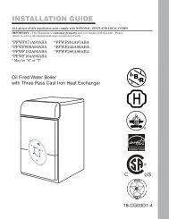
Boiler PipingSECTION IV - Boiler PipingGeneral Piping Requirements- All plumbing must meet or exceed all local,state and national plumbing codes.- Support all piping using hangers. DO NOTsupport piping by the unit or its components.- Use isolation valves to isolate system components.- Install unions for easy removal of thePRESTIGE <strong>Solo</strong> from the system piping.WARNINGUse a two wrench method when tighteningpiping onto the boiler connections.Use one wrench to prevent the boilerpiping from turning / twisting. Failureto support the boiler piping and connectionsin this manner could cause damageto the boiler and its components.Pressure Relief Valve1. The PRESTIGE <strong>Solo</strong> is supplied with a 30psi pressure relief valve and must be pipedusing the PRV connection as shown in Fig.5 page 15.2. To avoid potential water damage to the surroundingarea or potential scalding hazarddue to the operation of the relief valve, thedischarge piping:- Must be connected to the discharge outletof the relief valve and directed to asafe place of disposal.- Length should be as short and direct aspossible. The size of the discharge lineshould not be reduced, maintain thesame size as the outlet of the relief valve.- Should be directed downward towardsthe floor at all times. The piping shouldterminate at least 6 inches [153 mm]above any drain connection to allowclear visibility of the discharge.- Should terminate with a plain end, notwith a threaded end. The material ofthe piping should have a serviceabletemperature rating of 250ºF or greater.- Should not be subject to conditionswhere freezing could occur.- Should not contain any shut-off valvesor obstructions. No shut-off valveshould be piped between the boiler andrelief valve.WARNINGFailure to comply with the guidelines on<strong>install</strong>ing the pressure relief valve anddischarge piping can result in personalinjury, death or substantial propertydamage.Low Water Cutoff Device- The PRESTIGE <strong>Solo</strong> is equipped with a factory<strong>install</strong>ed pressure switch type Low WaterCut Off device.- The minimum operating system pressureallowable with this device is 10 psig.- Check local codes if a Low Water CutoffDevice is required. If so, determine if thisdevice meets the requirements of the localcodes.NOTICEThe PRESTIGE <strong>Solo</strong> control system alsosenses the system water temperaturesentering and exiting the heat exchangerto provide protection against low waterconditions Where local codes and jurisdictiondo not accept a pressure devicefor low water protection, the jurisdictionsmay accept these PRESTIGE <strong>Solo</strong>integral control functions as a means ofproviding low water protection.14
Boiler PipingPressure Relief Valve(Supplied with Boiler)3/4" Street ElbowAir VentDrain Piping Directedto a SuitablePlace of DrainageBoiler SupplyConnectionBoiler Return Connectionwith Tee Fitting andBoiler Drain ValveFig. 5:Pressure Relief Valve and Boiler Drain Valve Installation15
Boiler PipingAdditional Limit ControlIf a separate LWCO device is required by certainlocal jurisdictions or when the boiler is<strong>install</strong>ed above the system piping, the followingguidelines must be followed:- The LWCO device must be designedfor water <strong>install</strong>ations, electrode probetypeis recommended.- The LWCO device must be <strong>install</strong>ed ina tee connection on the boiler supplypiping above the boiler.- Wiring of the LWCO device to the PRES-TIGE <strong>Solo</strong> is done directly onto the lowvoltage terminal strip, reference Fig. 19page 31 for available terminals for anexternal limit (<strong>manual</strong> or auto reset).If the <strong>install</strong>ation is to comply with ASME orCanadian requirements, an additional hightemperature limit may be needed. Consultlocal code requirements to determine compliance.The limit should be <strong>install</strong>ed as follows:- Install the limit in the boiler supply pipingbetween the boiler and any isolationvalve.- Maximum set point for the limit is194ºF.- For wiring of the limit reference Fig. 19,page 31, using the external limit/<strong>manual</strong>reset terminals on the low voltage terminalstrip. This will provide a "hard"lockout requiring a <strong>manual</strong> reset of thecontrol.Backflow Preventer- Use a backflow preventer valve in themake-up water supply to the unit asrequired by local codes.Boiler System Piping ApplicationsBEST PRACTICEIt is recommended on all piping applicationsto utilize a primary/secondary pipingarrangement as a means to provide freezeprotection of the boiler, which is an integralfunction of the boiler control. Maintain theminimum boiler flow rate, see Graphs 2through 7 on pages 91 through 93. Forother piping arrangements, consult theEngineering Department at Triangle Tubeor consult other approved/recognizeddesign arrangements.BEST PRACTICEOn piping applications utilizing a singlezone or other recognized piping designarrangements, it is recommended that the<strong>install</strong>er uses flow/check valves withweighted seats at or near the appliance toprevent gravity circulation.Expansion Tank and Makeup WaterEnsure the expansion tank is properly sized forthe boiler volume (3 gallons [12 L] for thePRESTIGE <strong>Solo</strong> 60, 5 gallons [19 L] for thePRESTIGE <strong>Solo</strong> 175/250, 7 gallons [26 L] forPRESTIGE <strong>Solo</strong> 399) and the system volumeand temperature.CAUTIONUndersized expansion tanks will causesystem water to be lost through the pressurerelief valve and cause additionalmakeup water to be added to the system.Eventual boiler heat exchanger failurecan result due to this excessive makeupwater addition.The expansion tank must be located as shownin Fig. 7 and Fig. 8 on page 19 when using aprimary/secondary piping arrangement or asper recognized design methods. Refer to theexpansion tank manufacturer instructions foradditional <strong>install</strong>ation details.16
Boiler PipingConnect the expansion tank to an air separatoronly if the air separator is located on the suctionside (inlet) of the system circulator.Always locate and <strong>install</strong> the system fill connectionat the same location as the expansiontank connection to the system.Diaphragm Expansion TankAlways <strong>install</strong> an automatic air vent on the topof the air separator to remove residual air fromthe system.Closed-Type Expansion TankIt is recommended to pitch any horizontal pipingupwards toward the expansion tank 1 inch per 5feet of piping. Use 3/4” piping for the expansiontank to allow air within the system to rise.CAUTIONDO NOT <strong>install</strong> automatic air vents on aclosed-type expansion tank system. Airmust remain in the system and bereturned to the expansion tank to providean air cushion. An automatic airvent would cause air to be vented fromthe system resulting in a water-loggedexpansion tank.CirculatorThe PRESTIGE <strong>Solo</strong> requires an external circulatorto provide circulation through the boiler. Thecirculator when wired directly to the PRESTIGE<strong>Solo</strong> will allow for domestic hot water priority andto provide circulation for the freeze protection featureof the boiler control. See Graphs 2 through 7on pages 91 & 93 for pressure drop and minimumflow rate through the boiler.Sizing Primary PipingSee Fig. 9 through 13, pages 21 - 23, for recommendedpiping arrangements based on variousapplications. Size the piping and systemcomponents required in the space heating system,using recognized design methods.Domestic Hot Water System PipingSee Fig. 9 through 12, page 21-22 for recommendedpiping to a DHW system. This recommendedpiping configuration ensures priority isgiven to the production and recovery of the DHW.The piping for the DHW is separate from theboiler system piping and does not require a primary/ secondary piping configuration.To wire the DHW circulator to the boiler controlmodule, reference Section VIII - External Wiring.System Piping - Zone CirculatorsConnect the PRESTIGE <strong>Solo</strong> to the systempiping as shown in Fig. 9 page 21 when zoningwith zone circulators.The <strong>install</strong>er must provide a separate circulatorfor each zone of space heating as well as theboiler circulator.NOTICETo ensure an adequate flow rate throughthe PRESTIGE <strong>Solo</strong>, the boiler supply andreturn piping size must be a minimum of 1inch for the PRESTIGE <strong>Solo</strong> 60, 1-1/4 inchfor the PRESTIGE <strong>Solo</strong> 175/250 and 1-1/2inch for the PRESTIGE <strong>Solo</strong> 399.System Piping - Zone ValvesConnect the PRESTIGE <strong>Solo</strong> to the system pipingas shown in Fig. 10 page 21 when zoningwith zone valves. The primary / secondary pipingensures that the boiler loop has sufficient flow.NOTICETo ensure an adequate flow rate throughthe PRESTIGE <strong>Solo</strong>, the boiler supplyand return piping size must be a minimumof 1 inch for the PRESTIGE <strong>Solo</strong> 60,1-1/4 inch for the PRESTIGE <strong>Solo</strong>175/250 and 1-1/2 inch for the PRESTIGE<strong>Solo</strong> 399.17
Boiler PipingFig. 6: Piping Component Legend18
Boiler PipingFig. 7: Near Boiler Piping - Diaphragm Expansion TankNote: Pitch horizontal pipingupwards (1” of pitchper 5 ft of piping) towardsexpansion tank.Fig. 8 : Near Boiler Piping - Closed Type Expansion Tank19
Boiler PipingSystem Piping - Through BoilerIn new or retrofit applications in whichprimary/secondary arrangement is not utilized, thePRESTIGE <strong>Solo</strong> allows this flexibility due to alower boiler pressure drop, see Graphs 2 through7 on pages 91 through 93.Figure 11, page 22 illustrates a multiple zonevalve system with a single system/boiler circulator.A by-pass loop with a pressure differentialvalve must be <strong>install</strong>ed on the system piping.Figure 12, page 22 illustrates a single zone utilizingthe boiler circulator as the system circulator.System Piping - Radiant HeatingThe heat exchanger design of the PRESTIGEallows operation in a condensing mode. Thisfeature requires no regulation of the returntemperature back to the boiler in radiant heatingapplications.The design and construction of the PRESTIGEheat exchanger allows the <strong>install</strong>ation of the boileron systems with non - oxygen barrier tubing.CAUTIONDO NOT <strong>install</strong> a SMART tank alongwith the PRESTIGE in systems withnon-oxygen barrier tubing. Failure tocomply could result in premature failureof the SMART tank.The boiler water supply temperature can bemaintained by the PRESTIGE, eliminatingthe need for a mix system to achieve thedesired temperature.It is recommended for the <strong>install</strong>er to a hightemperature limit to ensure that the primarysupply temperature does not exceed the maximumallowable temperature for the radianttubing.Size the system piping and circulator to providethe flow needed for the radiant system.NOTICETo ensure an adequate flow rate throughthe PRESTIGE <strong>Solo</strong>, the boiler supplyand return piping size must be a minimumof 1 inch for the PRESTIGE <strong>Solo</strong> 60,1-1/4 inch for the PRESTIGE <strong>Solo</strong>175/250 and 1-1/2 inch for the PRESTIGE<strong>Solo</strong> 399.NOTICEThe addition of the high temperature limitis important if the PRESTIGE is connectedto a domestic hot water system, whichrequires a high primary supply watertemperature.System Piping - Special ApplicationIf the boiler is used in conjunction with achilled water/medium system, the boiler andchiller must be piped in parallel. Installflow/check valves to prevent the chilled mediumfrom entering into the boiler.If the boiler is used to supply hot water to theheating coils of an air handler where they maybe exposed to chilled air circulation, <strong>install</strong>flow/check valves or other automatic meansto prevent gravity circulation of the boilerwater during cooling cycles.System Piping - Multiple Units InstallationUse a balanced manifold system as the primary/ secondary connection to the space heatingpiping as shown in Fig. 13 page 23.Maintain a minimum of 6 inches [153 mm] ofclearance between units to allow for servicing.Refer to Figs. 7 and 8 page 19 to <strong>install</strong> air separatorand expansion tank.For the space heating piping refer to the applicationsmentioned in this <strong>manual</strong> or use recognizeddesign methods.20
Boiler PipingNote: Reference Fig. 23, page 38 for<strong>Prestige</strong> Wiring.Fig. 9: System Piping - Zoning with Zone CirculatorsNote: Reference Fig. 24, page 38 for<strong>Prestige</strong> Wiring.Fig. 10: System Piping - Zoning with Zone ValvesNOTICEThe boiler system piping shown must be a “closed” system to avoid anyoxygen contamination and potential failure of the outer tank of the Smart.21
Boiler PipingNote: Reference Fig. 25, page 39 for<strong>Prestige</strong> Wiring.Note: Verify CH circulator isproperly sized to overcome thesystem pressure drop and provideadequate flow through theboiler system.Fig. 11: System Piping - Multiple Zone Valve with Single System/Boiler CirculatorNote: Reference Fig. 26, page 39 for<strong>Prestige</strong> Wiring.Note: Verify CH circulatoris properly sized toovercome the system pressuredrop and provide adequateflow through theboiler system.Fig. 12: System Piping - Single Zone System with Single System/Boiler CirculatorNOTICEThe boiler system piping shown must be a “closed” system to avoid anyoxygen contamination and potential failure of the outer tank of the Smart.22
Boiler PipingFig. 13: Multiple PRESTIGE <strong>Solo</strong> Boiler Piping - Primary / SecondaryNote: Consult the PRESTIGETriMax Control Supplement forinformation on wiring and configuringthe boilers using thebuilt-in Cascade function23
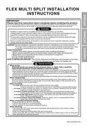
Installing Vent/Combustion Air & Condensate DrainSECTION V - Installing Vent /Combustion Air & Condensate DrainInstalling Vent and Combustion AirDANGERThe PRESTIGE <strong>Solo</strong> must be ventedand supplied with combustion air asshown in the PRESTIGE <strong>Solo</strong> VentSupplement, included in the boiler<strong>install</strong>ation envelope. Refer to optionalvent kit instructions for additional vent<strong>install</strong>ation instructions. Once <strong>install</strong>ationis completed, inspect the vent andcombustion air system thoroughly toensure systems are airtight and complywith the instructions given in the ventingsupplement and are within all requirementsof applicable codes. Failure tocomply with the <strong>install</strong>ation requirementson the venting and combustion airpiping will cause severe personal injuryor death.Installing Condensate Drain Assembly1. Locate the condensate drain assembly and<strong>install</strong> as shown in Fig. 14 page 25.NOTICEThe <strong>install</strong>er may want to fill the condensatetrap with water prior to assemblingon the unit.2. Remove the retaining nut and rubber sealfrom the condensate drain assembly andslide over the heat exchanger condensatedrain nipple. Connect the condensate drainassembly to the retaining nut and tighten.Hand tight only!WARNINGEnsure the condensate drain assemblycontains the plastic seated ball. Do not<strong>install</strong> the condensate drain assembly ifthe ball is lost or missing, replace theentire assembly.3. Remove the compression nut and rubberseal from the drain outlet.4. Using 3/4” x 2’ flexible PVC tube provided,slide the compression nut and rubberseal over the pipeNOTICEThe use of 3/4” PVC or CPVC pipe isalso acceptable. If 3/4” pipe is useddeburr and chamfer pipe to allow matingonto the drain assembly.5. Thread the rubber seal into the compressionnut to ease <strong>install</strong>ation of the pipe tothe drain assembly.6. Seat the pipe onto the drain assembly andtighten the compression nut. Hand tightonly!NOTICEThe <strong>install</strong>er may opt to using 13/16" IDtubing in lieu of rigid piping.NOTICEThe drain line materials must be anapproved material by the authority havingjurisdiction. In absence of suchauthority, PVC and CPVC piping mustcomply with ASTM D1785 or D2845.The cement and primer used on the pipingmust comply with ASME D2564 orF493. For <strong>install</strong>ations in Canada, useCSA or ULC certified PVC or CPVCpipe, fittings and cement/primer.7. Continue the pipe from the drain assemblyto a floor drain or condensate pump.24
Installing Vent/Combustion Air & Condensate DrainNOTICEWhen selecting and <strong>install</strong>ing a condensatepump, ensure the pump is approvedfor use with condensing boilers and furnaces.The pump should be equippedwith an overflow switch to prevent propertydamage from potential condensatespillage.8. The PRESTIGE <strong>Solo</strong> will typically producea condensate that is considered slightlyacidic with a pH content below 3.0. Installa neutralizing filter if required by authorityhaving jurisdiction.CAUTIONThe condensate drain must remain filledand unobstructed and allow unrestrictedflow of condensate. The condensateshould not be subject to conditionswhere freezing could occur. If the condensateis subjected to freezing orbecomes obstructed , it can leak, resultingin potential water damage to the boilerand surrounding area.Fill Plugwith VaccumBreak PortHeat ExchangerCondensateDrain NippleCompressionNut with Rubber SealRetaining Nutwith Rubber Seal(Hand Tight Only)Plastic BallFlexible Tubing(or 3/4 PVC/CPVC Pipingto Drain)CondensateDrain AssemblyFig. 14: Condensate Drain Assembly25
Gas PipingSECTION VI - Gas PipingGas Supply Piping ConnectionNOTICEThe gas supply piping must be <strong>install</strong>edin accordance to all applicable local,state and national codes and utilityrequirements.1. Install a 1/2” NPT for PRESTIGE <strong>Solo</strong> 60,3/4” NPT for PRESTIGE <strong>Solo</strong> 175/250 or1” NPT for PRESTIGE <strong>Solo</strong> 399 pipeunion at the factory supplied gas nipple, forease of service.2. Install a <strong>manual</strong> shutoff valve in the gassupply piping as shown in Fig. 15. For<strong>install</strong>ations in Canada the <strong>install</strong>er musttag and identify the main shutoff valve.3. Install a sediment trap (drip leg) on the gassupply line prior to connecting to the PRES-TIGE <strong>Solo</strong> gas train as shown in Fig. 15.4. Support the gas piping using hangers. Donot support the piping by the unit or itscomponents.5. Purge all air from the gas supply piping.6. Before placing the PRESTIGE <strong>Solo</strong> intooperation, check and test all connectionsfor leaks.- Close the <strong>manual</strong> shutoff valve duringany pressure test with less than 13”w.c..- Disconnect the PRESTIGE <strong>Solo</strong> and itsgas valve from the gas supply pipingduring any pressure test greater than13”w.c..WARNINGDo not check for gas leaks with an openflame. Use a gas detection device or bubbletest. Failure to check for gas leakscan cause severe personal injury, deathor substantial property damage.7. Use pipe dope compatible with natural andpropane gases. Apply sparingly only to themale threads of pipe joints so that pipedope does not block gas flow.WARNINGFailure to apply pipe dope as detailedabove can result in severe personalinjury, death or substantial propertydamage.WARNINGUse a two-wrench method of tighteninggas piping near the unit and its gas pipingconnection. Use one wrench to preventthe boiler gas line connection fromturning and the second to tighten adjacentpiping. Failure to support the boilergas piping connection could damagethe gas line components.External ManualGas Shut OffValve (Must BeWithin 6' of theBoiler)Tee FittingSedimentTrap Min.Length of 3"Gas FlowCapUnion FittingFig. 15: Recommended Gas Supply Piping26
Gas PipingNATURAL GASPipe Sizing - Natural GasRefer to Table 1 for schedule 40 metallic pipelength and diameter requirements for naturalgas, based on rated PRESTIGE <strong>Solo</strong> input(divide by 1,000 to obtain cubic feet per hour).- Table 1 is based on Natural Gas with a specificgravity of 0.60 and a pressure dropthrough the gas piping of 0.30”w.c..- For additional gas piping sizing information,refer to ANSI Z223.1. For Canadian<strong>install</strong>ations refer to B149.1 or B149.2.Natural Gas Supply Pressure Requirements1. Pressure required at the gas valve inletsupply pressure port:- Maximum 13”w.c. at flow or no flowconditions to the burner.- Minimum 5”w.c. during flow conditionsto the burner. Must be verified duringstart up and with all other gas appliancesoperating within the building.2. Install 100% lockup gas pressure regulatorin the gas supply line if inlet pressure canexceed 13”w.c at any time. Adjust the lockuppressure regulator for 13”w.c maximum.WARNINGDO NOT adjust or attempt to measuregas valve outlet pressure. The gas valveis factory-set for the correct outlet pressure.This setting is suitable for naturalgas and propane and requires no fieldadjustment. Attempts by the <strong>install</strong>er toadjust or measure the gas valve outletpressure could result in damage to thevalve, causing potential severe personalinjury, death or substantial propertydamage.NOTICEThe natural gas orifice requirements are:PRESTIGE <strong>Solo</strong> 60: 0.204” (5.2 mm)PRESTIGE <strong>Solo</strong> 175: None RequiredPRESTIGE <strong>Solo</strong> 250: None RequiredPRESTIGE <strong>Solo</strong> 399: 0.339” (8.6 mm)Table 1: Gas Piping Sizing - Natural GasLength of Pipe inFeetCapacity of Schedule 40 Metallic Pipe in Cubic Feet of Natural Gas PerHour (based on 0.60 specific gravity, 0.30" w.c. pressure drop)SCH 40 1/2" 3/4" 1" 1-1/4" 1-1/2"10 132 278 520 1050 160020 92 190 350 730 110030 73 152 285 590 89040 63 130 245 500 76050 56 115 215 440 67075 45 93 175 360 545100 38 79 150 305 460150 31 64 120 250 38027
Gas PipingPROPANE GASPipe Sizing - Propane GasContact the local propane gas supplier for recommendedsizing of piping, tanks and 100%lockup gas regulator.Propane Gas Supply Pressure Requirements1. Adjust the propane supply regulator providedby the gas supplier for 13”w.c. maximumpressure2. Pressure required at the gas valve inlet supplypressure port:- Maximum 13”w.c. at flow or no flowconditions to the burner- Minimum 5”w.c. during flow conditionsto the burner. Must be verified duringstart up and with all other gas appliancesoperating within the building.WARNINGPrior to start up, ensure the unit is set tofire propane. Check the rating label forthe type of fuel. Check the gas valve forpropane conversion label. If there is aconflict or doubt on the burner set up,remove the gas valve and check for thepropane orifice, see Fig. 16 or 17, page29. Failure to ensure proper burnersetup could result in severe personalinjury, death or substantial propertydamage.NOTICEThe propane orifice requirements are:PRESTIGE <strong>Solo</strong> 60: 0.120” (3.1 mm)PRESTIGE <strong>Solo</strong> 175: 0.221” (5.6 mm)PRESTIGE <strong>Solo</strong> 250: 0.250” (6.3 mm)PRESTIGE <strong>Solo</strong> 399: 0.264” (6.7 mm)WARNINGDO NOT adjust or attempt to measuregas valve outlet pressure. The gas valveis factory-set for the correct outlet pressure.This setting is suitable for naturalgas and propane and requires no fieldadjustment. Attempts by the <strong>install</strong>er toadjust or measure the gas valve outletpressure could result in damage to thevalve, causing potential severe personalinjury, death or substantial propertydamage.28
Gas PipingGas ValveGasketOrificeGas ValveVenturiFig. 16: Gas Valve / Venturi Assembly - PRESTIGE <strong>Solo</strong> 60/175/250GasketsOrificeVenturiGas ValveFig. 17: Gas Valve / Venturi Assembly - PRESTIGE <strong>Solo</strong> 39929
Internal WiringSECTION VII - Internal WiringWARNINGELECTRICAL SHOCK HAZARD. Foryour safety, disconnect electrical powersupply to the unit before servicing ormaking any electrical connections toavoid possible electric shock hazard.Failure to do so can cause severe personalinjury or death.General Requirements- Wiring must be N.E.C Class 1.- If original wiring as supplied with the unitmust be replaced, use only Type T 194ºF[90ºC] wire or equivalent as a minimum.- The PRESTIGE must be electricallygrounded as required by NationalElectrical Code ANSI/NFPA 70 - latest editionand / or the Canadian Electrical CodePart 1, CSA C22.1, Electrical Code.CAUTIONPrior to servicing, label all wires beforedisconnecting. Wiring errors can causeimproper and dangerous operation.Verify proper wiring and operation afterservicing.30
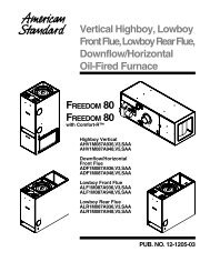
Internal WiringTriMaxDisplayModule<strong>Prestige</strong> <strong>Solo</strong> Internal Wiring923X01781YYYYYYYYYYYY123456X07365GYYBR3 X06 W3 GND4 2WFlue Temperature SensorYWGas Valve Gas ValveY(<strong>Solo</strong> 399 only) (All except <strong>Solo</strong> 399)7 RSupply Temperature SensorR8 RR 136 BLReturn Temperature SensorBL1 BLBL 12X044 WLWCOO5 WO10 BKV9 BKV 112 BKBR3 BKBR 141 WO2 WOX033 W1 BK4 WBlower 2 R5 WBlowerSignal Terminals 4 BL6 W5 W3GNDBlower2BKPower Terminals1W 10BKWBKWBKW 9V1V1GV2V2GND6575563451BKWBKW1582438621727384X05213412BKBKRRBKWWire Legend- Low Voltage- Line Voltage- Ignition CableBK BK BK BK W W V V BR BR O O BL BL R R W W W BR Y GY BK W BK W BK W BK W BK W R ROn / OffSwitch1 2CH1Thermostat3 4CH2Thermostat5 6OutdoorSensor7 8DHWAquastator Sensor9 10ManualResetLimit11 12AutoResetLimit13 14+ -ModulationSignal15 16SystemSensor17 18 19CascadeMaster20 21 22A B GModbus23 24 25 26 27 28 29* 30 31* 32* 33 34 35 36 37 38 39 40L G NCH2 Pump /System PumpL G NAuxiliaryBoiler PumpL G NDHW Pump /*Diverter ValveL G NPower SupplyAlarmCascadeSlaveWire Color LegendBK – BlackW – WhiteGR – GreenBL – BlueR – RedO – OrangeV – VioletY – YellowBR – BrownGY - GrayNotes:1. If any of the original wire supplied with the appliance must be replaced, it must be replaced with the same type or its equivalent.2. All 120 VAC field wiring to the boiler shall have a minimum size of 14 AWG with a temperature rating of at least 194°F [90°C].Circulator factorywired on <strong>Prestige</strong><strong>Solo</strong> 110 only.Circulator TerminalsLGNL G NCH (1) Pump /*Diverter ValveTriMaxControlModuleX15X02X14X13X11X01X00F00GNDGNDIgnitorFig. 19: <strong>Prestige</strong> <strong>Solo</strong> Boiler Factory Wiring31
External WiringSECTION VIII- External WiringInstallation ComplianceAll field wiring made during <strong>install</strong>ation mustcomply with:- National Electrical Code NFPA 70 and anyother national, state, provincial or localcodes or requirements.- In Canada, CSA C22.1 Canadian ElectricalCode Part 1, and any other local codes.WARNINGELECTRICAL SHOCK HAZARD.Before making any electrical connectionsto the PRESTIGE, disconnect electricalpower supply at the service panel.Failure to comply can cause severe personalinjury or death.NOTICEThe line voltage terminals are located onthe right set of terminals 23 through 40.The low voltage terminals are located onthe left set of terminals 1 through 22.Line Voltage Connections1. Connect a dedicated 120 VAC/15A serviceto the line voltage terminal strip on thewiring panel below the PRESTIGE controlmodule, as shown in Fig. 19, page 31.2. Route the incoming 120 VAC power wirethrough the provided openings in the bottomjacket panel.3. The unit is provided with a service switchlocated on the front panel, check local coderequirements for compliance.NOTICEIf local electrical codes or conditionsrequire an additional service switch, the<strong>install</strong>er must provide and <strong>install</strong> a fuseddisconnect or 15 amp (minimum) serviceswitch.Circulator Wiring1. Reference Table 2 to determine the appropriatecirculator connections required. Thecirculator connections used will depend onthe systems piping layout.CH 1 orCH 2 CallDHW CallNote1: Domestic Hot Water Priority can be disabledin the Installer Menu which allowsthe CH (1) and DHW circulators to operateat the same time. Consult the PRES-TIGE TriMax Control Supplement formore information.Note2:The system circulator can also beenabled during a DHW Call in theInstaller Menu. Consult the PRESTIGETriMax Control Supplement for moreinformation.NOTICECH (1)PumpONDHWPumpAuxillaryBoilerPumpSystemPumpOFF(Note 1)ON ONOFF(Note 1)ON ONOFF(Note 2)Each circulator is individually fusedwith a 2.5A fuse located in the terminalstrip. The total combined amp draw ofthe CH (1), DHW, and Auxiliary BoilerCirculators must not exceed 4 amps atany time for the <strong>Solo</strong> 60, 175, or 250.The total combined amp draw of the CH(1), DHW, and Auxiliary BoilerCirculators must not exceed 3 amps atany time for the <strong>Solo</strong> 399. Use an isolationrelay to lower the total combinedamp draw if exceeding these limits.2. Connect the CH circulator to the line voltageterminal strip on the wiring panelbelow the PRESTIGE control module, asshown in Fig. 19 on page 31. The CH circulatoris enabled during a CH 1 or CH 232
External Wiringcall. This circulator is used to supply heatto the central/space heating loop.3. Connect the DHW circulator to the linevoltage terminal strip on the wiring panelbelow the PRESTIGE control module, asshown in Fig. 19 on page 31. The DHWcirculator is enabled during a DHW call.This circulator is used to supply heat to anindirect hot water heater.4. Connect the Auxiliary Boiler circulator tothe line voltage terminal strip on the wiringpanel below the PRESTIGE control module,as shown in Fig. 19 on page 31. Theauxiliary boiler circulator is enabled duringa CH or a DHW call. This circulator is typicallyused in retrofit applications wherethe CH and DHW systems are connected toa common boiler supply.5. Connect the System circulator to the linevoltage terminal strip on the wiring panelbelow the PRESTIGE control module, asshown in Fig. 19 on page 31. The systemcirculator is enabled during a CH1 or CH2call with the factory default TriMax settings.This circulator is typically used tocirculate water in the secondary CH loopwhen zoning with zone valves.Alarm WiringThe alarm contact closes whenever the<strong>Prestige</strong> is in a soft or hard lockout. Thisdry contact can be connected to an externalmonitoring system or other indicator to alertthe operator that the <strong>Prestige</strong> is locked out.1. Connect the external monitoring device tothe line voltage terminal strip on the wiringpanel below the PRESTIGE control module,as shown in Fig. 19 on page 31.NOTICEThe alarm contact is fused with a 2.5Afuse located in the terminal strip. An isolationrelay is required if the externalmonitoring device draws more than 2.5A.Low Voltage ConnectionsNOTICELine and Low Voltage wiring should beseparated to prevent possible electricalnoise on the low voltage circuits. Lineand Low Voltage wiring should use separateelectrical knockouts on the PRES-TIGE cabinet and should remain separatedinside the PRESTIGE.NOTICECH and DHW call connections to thePRESTIGE require a dry contact with noexternal voltage present. Ensure no externalvoltage is present on each set of wiresbefore connecting to the PRESTIGE. Ifexternal voltage is present, the use of anisolation relay is required to prevent damageto the TriMax controller.Thermostat WiringThe TriMax control has two thermostat call inputsfor multiple zone / temperature systems. Thisallows each call to have its own outdoor resetcurve and maximizes the efficiency of the system.WARNINGSimultaneous CH1 and CH2 calls willresult in the PRESTIGE operating at thehighest target temperature. The use of amixing device on the lower temperaturezones such as the Triangle Tube OptimaSeries SMV Control may be required toprotect the lower temperature zonesfrom damage.1. Connect the room thermostat or dry contactend switch to the low voltage terminal stripon the wiring panel below the PRESTIGEcontrol module, as shown in Fig. 19 onpage 31.33
External Wiring2. Follow thermostat manufacturer’s instructionsfor proper <strong>install</strong>ation. Thermostatshould be located on an inside wall awayfrom any heat or cold influences such asdrafts, lights, fireplaces, etc.3. Set the thermostat anticipator (If applicable)as follows:- Set for 0.2 amps when wired directly tothe PRESTIGE.- Set to match the electrical powerrequirements of the connected devicewhen wired to zone relays or otherdevices. Refer to the relay manufacturer’sspecifications and the thermostatinstructions for additional informationon anticipator setting.NOTICEThe use of power stealing thermostatswhich draw their power from the PRES-TIGE can lead to erratic or unpredictableoperation. Honeywell T87 seriesthermostats are excluded from thisnotice since they are designed to operatewith the TriMax control.Outdoor Sensor WiringThe Outdoor Reset function and WarmWeather Shutdown (WWSD) features requirethe connection of the included outdoor temperaturesensor. See page 63 for outdoor sensor<strong>install</strong>ation and setup.Domestic Hot Water WiringThe Domestic Hot Water terminals can accepteither a call from an aquastat (switch) or temperaturesensor. Use of the included indirectwater heater sensor is recommended.1. Connect the DHW aquastat or temperaturesensor to the low voltage terminal strip onthe wiring panel below the PRESTIGE controlmodule, as shown in Fig. 19 on page 31.Additional Boiler LimitsAdditional boiler limits (High Limit, LWCO,etc.) can be wired into either the Manual ResetLimit or Auto Reset Limit terminals of thePRESTIGE. These limit connections will providea “hard” lockout requiring a <strong>manual</strong> resetof the PRESTIGE or a “soft” lockout in whichthe PRESTIGE will automatically reset whenthe limit resets.NOTICEManual Reset Limit and Auto ResetLimit connections to the PRESTIGErequire a dry contact with no externalvoltage present. Ensure no external voltageis present on each set of wires beforeconnecting to the PRESTIGE. If externalvoltage is present, the use of an isolationrelay is required to prevent damageto the TriMax controller.1. Remove the factory <strong>install</strong>ed jumper wireon the Manual Reset or Auto Reset terminalsthat will accept the additional boilerlimit.2. Connect the additional boiler limit to thelow voltage terminal strip on the wiringpanel below the PRESTIGE control module,as shown in Fig. 19 on page 31.External Modulation ControlThe PRESTIGE firing rate can be controlled byan external modulating boiler controller. Seepage 64 for external modulation signal wiringand setup.System Sensor WiringAn optional system temperature sensor can beplaced on the central heating loop to control thetemperature in the central heating loop insteadof the boiler loop. When connected, the PRES-TIGE will automatically modulate to maintainthe target temperature in the central heatingloop. The boiler supply temperature sensorwill continue to be used as a high temperaturelimit.34
External WiringCAUTIONLocate the system temperature sensorwhere it can accurately measure the supplytemperature to the heating system.Inaccurate system temperature readingscould lead to overheating or under heatingresulting in property damage.1. Connect the system temperature sensor tothe low voltage terminal strip on the wiringpanel below the PRESTIGE control module,as shown in Fig. 19 on page 31.Cascade WiringThe TriMax control includes the ability tooperate up to six boilers together as one withoutthe need for external controllers. Consultthe PRESTIGE TriMax Control Supplementfor more information.Modbus WiringThe TriMax control includes the ability tocommunicate with building management systems(BMS) through a Modbus interface.Consult the PRESTIGE TriMax ControlSupplement for more information.35
External WiringFig. 20: Multiple Zone Field Wiring Using Zone Valves36
External WiringFig. 21: Multiple Zone Field Wiring using Zone Circulators37
External WiringNote: Reference Fig. 9, page 21 forSystem Piping.Fig. 23: <strong>Prestige</strong> Wiring - Zoning with Zone CirculatorsNote: Reference Fig. 10, page 21 forSystem Piping.Fig. 24: <strong>Prestige</strong> Wiring - Zoning with Zone Valves38
External WiringNote: Reference Fig. 11, page 22 forSystem Piping.CascadeSlaveCH1T-statCH2T-statOutdoorSensorLow voltage terminal stripDHW Manual AutoStat/SensReset/lmtReset/lmtModulationSignal+ -SystemSensorCascadeMasterModbusA B GCH2 / SysPumpL G NLine voltage terminal stripAux Boiler DHW Pump / CH1 Pump PowerPump Divert Valve Diverter Valve SupplyL G N L G N L G N L G NAlarmContact1 2 3 4 5 6 7 8 910111213141516171819202122 232425262728293031323334353637383940Zone #1 Zone ValveEnd SwitchZone #2 Zone ValveEnd SwitchOutdoor SensorC 2 1Smart TankSnap SetDHW AquastatDC1HC1 120V/15AServiceFig. 25: <strong>Prestige</strong> Wiring - Multiple Zone Valve with Single System/Boiler CirculatorNote: Reference Fig. 12, page 22 forSystem Piping.CascadeSlaveCH1T-statCH2T-statLow voltage terminal stripModulationOutdoor DHW Manual AutoSignalSensor Stat/SensReset/lmtReset/lmt + -SystemSensorCascadeMasterModbusA B GCH2 / SysPumpL G NLine voltage terminal stripAux Boiler DHW Pump / CH1 Pump PowerPump Divert ValveDiverter Valve SupplyL G N L G N L G N L G NAlarmContact1 2 3 4 5 6 7 8 910111213141516171819202122 23242526272829303132333435363738394068Room ThermostatOutdoor SensorC 2 1Smart TankSnap SetDHW AquastatDC1HC1 120V/15AServiceFig. 26: <strong>Prestige</strong> Wiring - Single Zone System with Single System/Boiler Circulator39
TriMax OperationSECTION IX- TriMax OperationThe TriMax Boiler Management System is designed to be flexible yet easy to use. TriMax monitorsand controls the <strong>Prestige</strong> to provide heat as efficiently as possible. TriMax includes manyadvanced features which previously were not available in the <strong>Prestige</strong>.• Two central/space heating (CH) call inputs with separate outdoor reset curves.• Domestic Hot Water (DHW) call input with optional priority.• EZ Setup feature allows the <strong>install</strong>er to quickly customize TriMax for each <strong>install</strong>ation.• Cascade function allows up to six <strong>Prestige</strong> boilers to operate together in a single heating system.• Modbus interface for integrating with building management systems.All TriMax features are easy to use through a graphical display where information is presentedeither graphically or in plain English, so code charts are not required. Figure 30 shows a TriMaxdisplay example of the <strong>Prestige</strong> fired for a domestic hot water demand.Fig. 30: TriMax User Interface40
abc de f bbb babc de f bbabc deabc de f bbb babc de f bbf bg abc dTriMax OperationTriMax Menu StructureHome ScreenMain MenuEZ Setup MenuCH/DHW Operation MenuBoiler Information MenuHeating EnabledBoiler Informationbbbbbbfdededeabcabcabcbbbbbbffdededabcabcabc42
TriMax OperationHome ScreenThe Home Screen presents status information in a very user friendly way so that the currentstate of the boiler can be quickly accessed.The <strong>Prestige</strong> is represented in the center of the Home Screen. Basic operatinginformation such as supply and return temperatures are displayed as well ascurrent burner status. A flame symbol is displayed when the unit is fired. Theflame size changes to indicate the current firing rate.The radiator icon indicates that acentral heating call has been received.A small number 1 or 2 indicateswhich CH calls are active.The faucet icon indicates that adomestic hot water call has beenreceived.The percentage icon indicates thatan external modulation call hasbeen received.12Circulator icons indicate whichcirculators are currently powered.This line provides basic information.The user can press the LEFT or RIGHTarrow buttons to view Target, Supply,Return, Domestic and OutdoorTemperatures.The status line displays the current operating state of the <strong>Prestige</strong>.See page 44 for a list of all Status Line Messages.The screen backlight will illuminate when any button is pressed and remain illuminated for fiveminutes. Press the UP or DOWN buttons to turn on the backlight while at the Home Screenwithout making any changes.The screen contrast can be adjusted at the Home Screen by pressing and holding the OK buttonthen pressing and holding the LEFT arrow along with the OK button. The contrast canthen be increased by pressing the UP button or decreased by pressing the DOWN button whileholding in the OK button and LEFT arrow. All buttons must be released and the procedureperformed again to switch between increasing and decreasing contrast.43
TriMax OperationStatus Line MessagesStatus Line MessageStandbyCH DemandDHW DemandCH / DHW DemandDHW PriorityPriority TimeoutExternal DemandSlave OperationManual OperationCH Burner DelayDHW Burner DelayCH Setpoint ReachedDHW Setpoint ReachedCH Post PumpDHW Post PumpFreeze ProtectionBoiler ProtectionLockout DescriptionDescriptionIndicates that the <strong>Prestige</strong> is ready to respond when a demand is received.A central heating call has been received.A domestic hot water call has been received.Central heating and domestic hot water calls are being received simultaneously.Both calls are being satisfied simultaneously because domestic hotwater priority has been disabled.Central heating and domestic hot water calls are being received simultaneously.Domestic hot water call is being satisfied first because it has priorityover central heating calls.Central heating and domestic hot water calls are being received simultaneously.The domestic hot water priority time limit has been exceeded.Priority will now switch back and forth between central heating and domestichot water calls until one call is satisfied.An external modulation call has been received.The <strong>Prestige</strong> is responding to a call from the master <strong>Prestige</strong> boiler in a cascadesystem.The burner or circulators have <strong>manual</strong>ly been enabled in the Installer Menu.The burner will not fire until the call blocking time has elapsed.The burner will not fire until the call blocking time has elapsed.The burner is not fired because the supply/system water temperatureexceeds the setpoint. The central heating circulator continues to operateand the burner will fire again once the supply/system water temperaturedrops below the setpoint.The burner is not fired because the supply/system water temperatureexceeds the setpoint. The domestic circulator continues to operate and theburner will fire again once the supply/system water temperature dropsbelow the setpoint.The central heating circulator is running to remove heat from the <strong>Prestige</strong> atthe completion of a call.The domestic hot water circulator is running to remove heat from the<strong>Prestige</strong> at the completion of a call.The burner is fired because the freeze protection feature has been activated.Freeze protection will end once the supply/system water temperature israised to 60ºF [16ºC].The burner firing rate is being reduced because of an excessive differencebetween the boiler supply and return temperatures. The firing rate willbegin increasing once the temperature difference is less than 45ºF [25ºC].The lockout which currently has the <strong>Prestige</strong> shut down is displayed.44
TriMax OperationMain MenuThe Main Menu can be entered from the Home Screen by pressing the OK button. The menusystem utilizes icons to represent each selection. The currently selected menu is displayedas a reversed image with a text description shown at the top of the display. Menus can beentered by highlighting the desired icon and pressing the OK button.Press OK ButtonCurrently selected menuThe EZ Setup menu canbe accessed by selectingthis icon.The CH / DHW OperationMenu can be accessed byselecting this icon.The Boiler InformationMenu can be accessedby selecting this icon.The Home Screen icon atthe bottom of each screenreturns to the Home Screenwhen selected.The Previous Screen icon at thebottom of each screen returns tothe previous screen when selected.45
TriMax OperationEZ SetupNavigation: Home Screen>Main Menu>EZ SetupThe EZ Setup menus provide a simple way to quickly customize theTriMax for each <strong>install</strong>ation. EZ Setup prompts the user to make selectionswhich allows the <strong>Prestige</strong> to be setup very quickly without searchingthrough long lists of settings and <strong>manual</strong>ly making adjustments.Heating EZ SetupNavigation: Home Screen>Main Menu>EZ Setup>Heating EZ SetupHeating EZ Setup allows the <strong>install</strong>er to quickly customize the central heatingsettings for the application.Select CH DemandDefault: Switch & SetpointSelect CH Demand prompts the <strong>install</strong>er to select how a CH Demand is generated.Press the UP or DOWN buttons to select the CH Demand type thenpress the OK button to store the setting. The Select CH Demand options are:• Switch & Outdoor Reset – This option is only displayed when theoutdoor temperature sensor is connected. A central heating call from athermostat or zone panel will enable the <strong>Prestige</strong> and the setpoint willvary with the outdoor temperature for central heating calls.• Switch & Setpoint - This option is only displayed when the outdoortemperature sensor is not connected. A central heating call from a thermostator zone panel will enable the <strong>Prestige</strong> and the setpoint will befixed for central heating calls• Constant & Outdoor Reset - This option is only displayed when theoutdoor temperature sensor is connected. The <strong>Prestige</strong> will maintain setpointwithout an external call from a thermostat or zone panel. The setpointwill vary with the outdoor temperature for central heating calls.• Constant & Setpoint - The <strong>Prestige</strong> will maintain setpoint without anexternal call from a thermostat or zone panel. The setpoint will be fixedfor central heating calls.• 0-10V Modulation Signal – This option allows the <strong>Prestige</strong> firing rateto be controlled by an external control system.CH1 SetpointDefault: 180°F [82°C]CH1 Setpoint prompts the <strong>install</strong>er to enter the fixed setpoint for a CH1heating call when a Setpoint option is chosen in Select CH Demand. Pressthe LEFT or RIGHT buttons to adjust the CH1 Setpoint then press theOK button to store the setting.Select CH DemandSwitch & Outdoor ResetConstant & Outdoor ResetConstant & Setpoint0-10V Modulation SignalORSelect CH DemandSwitch & SetpointConstant & Setpoint0-10V Modulation SignalCH1 Setpoint180ºF68ºF 194ºFCH2 SetpointDefault: 140°F [60°C]CH2 Setpoint prompts the <strong>install</strong>er to enter the fixed setpoint for a CH2heating call when a Setpoint option is chosen in Select CH Demand. Pressthe LEFT or RIGHT buttons to adjust the CH2 Setpoint then press theOK button to store the setting.46
TriMax OperationSelect CH1 Reset CurveDefaut: Finned Tube BaseboardSelect CH1 Reset Curve prompts the <strong>install</strong>er to select an outdoor reset curvefor a CH1 heating call when an Outdoor Reset option is chosen in Select CHDemand. Outdoor reset curve presets are available to cover most applications.The outdoor reset curve can also be adjusted to any desired settings inthe Installer Menu. Press the UP or DOWN buttons to select the outdoorreset curve appropriate for the type of heating system then press the OK buttonto store the setting.Select CH2 Reset CurveDefault: Low Mass RadiantSelect CH2 Reset Curve prompts the <strong>install</strong>er to select an outdoor reset curvefor a CH2 heating call when an Outdoor Reset option is chosen in Select CHDemand. Outdoor reset curve presets are available to cover most applications.The outdoor reset curve can also be adjusted to any desired settings inthe Installer Menu. Press the UP or DOWN buttons to select the outdoorreset curve appropriate for the type of heating system then press the OK buttonto store the setting.180ºF120ºF64ºF 0ºFCurrent SettingsTable 2: Outdoor Reset Preset SelectionsPreset Minimum Setpoint Maximum SetpointLow Mass Radiant 80ºF [27ºC] 140ºF [60ºC]High Mass Radiant 80ºF [27ºC] 120ºF [49ºC]Cast Iron Baseboard 100ºF [38ºC] 170ºF [77ºC]Finned Tube Baseboard 120ºF [49ºC] 180ºF [82ºC]Radiators 120ºF [49ºC] 170ºF [77ºC]Fan Coil 140ºF [60ºC] 180ºF [82ºC]Set Warm Weather Shutdown TemperatureDefault: OFFWarm Weather Shutdown prompts the <strong>install</strong>er to enter an optional outdoortemperature at which to disable the central heating function. The <strong>Prestige</strong>will continue to respond to a domestic hot water call or a 0-10VModulation Signal when the outdoor temperature exceeds the WarmWeather Shutdown Temperature setting. Press the LEFT or RIGHT buttonsto adjust the Warm Weather Shutdown Temperature then press the OKbutton to store the setting. The Warm Weather Shutdown icon is displayedon the home screen when the outdoor temperature reaches theWarm Weather Shutdown Temperature.Set Warm WeatherShutdown TemperatureOffOff 78ºF47
TriMax OperationDomestic Hot Water EZ SetupNavigation: Home Screen>Main Menu>EZ Setup>DHW EZ SetupDomestic Hot Water EZ Setup allows the <strong>install</strong>er to quickly customize thedomestic hot water settings for the application.Select DHW DemandDefault: SwitchSelect DHW Demand prompts the <strong>install</strong>er to select the type of device whichwill generate a DHW call. Press the UP or DOWN buttons to select theDHW Demand type then press the OK button to store the setting. The SelectDHW Demand options are:• Switch – A domestic hot water call from an aquastat or dry contactswitch will enable the <strong>Prestige</strong> with a fixed setpoint for a domestic hotwater call.• Sensor – This option requires the use of Indirect Water Heater SensorPSRKIT22. The <strong>Prestige</strong> will monitor the DHW storage temperatureand generate a domestic hot water call when the temperature dropsbelow the DHW Storage Setpoint by 6ºF [3ºC].Boiler DHW SetpointDefault: 186°F [86°C]Boiler DHW Setpoint prompts the <strong>install</strong>er to enter the fixed boiler setpointtemperature during a Domestic hot water call when the Switch option is chosenin Select DHW Demand. Press the LEFT or RIGHT buttons to adjustthe Boiler DHW Setpoint then press the OK button to store the setting.Select DHW DemandSwitchSensorBoilerDHW Setpoint186ºF96ºF 194ºFDHW Storage SetpointDefault: 140°F [60°C]DHW Storage Setpoint prompts the <strong>install</strong>er to enter the domestic hot waterstorage setpoint temperature when the Sensor option is chosen in SelectDHW Demand. Press the LEFT or RIGHT buttons to adjust the DHWStorage Setpoint then press the OK button to store the setting.DHWStorage Setpoint140ºF68ºF 150ºFNOTICEThe Boiler DHW Setpoint will automatically be set 46°F [25°C]higher than the DHW Storage Setpoint setting.48
TriMax OperationDHW Priority TimeoutDefault: OffDHW Priority Timeout prompts the <strong>install</strong>er to enter an optional time limitthat a domestic hot water call has priority over a central heating call. Pressthe LEFT or RIGHT buttons to adjust the DHW Priority Timeout then pressthe OK button to store the setting.OffDHW Priority TimeoutOff60 min.EZ Setup ResetNavigation: Home Screen>Main Menu>EZ Setup>EZ Setup ResetEZ Setup Reset allows the <strong>install</strong>er to reset all EZ Setup settings back tothe original factory defaults. Follow the onscreen instructions to reset allEZ Setup settings back to the original factory defaults.EZ Setup ResetPress OK buttonto restore factory settings.Any other buttonto keep current settings.Display EZ SetupNavigation: Home Screen>Main Menu>EZ Setup>Display EZ SetupDisplay EZ Setup allows the <strong>install</strong>er to select the type of temperatureunits displayed as well as the language used for all text. Press the UP orDOWN buttons to select then press the OK button to store the setting.Select UnitsFahrenheitCelsius49
TriMax OperationCH/DHW OperationNavigation: Home Screen>Main Menu>CH / DHW OperationCH / DHW Operation provides a simple way to disable either the centralheating or domestic hot water functions of the <strong>Prestige</strong>. Operation can beenabled and disabled by selecting the central heating or domestic hot watericon then pressing the OK button to toggle between enabled and disabled.An icon with an X through it indicates that function has been disabled. Thedisabled icon is also displayed on the home screen when a function hasbeen disabled.Heating EnabledBoiler InformationBoiler InformationNavigation: Home Screen>Main Menu>Boiler Information>BoilerInformationBoiler Information provides real time operating information of the<strong>Prestige</strong>. Each line contains an information item followed by its currentvalue. Six information items are displayed on the screen at one time. Pressthe UP or DOWN buttons to scroll through additional information items.See page 51 for a list of all information items.Boiler StatusHeating CallDHW CallBoiler Firing RateFlame Ionization CurrentBoiler SetpointStandbyNoNo0%OuA__Boiler Information LoggingSome information items include a logging function which records one sampleevery 12 minutes to produce a graph of the last 24 hours. Select the informationitem in Boiler Information then press the OK button to view itsgraph. The following items have a logging function:• Boiler Firing Rate• Flame Ionization Current• Boiler Setpoint• Boiler Supply Temperature• Boiler Return Temperature• Boiler Flue Temperature• Outdoor Temperature• DHW Storage Temperature• External Modulation Signal19468Boiler Setpoint-24.00 -16.00 -8.00 0.0050
TriMax OperationInformation ItemsInformation ItemBoiler StatusHeating CallDHW CallBoiler Firing RateFlame Ionization CurrentDescriptionDisplays the current operating state of the <strong>Prestige</strong>. This is the same asthe status line on the home screen.Displays if a central heating call is present.Displays if a domestic hot water call is presentDisplays the current firing rate of the <strong>Prestige</strong>.Displays the current flame ionization current from the ignitor.Boiler SetpointDisplays the current setpoint of the <strong>Prestige</strong>.Boiler Supply TemperatureBoiler Return TemperatureDisplays the current supply temperature of the <strong>Prestige</strong>.Displays the current return temperature of the <strong>Prestige</strong>.Boiler Flue TemperatureDisplays the current flue temperature of the <strong>Prestige</strong>.Outdoor TemperatureDHW Storage TemperatureExternal Modulation SignalCH IgnitionsCH RuntimeDHW IgnitionsDHW RuntimeDisplays the current outdoor temperature.Displays the current DHW storage temperature when Indirect WaterHeater Sensor PSRKIT22 is <strong>install</strong>ed.Displays the current external modulation signal being received from anexternal controller.Displays the number of central heating ignitions since the unit was<strong>install</strong>ed. This counter increases in increments of twenty.Displays the number of hours the <strong>Prestige</strong> has run for a central heatingcall since the unit was <strong>install</strong>ed.Displays the number of domestic hot water ignitions since the unit was<strong>install</strong>ed. This counter increases in increments of twenty.Displays the number of hours the <strong>Prestige</strong> has run for a domestic hot watercall since the unit was <strong>install</strong>ed.51
abc de f bbb babc de f bbabc deabc de f bbb babc de f bbf bg abc dTriMax OperationLockout Historyabc de f bbb babc de f bbabc debbbbbbffdededabcabcabcNavigation: Home Screen>Main Menu>Boiler Information>LockoutHistoryLockout History records the last eight lockouts. Each line contains a lockoutdescription followed by how long ago the lockout occurred. Six lockoutsare displayed on the screen at one time. Press the UP or DOWN buttonsto scroll through additional lockouts. See pages 54 & 55 for a list oflockouts and descriptions.Lockout History1: Low water 5h ago2: No error25h ago3: No error25h ago4: No error25h ago5: No error25h ago6: No error25h agoLockout DetailsSome information items are recorded at the time of a lockout to aid in diagnosingthe cause of the lockout. Select the lockout description in LockoutHistory then press the OK button to view the recorded information. Press theUP or DOWN buttons to scroll through the recorded information. The followinginformation items are recorded at the time of a lockout:• Boiler Status• Heating Call• Domestic Call• Boiler Firing Rate• Flame Ionization Current• Boiler Setpoint• Boiler Supply Temperature• Boiler Return Temperature• Boiler Flue Temperature• Outdoor Temperature• System TemperatureLockout DetailsLow WaterBoiler StatusStandbyHeating CallNoDHW CallNoBoiler Firing Rate 0%Flame ionization Current OuA52
TriMax OperationLockout ScreenThe Lockout Screen replaces the Home Screen if a lockout occurs. The screen backlight willalso illuminate constantly while the <strong>Prestige</strong> is locked out. Pressing any arrow button willreturn to the Home Screen so that additional troubleshooting can be performed. See pages 54and 55 for a list of lockouts and descriptions.The lockout message is displayed at the top of the screenThe first sentence givesa description of thelockout.The third sentence tellshow to reset the lockout.Low WaterWater level has fallen belowan acceptable operatinglevel. Increase pressure tonormal range. Boiler willautomatically reset oncewater level returns to normalThe second sentencegives a possible curefor the lockout.If problem persists,call for serviceE37Press any ARROW ButtonThe lower right cornerdisplays the lockoutreference code.Press any ARROW buttonto return to the Home Screen whilelocked out.The main menu can thenbe entered from the Home Screen tohelp diagnose the problem. Selectthe Home Screen icon at the bottomof any menu screen to return to theLockout Screen.--The status line now displays the lockout53
TriMax OperationManual Reset Hard LockoutsCode Lockout Message DescriptionE1 Failed Ignition The burner failed to light after 5 ignition attempts.E2 False Flame A flame is being detected prior to ignition.E3 High Boiler Temperature Boiler temperature exceeds 212°F [100ºF]E5Blower SpeedBlower is not at correct speed or speed signal is not being receivedby control module.E8 Flame Circuit Error Flame circuit test failed.E9 Gas Valve Circuit Error Gas valve circuit test failed.E13 Reset Limit Reached Resets are limited to 5 every 15 minutes.E15 Sensor Drift Supply or return sensor reading has drifted.E16 Supply Sensor Stuck Supply sensor reading is not changing.E17 Return Sensor Stuck Return sensor reading is not changing.E18 Sensor Failure Supply or return sensor reading changed very rapidly.E21 Internal Control Fault A / D conversion error.E30E31E43E44Supply Sensor ShortedSupply Sensor OpenReturn Sensor ShortedReturn Sensor OpenA short circuit has been detected in the boiler supply temperaturesensor circuit.An open circuit has been detected in the boiler supply temperaturesensor circuit.A short circuit has been detected in the boiler return temperaturesensor circuit.An open circuit has been detected in the boiler return temperaturesensor circuit.E80 Return > Supply Return temperature is higher than supply temperature.E87 External Limit Open An external <strong>manual</strong> reset limit has opened54
TriMax OperationAutomatic Reset Soft LockoutsCode Lockout Message DescriptionE7 High Flue Temperature Flue temperature exceeds high limit.E12 Internal Control Fault EEPROM misconfigurationE25 Internal Control Fault CRC check error.E32 DHW Sensor Shorted A short circuit has been detected in the DHW temperature sensor circuit.E33 DHW Sensor Open An open circuit has been detected in the DHW temperature sensor circuit.E34 Low Voltage Line voltage has fallen below an acceptable operating level.E37 Low Water Water level has fallen below an acceptable operating level.E45E46Flue Sensor ShortedFlue Sensor OpenA short circuit has been detected in the boiler flue temperature sensorcircuit.An open circuit has been detected in the boiler flue temperature sensorcircuit.E76 External Limit Open An external automatic reset boiler limit has opened.E81 Sensor Drift Supply and return temperatures are not equal.E89 Incorrect Setting A parameter setting is outside the settings range.E90 Firmware Mismatch Control module and display firmware versions are incompatible.E91 System Sensor Shorted A short circuit has been detected in the system temperature sensor circuit.E92 System Sensor Open An open circuit has been detected in the system temperature sensor circuit.E93 Outdoor Sensor Shorted A short circuit has been detected in the outdoor temperature sensor circuit.E94 Internal Display Fault Display memory error.E95 Supply Sensor Error Supply sensor reading is invalid.E96Outdoor Sensor OpenAn open circuit has been detected in the outdoor temperature sensorcircuit.E97 Cascade Mismatch Cascade configuration has changed.E98 Cascade Bus Error Communication with other boilers has been lost.E99Controller Bus ErrorCommunication between boiler display and control module has beenlost.55
Start-Up PreparationSECTION X - Start-Up PreparationCheck Boiler System Water ChemistryWARNINGDo not use petroleum-based cleaning orsealing compounds in the boiler system.Damage to seals and gaskets in the systemcomponents could occur, resulting insubstantial property damage.NOTICESystem water including additives must bepractically non-toxic, having a toxicityrating or Class of 1, as listed in ClinicalToxicology of Commercial Products.Water pH Level 6.0 to 8.0Maintain the boiler water pH between 6.0 and8.0. Check using litmus paper or contact a watertreatment company for a chemical analysis.If the pH does not meet this requirement, donot operate the PRESTIGE <strong>Solo</strong> or leave theunit filled until the condition is corrected.Water Hardness Less Than 7 GrainsFor areas with unusually hard water (hardnessabove 7 grains) consult a water treatmentcompany.Chlorinated WaterFlush Boiler and Domestic System toRemove SedimentThe <strong>install</strong>er must flush the boiler system toremove any sediment to allow proper operationof the PRESTIGE <strong>Solo</strong> .Flush the systems until the water runs cleanand is free of sediment.For zoned systems, each zone should beflushed through a purge valve. Purge valvesand isolation valves should be <strong>install</strong>ed on eachzone to allow proper flushing of the system.- Addition of inhibitors- Best practice for older systemsCheck and Test AntifreezeFor boiler systems containing antifreeze solutions,follow the antifreeze manufacturer’sinstructions in verifying the inhibitor level andto ensure the fluid characteristics are withinspecification requirements.Due to the degradation of inhibitors over time,antifreeze fluids must be periodically replaced.Refer to the manufacturer of the antifreeze foradditional instructions.NOTICESystem water including additives must bepractically non-toxic, having a toxicityrating or Class of 1, as listed in ClinicalToxicology of Commercial Products.Do not use the PRESTIGE <strong>Solo</strong> to heat aswimming pool or spa directly.Maintain the chlorine level of the water at levelsconsidered safe for drinking.56
Start-Up PreparationUse of Antifreeze in the Boiler SystemWARNINGNEVER use automotive or ethylene glycolantifreeze or undiluted antifreeze inthe primary system as freeze protection.This can cause severe personal injury,death or substantial property damage ifignored.Determine the antifreeze fluid quantity usingthe system water content volume and followingthe antifreeze manufacturer instructions.The water volume of the PRESTIGE <strong>Solo</strong> isapproximately 3 gallons [12 L] for PRESTIGE<strong>Solo</strong> 60 or 5 gallons [19 L] for PRESTIGE <strong>Solo</strong>175/250 or 7 gallons [26 L] for PRESTIGE <strong>Solo</strong>399 . Remember to include the volume of theexpansion tank.Check with local codes requirements for the<strong>install</strong>ation of backflow preventers or actualdisconnection from the boiler’s cold water fillor make up water supply line.NOTICEMassachusetts Code requires the <strong>install</strong>ationof a backflow preventer if antifreezeis used.Ensure the concentration of antifreeze to waterdoes not exceed a 50/50 ratio.NOTICESystem water, including additives, mustbe practically non-toxic, having a toxicityrating or Class of 1, as listed in ClinicalToxicology of Commercial Products.Filling the Boiler System1. Close the boiler drain valve located on thebottom of the unit and any <strong>manual</strong> or automaticair vent in the system.2. Open all system isolation valves.3. Fill the boiler system to correct systempressure. Correct pressure will vary witheach application.NOTICETypical residential system fill pressure is12 psi. System pressure will increasewhen system temperature increases.Operating pressure of the system shouldnever exceed 25 psi.4. Purge air and sediment in each zone of theboiler system through the purge valve.Open air vents to allow air to be purged inthe zones.5. Once the system is completely filled andpurged of all air and sediment, check thesystem pressure and check/repair any leaks.WARNINGUnrepaired system leaks will cause continualmakeup water to be added to theboiler. Continual makeup water couldcause mineral buildup within the heatexchanger, reducing the heat transfer,causing possible heat buildup and eventualheat exchanger failure.Check Low Water Cut-Off Device- The PRESTIGE <strong>Solo</strong> is provided with afactory <strong>install</strong>ed LWCO device that measuressystem pressure of more than 10 psi.- Remove the front jacket panel and check forcontinuity across the low water cut-offdevice wire terminals. The contacts shouldbe closed when system pressure is greaterthan 10 psi. See item 6, on Fig. 36 page78(PRESTIGE <strong>Solo</strong> 60) or on Fig. 37 page79 (PRESTIGE <strong>Solo</strong> 175/250) or Fig. 38page 80 (PRESTIGE <strong>Solo</strong> 399) for locationof the LWCO.57
Start-Up PreparationCheck For Gas LeaksWARNINGPrior to start-up and during initial operation,smell near the floor and around theunit for gas odorant or any unusual odor.Do not proceed with the start-up if thereis any indication of a gas leak. Any leaksfound must be repaired immediately.WARNINGPropane <strong>install</strong>ations only - The propanesupplier mixes an odorant with thepropane to make its presence detectable.In some cases the odorant can fade andthe gas may no longer have an odor.Prior to start-up of the unit and periodicallyafter start-up have the propanesupplier check and verify the odorantlevel.Check Thermostat Circuit- Disconnect the external thermostat wiresfrom the low voltage terminal strip.- Connect a voltmeter across the wire ends ofthe external thermostat wiring.- Close each thermostat, zone valve andrelay in the external circuit one zone at atime and check the voltage reading acrossthe wire ends.- There should NEVER be voltage measuredat the wire ends.- If voltage is measured at the panel under anycondition, check and correct the externalwiring.NOTICEIn systems using 3-wire zone valves,backfeed of voltage to the unit is a commonproblem. Use an isolation relay toprevent voltage from the external circuitentering the PRESTIGE <strong>Solo</strong> controlpanel.- Reconnect the external thermostatwires to the low voltage terminal strip.Inspection of Condensate Drain Assembly1. Inspect and ensure the Condensate DrainAssembly is properly <strong>install</strong>ed as describedon page 24 and shown in Fig. 14 on page 25.2. Remove the plug from the CondensateDrain Assembly and fill with fresh water.NOTICEThe condensate drain assembly must befilled with water when the PRESTIGE<strong>Solo</strong> is in operation. The condensatedrain assembly prevents flue gas emissionsfrom entering the condensate line.Failure to ensure trap is filled with watercould result in severe personal injury ordeath.3. Re-Install plug in condensate drain assembly.58
Start-Up ProceduresSECTION XI - Start-Up ProceduresFinal Checks Before Start-UpccccccRead page 40 through 55 regarding theoperation of the TriMax Boiler ManagemntSystem.Verify the PRESTIGE <strong>Solo</strong> and the boilersystem are full of water and all systemcomponents are correctly set for operation,including the minimum flow rate throughthe boiler, see pages 91 through 93.Verify Start-up Preparation items outlined onpages 56 thru 58 have been completed.Verify all electrical connections are correctand securely fastened.Inspect vent and combustion air piping forsigns of deterioration from corrosion, physicaldamage or sagging. Verify combustion airand vent piping are intact and correctly<strong>install</strong>ed and supported. Reference the PRES-TIGE <strong>Solo</strong> vent supplement.Verify burner configuration - Propane only.- Check for proper labeling on the gasvalve and the rating label for propaneconfiguration.- If there is doubt on the burner configuration,remove the gas valve and check forproper propane gas orifice size: 0.120”(3.1 mm) for PRESTIGE <strong>Solo</strong> 60, 0.221”(5.6 mm) for PRESTIGE <strong>Solo</strong> 175, 0.250”(6.3 mm) for PRESTIGE <strong>Solo</strong> 250, 0.264”(6.7 mm) for PRESTIGE <strong>Solo</strong> 399. Referto Figs. 16 & 17, page 29 for location ofthe propane gas orifice.NOTICEFor natural gas applications the <strong>Prestige</strong>60 requires an orifice: 0.204” (52mm), andthe <strong>Prestige</strong> 399 requires an orifice: 0.330”(8.6 mm)c Ensure the vent Condensate DrainAssembly is filled with water.PRESTIGE <strong>Solo</strong> Start-Up1. Press the ON-OFF button located on thefront control panel to the OFF position. TurnON the electrical supply/service to the unit.2. Read and follow the Operating Instructionsoutlined on page 62.If PRESTIGE <strong>Solo</strong> Does Not Start Correctly1. Check for loose electrical connections,blown fuses, (on control module and in terminals)or an open service switch.2. Verify CH and DHW operation is enabled.A radiator or faucet icon with an X throughit indicates that function is disabled.3. Check continuity across the LWCO devicefor a closed circuit. See item 6 on Fig. 36,page 78 and item 6 Fig. 37, page 79 andFig. 38, page 80.4. Is an external limit control (if applicable)open? Ensure the external limit is reset tothe closed position.5. Are the gas supply valves open at the unitand meter?6. Is incoming gas supply pressure at the unitmore than 5”w.c. and less than 13” w.c. fornatural or propane with all gas appliancesON or OFF.7. Are the heating thermostats set above roomtemperature?If none of these conditions correct the problem,refer to the PRESTIGE <strong>Solo</strong> Trouble-ShootingGuide or contact Triangle Tube Tech Service.Check the PRESTIGE <strong>Solo</strong> and Systemc Check Boiler Piping.Check Boiler system piping and componentsfor leaks. If found, shut downthe unit and repair immediately.Purge any remaining air from the systempiping. Air in the system piping willinterfere with circulation creating heatdistribution problems and system noise.59
Start-Up ProcedurescccCheck Vent Piping and Combustion AirPiping.Check for gas-tight seal at every connectionand seam of the venting andcombustion air piping.WARNINGVenting system must be sealed gas-tightto prevent flue gas spillage and potentialcarbon monoxide emissions, which willresult in severe personal injury or death.Check Gas PipingCheck around the unit for gas odor followingthe procedure outlined in this<strong>manual</strong> on Page 58.WARNINGIf any gas leaks are found or suspected,shut the unit down immediately. Use agas detection device or bubble test tolocate the source of the gas leak andrepair at once. Do not operate the unituntil the leak is corrected. Failure tocomply with this procedure could resultin severe personal injury, death or substantialproperty damage.Verify Flame Pattern and Combustion1. Check the flame pattern through theinspection port of the heat exchanger.The flame should be blue and stable.The flame should be the length of theburner head openings.WARNINGThe combustion testing and adjustmentsmust be performed by a qualified<strong>install</strong>er, service agency or the gas supplier.All combustion measurements must beperformed with calibrated equipment toensure proper reading and accuracy.2. Test for CO2 or O2 and for CO duringhigh firing rate. The combustion readingsshould be within the range listed inTable 2. The CO level should notexceed 100 ppm when combustion iscorrect. Perform the following procedureto <strong>manual</strong>ly place the burner intohigh fire.a. Press the round INSTALLER button.Reference Fig. 31, page 41.b. Enter the <strong>install</strong>er access code “054” byusing the LEFT and RIGHT buttons toselect a digit and the UP and DOWNbuttons to change the digit. Press theOK button to enter the access code.c. Press the RIGHT button to highlightthe Manual Operation icon thenpress the OK button.d. Press the OK button while the FANicon is highlighted to <strong>manual</strong>ly fire theburner and power the CH circulator.NOTICEManual OperationFANCHCH1DHWSYSCH2ReleasedOffOffOffAn adequate CH load must be present todissipate the heat generated during thecombustion test. If an adequate CH loadis not available, an indirect water heatercan be used to dissipate the heat by creatinga DHW call which will enable theDHW circulator.60
Start-Up Procedurese. Press the LEFT and RIGHT buttons toadjust the firing rate from 0% to 100%.Hold down the LEFT or RIGHT buttonto rapidly increase or decrease thefiring rate.Table 3: Recommended Combustion LevelsNatural GasAll ModelsPropane<strong>Solo</strong> 60/175/250Propane<strong>Solo</strong> 399O2 Min. 2.30% 2.70% 3.70%O2 Max. 5.30% 4.70% 5.20%CO2 Min. 8.80% 10.70% 10.00%CO2 Min. 10.50% 12.00% 11.00%CO Max. 100 ppm 100 ppm 100 ppmf. Press the OK button while the FANicon is highlighted to shutdown theburner.c Measure Input - Natural Gas Only1. Ensure the boiler is firing at maximum firingrate. To <strong>manual</strong>ly place the boiler into highfire mode, reference page 60.2. Operate the unit for approximately 10minutes.3. Turn off all gas appliances within the building,except the PRESTIGE <strong>Solo</strong>.4. At the gas meter, record the time requiredto use one cubic foot of gas.5. Calculate Natural gas input using the followingequation:3600 x 1000 / number of second recordedfor one cubic foot of gas = BTU/H.6. The BTU/H calculated should approximatethe input rating listed on the unit.g. Cycle power to the <strong>Prestige</strong> once combustiontesting is complete to return tonormal operation.WARNINGThe combustion levels should be measuredat high firing rate. If the combustionlevels are not within the range givenin Table 2 for the firing rate, shut theboiler down and contact Triangle TubeEngineering Department. Failure tocomply with this requirement couldresult in severe personal injury, death orsubstantial property damage.61
Start-Up ProceduresFOR YOUR SAFETY READ BEFORE LIGHTINGWARNINGIf you do not follow these instructions exactly, a fire or explosion mayresult causing property damage, personal injury or loss of life.A. This appliance does not have a pilot. It isequipped with an ignition device which automaticallylights the burner. DO NOT try to light theburner by hand.B. BEFORE OPERATING, smell all around theappliance area for gas. Be sure to smell next tothe floor because some gas is heavier than air andwill settle on the floor.WHAT TO DO IF YOU SMELL GAS• Do not try to light any appliance.• Do not touch any electric switch; do not useany phone in your building• Immediately call your gas supplier from aneighbor’s phone. Follow the gas supplier’sinstructions.• If you cannot reach your gas supplier, call thefire department.C. Use only your hand to turn the external <strong>manual</strong> gasvalve. Never use tools. If the valve will not turn byhand, don’t try to repair it; call a qualified servicetechnician. Force or attempted repair may result ina fire or explosion.D. Do not use this appliance if any part has beenunder water. Immediately call a qualified servicetechnician to inspect the appliance and to replaceany part of the control system and any gas controlwhich has been under water.1. STOP! Read the safety information above. Thisappliance is equipped with an ignition devicewhich automatically lights the burner. DO NOTtry to light the burner by hand.2. Set room thermostat(s) to lowest setting. Turn theexternal <strong>manual</strong> gas valve handle clockwise“CLOSE” (valve handle shall be perpendicularto gas piping).3. Turn the service switch on the PRESTIGE controlpanel OFF.4. Remove the front jacket panel on the unit.5. Turn the external <strong>manual</strong> gas valve handlecounter clockwise to “OPEN” gas supply(valve handle shall be parallel to gas piping).6. Wait five (5) minutes to clear out any gas. If youthen smell gas in the jacket enclosure or aroundthe unit, STOP! Follow “B” in the safety informationabove. If you don’t smell gas, go to thenext step.1. Set the room thermostat to lowest setting.2. Turn the service switch on the PRESTIGE controlpanel to “OFF”OPERATING INSTRUCTIONSTO TURN OFF GAS TO APPLIANCE627. Turn the service switch on the PRESTIGE controlpanel “ON”.8. Set room thermostat(s) to desired setting(s).9. The PRESTIGE control panel display will showthe current operating status on the Status Line atthe bottom of the screen. “Standby” means there isno call for heat (all thermostats are satisfied). “CHDemand” indicates a space heating call has beenreceived. “DHW Demand” indicates a domestichot water call has been received. A flame icon willbe displayed when the unit is fired.10. If the unit will not operate with a call for heat and thesystem piping is not hot, follow the instructions “ToTurn Off Gas to Appliance”, below and call yourservice technician or gas supplier.11. Replace the front jacket panel. Make sure the panel isseated firmly in place and all mounting screws aretightened.3. Turn the external <strong>manual</strong> gas valve handle clockwiseto “CLOSE”.
Outdoor Reset ControlSECTION XII - Outdoor ResetControlThe boiler setpoint for a space heating call canbe fixed or vary with the outdoor temperature.The use of the outdoor reset function is recommendedto optimize boiler efficiency. Thedefault setting of the boiler is for a fixed spaceheating setpoint. The outdoor reset functioncan be enabled in Heating EZ Setup after theoutdoor sensor is connected to the boiler.(2) Plastic AnchorsSeal GasketSensor Enclosure(2) MountingScrewsFront CoverFig. 32: Sensor Enclosure and ComponentsMounting the Outdoor Sensor1. Remove the front cover and mountingscrews / anchors from the sensor enclosure.2. When mounting the enclosure, the exteriorwall selected should represent the heat loadof the building. Typically a northern ornortheastern wall will suit most buildings.A southern facing wall for those buildings,which may have large glass walls or windowson the southern face.3. Ensure the sensor enclosure is shieldedfrom direct sunlight or the effects of heat orcold from other sources (exhaust fans,appliance vents...) to prevent false temperaturesensing.4. Mount the sensor enclosure at an elevationon the exterior wall to prevent accidentaldamage or tampering.5. Avoid mounting the enclosure in areas subjectedto excessive moisture.6. Once an area on the exterior wall has beendetermined, to affix the enclosure use theenclosure as a template to mark the locationof the mounting screws.7. Using a 3/16” drill bit, drill 2 pilot holes onthe marked locations.8. Tap the enclosed plastic anchors into thepilot holes. Use care not to damage theanchors.9. Mount the sensor enclosure using thescrews provided.Wiring the Sensor1. Cut a small slit in the seal gasket and route18 AWG 2-wire cable or similar wire cablethrough the seal gasket into the enclosure.2. Route the sensor wire back to the PRES-TIGE <strong>Solo</strong> boiler, ensuring the wires arenot run parallel to telephone or powercables.NOTICEIf the sensor wires are located in an areawith sources of potential electromagneticinterference (EMI) the sensor wiresshould be shielded or the wires should berouted in a grounded metal conduit. Ifusing shielded cable, the shieldingshould be connected to the commonground of the unit.5. Connect the sensor wires to the outdoor sensorterminals on the low voltage terminalstrip located inside the boiler enclosure (seeboiler wiring diagram, Fig. 19 page 31).63
External Modulating ControlSECTION XIII - External ModulatingControlThe boiler can directly accept an analog 0-10VDC signal to control the firing rate from anexternal modulating boiler controller such asthe Optima SCC4.Wiring the Modulating ControllerProgramming of External ModulatingControlThe external modulating control must be programmedto send 2 VDC to enable the boilerand run it at low fire, and 10 VDC to run theboiler at high fire. Once the control enables theboiler, it must wait 30 seconds to allow the burnerto stabilize before modulating the boiler.Run two 18 gauge wires from the externalmodulating boiler controller’s 0-10 VDC boileroutput to the modulation signal terminals onthe low voltage terminal strip inside the boiler.(see boiler wiring diagram, Fig. 19 page 31).This signal will both enable and modulate theboiler. No wiring is required at the thermostatterminals.NOTICEEnsure that the polarity of the connectionsfrom the external modulating boilercontroller to the boiler are correct.Reversed polarity will lead to noresponse from the boiler.TriMax AdjustmentThe TriMax control must be programmed toaccept the 0-10 VDC signal from the externalmodulating boiler control.1. Use the Heating EZ Setup function to setthe CH Demand to 0-10V ModulationSignal. Reference page 46 for the HeatingEZ Setup function.64
External Modulating ControlFactory TriMax SettingHEATING SETTING FACTORY DEFAULT EZ SETUP RESET INSTALLER RESETHeating OperationDemandAbsolute Max CH SetpointCH1 Maximum SetpointCH1 Minimum SetpointReset Curve Coldest DayReset Curve Warmest DayCH2 CircuitCH2 Maximum SetpointCH2 Minimum SetpointWarm Weather ShutdownPump Constant CirculationCH Post Pump TimeFreeze ProtectionFrost Protection SetpointParallel Shift ValueCH Call BlockingEnabledSwitch & Setpoint194°F [90°C]180°F [82°C]120°F [49°C]0°F [-18°C]64°F [18°C]Enabled140°F 60°C]80°F [27°C]OFFDisabled1 minuteEnabled-22°F [-30°C]0°F [0°C]1 minuteDOMESTIC SETTING FACTORY DEFAULT EZ SETUP RESET INSTALLER RESETDHW OperationEnabled<strong>Prestige</strong> Model<strong>Solo</strong>DemandSwitchBoiler DHW Setpoint186°F [86°C]DHW Storage Setpoint 140°F [60°C]DHW On Differential6°F [3°C]DHW Storage Adder46°F [25°C]System Pump During DHW DisabledDHW Post Pump Time1 minuteDHW Priority TimeoutOFFDHW PriorityEnabledDHW Call Blocking0 minuteDHW to CH Call Blocking 1 minuteAntilegionella FunctionDisabled65
Check-Out ProceduresSECTION XIV- Check-Out ProceduresPerform the following check-out proceduresas outlined and check off items ascompleted. When procedures are completed,the <strong>install</strong>er should complete the<strong>install</strong>ation record on page 67.Check-Out Proceduresc Boiler system water chemistry checked andverified as outlined on page 56.ccccccccccNOTICEThe boiler air vent and any automatic airvents placed within the system are openone full turn.Air is purged from the heating zones andboiler system piping.If applicable, confirm that the burner hasbeen properly configured for Propane asoutlined on page 28.Thermostat circuit wiring checked and verifiedthat no voltage is present to the lowvoltage terminals as outlined on page 58.Operating Instructions on page 62 were followedduring start-up.Combustion levels and flame pattern verifiedas outlined on page 60.Measured the rate of input on Natural Gasas outlined on page 61.Checked the incoming gas pressure to thePRESTIGE <strong>Solo</strong> to ensure a minimumpressure of 5”w.c during flow conditions toall gas appliances and a maximum pressureof 13”w.c during non-flow conditions forNatural and Propane.Adjusted balancing valves and system limitcontrols to provide design temperatures tothe primary space heating system.In multiple zone applications, adjusted forcorrect flow of boiler water to each zone.ccccccChecked and verified room thermostat(s)function properly and the thermostat(s)heat anticipator (if used) was properly set.Observed several operating cycles forproper operation of the PRESTIGE <strong>Solo</strong>and the system.Set the room thermostat(s) to the desiredroom temperature.Reviewed all instructions shipped with thePRESTIGE <strong>Solo</strong> with the homeowner ormaintenance personnel.Completed the Installation Record on page67.Ensure all <strong>manual</strong>s and other documentsare returned to the Installation envelopeand given to the owner for safekeeping.66
Installation RecordSECTION XV - Installation RecordPRESTIGE Model Number:Serial Number:Date of Installation:Fuel: Natural Gas PropaneMeasured Rate of Input:Btu/hrCombustion Readings:CO2%O2%COppmThe following items were completed during <strong>install</strong>ation:Installation instructions have been followed and completedCheck-out procedures have been followed and completedInformation regarding the unit and <strong>install</strong>ation received and left with owner /maintenance personnel.Installer Information(Company) ____________________________________________________________________(Address) ____________________________________________________________________(Address) ____________________________________________________________________(Phone Number) _________________________________________________________________67
Maintenance SchedulesSECTION XVI - Maintenance ScheduleService TechnicianAt least on an annual basis the following maintenanceshould be performed by a qualified servicetechnician:General- Attend to any reported problems.- Inspect the interior of the boiler jacket area;clean and vacuum if necessary.- Clean the condensate drain assembly andfill with fresh water.- Check for leaks: water, gas, flue and condensate.- Verify flue vent piping and air inlet pipingare in good condition, sealed tight andproperly supported.- Check boiler water pressure, piping andexpansion tank.- Check control settings.- Check ignition electrode (sand off anywhite oxide; clean and reposition).- Check ignition wiring and ground wiring.- Check all control wiring and connections.- Check burner flame pattern (stable and uniform).Additional items if combustion or performanceis poor:- Clean heat exchanger and flue ways.- Remove burner assembly and clean burnerhead using compressed air only.Owner MaintenancePeriodically:- Check the area around the unit.- Check and remove any blockage from thecombustion air inlet and ventilation openings.- Check the temperature and pressuregauges.Monthly:- Check vent piping.- Check combustion air inlet piping.- Check the pressure relief valve.- Check the condensate drain system.Every 6 months:- Check boiler piping and gas supply pipingfor corrosion or potential signs of leakage.- Operate the pressure relief valve.WARNINGFollow the maintenance proceduresgiven throughout this <strong>manual</strong>. Failureto perform the service and maintenanceor follow the directions in this <strong>manual</strong>could result in damage to the PRES-TIGE <strong>Solo</strong> or in system components,resulting in severe personal injury, deathor substantial property damage.Once the maintenance items are completed,review the service with the owner.68
Maintenance ProceduresSECTION XVII- MaintenanceProceduresMaintenance ProceduresWARNINGThe PRESTIGE <strong>Solo</strong> should be inspectedand serviced annually, preferably atthe start of the heating season, by a qualifiedservice technician. In addition, themaintenance and care of the unit as outlinedon page 68 and further explainedon pages 69 through 74 should be performedto assure maximum efficiencyand reliability of the unit. Failure to serviceand maintain the PRESTIGE <strong>Solo</strong>and the system components could resultin equipment failure, causing possiblesevere personal injury, death or substantialproperty damage.NOTICEThe following information providesdetailed instruction for completing themaintenance items outline in the maintenanceschedule on page 68. In additionto this maintenance, the PRESTIGE<strong>Solo</strong> should be serviced at the beginningof the heating season by a qualified servicetechnician.Reported ProblemsAny problems reported by the owner should bechecked, verified and corrected before proceedingwith any maintenance procedures.Check Surrounding AreaVerify that the area surrounding the PRES-TIGE <strong>Solo</strong> is free of combustible / flammablematerials or flammable vapors or liquids.Remove immediately if found.Verify that combustion air inlet area is free ofany contaminates. Refer to the materials listedon page 5 of this <strong>manual</strong>. If any of these productsare in the area from which the unit takesits combustion air, they must be removedimmediately or the combustion air intake mustbe relocated to another area.Inspect Burner AreaRemove the boiler front jacket panel and venturiinlet elbow.Vacuum any dirt or debris from theburner/blower components.Re-<strong>install</strong> venturi inlet elbow and front jacketpanel when completed.WARNINGDo not use solvents to clean any of theburner components. The componentscould be damaged, resulting in unreliableor unsafe operation.Check System PipingInspect all piping (water and gas) on the boilersystem for leaks and verify that the piping isleak free and properly supported.Inspect the fittings and components on the unitand verify they are leak free.WARNINGEliminate all boiler water system leaks.Continual fresh make-up water willreduce the heat exchanger life causingboiler failure. Leaking water may alsocause severe property damage to the surroundingarea. Inspect the gas supplypiping using the procedure outlined onPage 60.69
Maintenance ProceduresClean Condensate Drain Assembly1. Loosen the retaining nut from the condensatedrain assembly and disconnect theassembly from the boiler.2. Empty any water from the trap and drainassembly. Flush with fresh water as necessaryto clean.3. Check the drain piping from the condensatedrain assembly to the drain. Flush to cleanas necessary.4. Reassemble the condensate drain assemblyonto the boiler by tightening the retainingnut with rubber seal onto the boiler. Handtight only.5. Remove the fill plug on the condensate drainassembly and fill with water. See Fig. 14 onpage 25.6. Replace the fill plug on drain assembly.Check Ventilation Air OpeningsVerify that all ventilation openings to themechanical room or building are open andunobstructed. Check the operation and wiringof any automatic ventilation dampers.Check and verify the vent discharge and thecombustion air intake are free of debris andobstructions.Inspect Vent and Combustion Air PipingVisually inspect the venting system and combustionair piping for blockage, deteriorationor leakage. Repair any deficiencies.Verify that the combustion air inlet piping isconnected, sealed and properly supported.WARNINGFailure to inspect the vent system andcombustion air inlet piping and to haveany conditions repaired, can result insevere personal injury or death.Check Boiler SystemVerify all system components are correctly<strong>install</strong>ed and operating properly.Check the cold fill pressure for the system, typicalcold water fill pressure is 12 psig.Verify the system pressure, as the unit operates athigh temperature, to ensure the pressure does notexceed 25 psig. Excessive pressure reading indicatesexpansion tank sizing is incorrect or systemperformance problems.Inspect air vent and air separators in the system.Remove the caps on automatic air ventsand briefly depress the valve stem to flushvent. Replace the cap when completed. Ensurevents do not leak, replace any leaking vents.70
Maintenance ProceduresCheck Expansion TankRefer to Section IV - Boiler Piping for recommendedlocation of the expansion tankand air eliminators.Closed -Type Tank:- Ensure tank is partially filled withwater leaving an air gap as a cushion.Refer to the manufacturer’s instructionfor proper fill level.- Ensure the tank is fitted with a devicethat reduces gravity circulation of airsaturatedtank water back into the system.This device prevents air frombubbling up through the water as itreturns from the system.- Ensure no automatic air vents are usedin the system. This will allow air toescape from the system instead ofreturning to the tank.Diaphragm Tank:- Ensure the system contains a minimum ofone automatic air vent. Recommendedlocation of the air vent should be atop anair eliminator.- Remove the tank from the system andcheck the charge pressure. For residentialapplications the charge pressure istypically 12 psig. If tank does not holda charge pressure, then the membrane isdamaged and the tank should bereplaced.Check Boiler Relief ValveInspect the relief valve and lift the lever to verifyflow at least annually or as recommendedon the warning tag of the valve.WARNINGBefore <strong>manual</strong>ly operating the pressurerelief valve, ensure the discharge piping isdirected to a suitable place of disposal toavoid a potential scald hazard. The dischargepiping must be full size withoutrestriction and <strong>install</strong>ed to permit completedrainage of both the valve and line.If after closing the valve, the valve fails to seatproperly or continually weeps, replace therelief valve. Ensure the cause of the reliefvalve to weep is the valve itself, not due to systemover-pressurization caused by an expansiontank that is waterlogged or undersized.Inspection of Ignition ElectrodeRemove the ignition electrode from the burnermounting plate.Remove any white oxides accumulated on theelectrode using fine grit sandpaper or steel wool.If the electrode does not clean to a satisfactorycondition, replace the ignitor .When replacing the ignition electrode, ensurethe gasket is in good condition and correctlypositioned, replace gasket if necessary.Check Ignition Wiring and Ground WiringInspect the ignition cable from the ignitor tothe TriMax control module.Inspect the ground wire from the ignitor to theboiler jacket ground terminals.Ensure wiring is in good condition and securelyconnected.Check ground continuity of the wiring to theboiler jacket or piping using a continuity meter.Replace and correct ground wire if ground continuityis not completed and satisfactory.71
Maintenance ProceduresCheck Control WiringInspect all control wiring. Ensure wiring is ingood condition and properly connected.Check Control Settings1. Review all boiler settings in the Heating &DHW EZ Setup menus. Adjust settings asnecessary, see page 46-492. Check any external limit control settings (ifused). Adjust settings as necessary.Perform Start-up and Checkout ProceduresStart the unit and perform the start-up procedureas listed in this <strong>manual</strong>.Verify the cold water fill pressure is correct andthe operating pressure of the boiler is withinnormal operating range.Complete the checkout procedures as referencedin this <strong>manual</strong>.Check Burner FlameInspect the burner flame through the observationport on the heat exchanger.If flame pattern is not fully blue and covers theentire burner surface during high fire, shut theunit down and allow it to cool thoroughly beforedisassembly.Close the external <strong>manual</strong> gas valve on the gassupply line and disconnect the gas piping andgas valve wire harness connector.Disconnect the wiring harness connectors fromthe blower and remove the blower retainingscrews or nuts. Remove the blower from theunit.Remove the mounting nuts securing the burnermounting plate to the heat exchanger and setaside.Carefully remove the burner mounting plateassembly from the heat exchanger. Ensurecombustion chamber insulation is not damagedduring removal of burner mounting plateassembly. See WARNING on page 64.Remove the burner head mounting screws andremove the burner head. Inspect the burnerhead for deterioration. Use compressed air ora vacuum to clean the burner head.Remove the venturi and gas valve assemblyfrom the blower.Use a vacuum cleaner or compressed air toclean the interior of the blower assembly.Inspect the blower blades to ensure they areclean and not damaged.Re-assemble the venturi and gas valve onto theblower. Ensure the venturi gasket is in goodcondition, positioned correctly and replace gasketif necessary.Re-assemble the burner head onto the burnermounting plate. Ensure the burner head gasketis in good condition, positioned correctly andreplace gasket if necessary.Re-assemble the burner mounting plate assemblyonto the heat exchanger. Ensure the burnerplate gasket and combustion chamber insulationis in place and not damaged, replace gasketand insulation if necessary. See WARNINGon page 74.Re-assemble the blower onto the burnermounting plate and reconnect the wiring harnessconnectors.Re-assemble the gas supply connection andwire harness to gas valve. Open the external<strong>manual</strong> gas valve. Check gas piping for anyleaks as outlined on page 58 and repair if necessary.Place the unit back into service.72
Maintenance ProceduresCheck Flame SignalThe flame signal can be read from the BoilerInformation screen. It should be a min. 1μ Α−DC.Check the ignitor for fouling or damagedinsulation if a low flame signal is read.Check ground wiring and continuity as a causefor low flame signal. Replace ignitor if conditionsare satisfactory.Check Combustion LevelsRefer to page 60 of this <strong>manual</strong> for measuringcombustion levels and burner adjustments.Check Flue Gas Temperature1. Manually place the boiler into high fire.See page 60 for procedure.2. Navigate to the Boiler Information Menuto observe the flue gas temperature. Seepage 50 for procedure.3. If the flue gas temperature is more than 54°F[30°C] above the supply water temperature,shut the boiler down and follow the heatexchanger cleaning procedure below.Clean Heat Exchanger1. Shut down the boiler:- Follow the instructions on Page 62 "ToTurn Off Gas to Appliance"- Do not drain the boiler unless the boilerwill be subject to freezing conditions.- Do not drain the boiler if freeze protectionfluid is used in the system.2. Allow the boiler to cool down to room temperaturebefore servicing.3. Disconnect the gas piping and gas valvewire harness connector.4. Disconnect the wiring harness connectorsfrom the blower and remove the blowerretaining screws or nuts. Remove the blowerfrom the unit.5. Remove the mounting nuts securing theburner mounting plate to the heat exchangerand set aside.6. Carefully remove the burner mountingplate assembly from the heat exchanger.Ensure combustion chamber insulation isnot damaged during removal of burnermounting plate assembly. See WARNINGon page 74.7. Carefully remove the combustion chamberinsulation from the heat exchanger and setaside. See WARNING on page 74.8. Use a vacuum cleaner, compressed air orwater to remove any accumulation fromthe heat exchanger flue ways. Do not useany solvent.9. Re-<strong>install</strong> the combustion chamber insulationonto the heat exchanger.10. Re-assemble the burner mounting plateassembly onto the heat exchanger. Ensurethe burner plate gasket and combustionchamber insulation is in place and not damaged,replace gasket and insulation if necessary.See WARNING on page 74.11. Re-assemble the blower onto the burnermounting plate and reconnect the wiringharness connectors.12. Reconnect the gas piping and wire harnessto gas valve. Check for leaks, repair if necessary.13. Close isolation valves on the boiler waterpiping to isolate the boiler from the heatingsystem.14. Attach a hose to the boiler drain valve andflush the boiler thoroughly with freshwater by using the purge valves to allowwater to enter through the make-up waterline to the boiler.73
Maintenance Procedures15. Once the boiler has been completelyflushed, return the boiler and system pipingback to operation.16. Perform the required startup and checkoutprocedures as outlined on pages 56 to 66.Review With OwnerEnsure the owner understands the importanceto perform the maintenance schedulespecified in this <strong>manual</strong>.Remind the owner of the importance to calla licensed contractor should the unit or systemexhibit any unusual behavior.Handling Previously Fired Combustion Chamber InsulationWARNINGThe combustion chamber insulationcontains ceramic fibers, which are classifiedas a possible human carcinogen.When exposed to extremely high temperatures,the ceramic fibers, whichcontain crystalline silica, can be convertedinto cristobalite.Avoid Breathing and Contact with Skinand EyesWhen removing or repairing the combustionchamber insulation follow these precautionmeasures:1. Use a NIOSH approved respirator whichmeets OSHA requirements for cristobalitedust, similar to N95. Contact NIOSH at1-800-356-4676 or on the web atwww.cdc.gov/niosh for latest recommendations.2. Wear long sleeved, loose fitting clothing,gloves and eyes protection.3. Assure adequate ventilation.4. Wash with soap and water after contact.5. Wash potentially contaminated clothesseparately from other laundry and rinsewashing machine thoroughly.6. Discard used insulation in an air tightplastic bag.NIOSH Stated First Aid:Eye/Skin: Immediately irrigateBreathing: Clean fresh air74
Replacement Parts658471423Fig. 33: PRESTIGE <strong>Solo</strong> 60 Jacket Components9 10Item Part # Description1 PTJKT10R Rear Panel2 PTJKT08F Front Jacket Panel3 PTRKIT129 Control Enclosure Bezel4 PTJKT22S Side Jacket Panel (Left or Right)5 PTJKT14T Top Jacket Panel6 PTJKT18T Top Jacket Access Panel7 PSRKIT21 Wall Mounting Bracket with Hardware8 PTJKTSUP02 Support - Boiler Supply Piping9 PTJKTSUP03 Support - Boiler Return Piping10 PTJKTSUP01 Support - Jacket75
Replacement Parts65841243Fig. 34: PRESTIGE <strong>Solo</strong> 175/250 Jacket Components9Item Part # Description1 PTJKT12R Rear Panel2 PTJKT08F Front Jacket Panel3 PTRKIT129 Control Enclosure Bezel4 PTJKT22S Side Jacket Panel (Left or Right)5 PTJKT17T Top Jacket Panel6 PTJKT20T Top Jacket Access Panel7 PSRKIT21 Wall Mounting Bracket with Hardware (Not Shown)8 PTJKT21D Combustion Air Deflector9 PTJKTSUP01 Support - Jacket76
Replacement Parts658741243Fig.35: PRESTIGE <strong>Solo</strong> 399 Jacket ComponentsItem Part # Description1 PTJKT13R Rear Panel2 PTJKT09F Front Jacket Panel3 PTRKIT129 Control Enclosure Bezel4 PTJKT23S Side Jacket Panel (Left or Right)5 PTJKT16T Top Jacket Panel6 PTJKT21T Top Jacket Access Panel7 PSRKIT21 Wall Mounting Bracket with Hardware8 PTJKT21D Combustion Air Deflector77
Replacement Parts249351610487Fig. 36: PRESTIGE <strong>Solo</strong> 60 Internal ComponentsItem Part # Description1 PTRKIT124 Heat Exchanger Body2 PTADPT07 Vent Outlet/ Combustion Air Inlet Adapter3 PTRKIT115 Polypropylene Vent Pipe4 PTRKIT122 Supply / Return Temperature Sensor5 PTRKIT123 Flue Temperature Sensor6 PGRKIT20 LWCO Pressure Device7 PSRKIT05 Condensate Drain Assembly8 PSRKIT06 Boiler Piping - Return Assembly9 PSRKIT52 Boiler Piping - Supply Assembly10 PTRKIT119 Polyproplylene Condensate Pan78
Replacement Parts2439516104Fig. 37: PRESTIGE <strong>Solo</strong> 175/250 Internal Components78Item Part # Description1PTRKIT126 Heat Exchanger Body <strong>Solo</strong> 175PTRKIT127 Heat Exchanger Body <strong>Solo</strong> 2502 PTADAPT07 Vent Outlet/ Combustion Air Inlet Adapter3 PTRKIT116 Polypropylene Vent Pipe4 PTRKIT122 Supply / Return Temperature Sensor5 PTRKIT123 Flue Temperature Sensor6 PGRKIT20 LWCO Pressure Device7 PSRKIT05 Condensate Drain Assembly8 PSRKIT28 Boiler Piping - Return Assembly9 PSRKIT29 Boiler Piping - Supply Assembly10 PTRKIT120 Polyproplylene Condensate Pan79
Replacement Parts2349516410Fig. 38: PRESTIGE <strong>Solo</strong> 399 Internal Components78Item Part # Description1 PTRKIT128 Heat Exchanger Body2 PTADPT08 Vent Outlet/ Combustion Air Inlet Adapter3 PTRKIT117 Polypropylene Vent Pipe4 PSRKIT47 Supply / Return Temperature Sensor5 PTRKIT123 Flue Temperature Sensor6 PGRKIT20 LWCO Pressure Device7 PSRKIT05 Condensate Drain Assembly8 PSRKIT48 Boiler Piping - Return Assembly9 PSRKIT49 Boiler Piping - Supply Assembly10 PTRKIT121 Polypropylene Pan80
Replacement Parts873694251Fig. 39: PRESTIGE <strong>Solo</strong> 60/175/250 Burner ComponentsItemPart #PRESTIGE<strong>Solo</strong> 60Part #PRESTIGE<strong>Solo</strong> 175-250Description1 PSRKIT09 PSRKIT30 Combustion Chamber Insulation2 PSRKIT11 PSRKIT31 Burner Head with Gasket3 PTRKIT114 PSRKIT13 Blower with Gasket4 PSRKIT12 PSRKIT32 Burner Plate5 PSGSK15 PSGSK16 Burner Plate Gasket6 PTRKIT111 Gas Valve7PSVLV05 Venturi - 055 <strong>Solo</strong> 60PSVLV06 Venturi - 052 <strong>Solo</strong> 175PSVLV07 Venturi - 051 <strong>Solo</strong> 2508 PTRKIT113 Igniter and Cable with Gasket9 PSRKIT16 Sight Glass Assembly (Glass, Gasket and Bracket)81
Replacement Parts73847109261Fig. 40: PRESTIGE <strong>Solo</strong> 399 Burner ComponentsItem Part # Description1 PSRKIT37 Combustion Chamber Insulation2 PSRKIT38 Burner Head with Gasket3 PSRKIT40 Blower with Gasket4 PSRKIT39 Burner Plate5 PSGSK17 Burner Plate Gasket (Not Shown)6 PTRKIT112 Gas Valve7 PSVLV03 Venturi8 PTRKIT113 Igniter and Cable with Gasket9 PSRKIT16 Sight Glass Assembly (Glass, Gasket and Bracket)10 PSRKIT42 Gas Valve Piping82
Replacement Parts56872143Fig. 41: PRESTIGE <strong>Solo</strong> Control EnclosureItem Part # Description1PTRKIT109 Pressure Gauge and Fitting (All except <strong>Solo</strong> 399)PTRKIT110 Pressure gauge and Fitting (<strong>Solo</strong> 399)2 PTSWI01 Power Switch3 PTSWI02 Power Switch Cover4 PTRKIT108 Control Enclosure5 PTRKIT105 TriMax Control Module6 PTRKIT107 TriMax Display Module7 PTCON19 Control Enclosure Cover8 PTGRO01 Igniter Cable Grommet9 PTFUSE02 TriMax Control Module 5A Fuse (Not Shown)83
Product Specifications15 3/8” [392 mm]8 1/2” [216 mm]3” Vent Outlet3” Combustion AIr Inlet3”[76 mm]3/4” NPSC Pressure Relief Valve35 1/2” [902 mm]19 3/4” [502 mm]7 3/8” [186 mm]9 7/8” [251 mm]2 1/4” 1 ” NPT Boiler Supply[56 mm]1” NPT Boiler Return1/2” NPT Gas ConnectionFront View PRESTIGE <strong>Solo</strong> 6084
Product Specifications17 1/4” [437 mm]3/4” NPSC Pressure Relief Valve12” [305 mm] 4 1/4”[108 mm]3” Vent Outlet3” Combustion AIr Inlet35 1/2” [902 mm]7 3/8”[186 mm]3/4” NPT Gas Connection14 1/2” [368 mm] 2 3/4”1-1/4” NPT Boiler Return[70 mm]19 3/4” [502 mm]1-1/4” NPT Boiler SupplyFront View PRESTIGE <strong>Solo</strong> 175/25085
Product Specifications24 3/4” [628mm]20 1/4” [516 mm]18 5/8” [473 mm]13 1/4” [340 mm]4” Vent Outlet3/4” NPSC Pressure Relief Valve4” Combustion Air Inlet37 1/2” [953 mm]3 1/4”[83 mm]1 1/2” NPT Boiler Return17 3/4” [454 mm]9 1/4” [235 mm]1” Gas Connection1 1/2” NPT Boiler SupplyFront View PRESTIGE <strong>Solo</strong> 39986
Product Specifications12” [306 mm]11 3/8” [289 mm]3/4” NPSC Pressure Relief Valve3” Vent Outlet3” Combustion AIr Inlet1 7/8”1” NPT Boiler Return[48mm]2 1/4” 1” NPT Boiler Supply[58mm] 1/2” NPT Gas Connection15 5/8” [396 mm]Side View PRESTIGE <strong>Solo</strong> 6087
Product Specifications11 3/8” [288 mm]6 7/8” [176 mm]3/4” NPSC Pressure Relief Valve3” Vent Outlet3” Combustion AIr Inlet1 7/8”[51 mm]3/4” NPT Gas Connection11 3/8” [288 mm]1-1/4” NPT Boiler Supply1-1/4” NPT Boiler Return15 5/8” [396 mm]Side View PRESTIGE <strong>Solo</strong> 175/25088
Product Specifications21 1/4” [540 mm]15 3/8” [390 mm]3/4” NPSC Pressure Relief Valve5 7/8” [150 mm] 4” Vent Outlet4” Combustion Air Inlet14 3/4” [374 mm]16 3/8” [416 mm]1 1/2” NPT Boiler Supply1 1/2” NPT Boiler Return1” Gas ConnectionSide View PRESTIGE <strong>Solo</strong> 39989
Product SpecificationsBoilerModelFuelInputNote 4DOEHeating CapacityNote 1 & 4Net IBRRatingNote 2DOE SeasonalEfficiency AFUENote 3ShippingWeightLbs / KgSOLO 60 Natural 60,000 54,00047,00096%95 / 43Propane 110,000 102,500 87,00096% 95 / 43SOLO 175 Natural 170,000 154,000 134,00096% 131 / 60Propane 102,500 102,500 87,00096% 131 / 60SOLO 250 Natural 245,000 223,000 194,00096% 142 / 65Propane 102,500 110,000 102,500 87,00096% 142 / 65BoilerModelFuelInputNote 4OutputNote 4Note 5Net IBRRatingNote 2CombustionEfficiencyThermalEfficiencyShippingWeightLbs / KgSOLO 399Natural 399,000 379,000 330,000 94.1% 95.1%Propane 102,500 110,000 102,500 87,000225 / 102Note 1:Note 2:Note 3:The heating capacity of the PRESTIGE <strong>Solo</strong>60/175/250 is based on the test requirementsof the U.S. Department of Energy.The IBR rating is based on a piping and pickup allowance of 1.15. This allowance shouldbe sufficient for the standard radiationrequirements for a building load.Based on the given AFUE the PRESTIGE<strong>Solo</strong> 60/175/250 meets the energy efficiencyguidelines established by Energy Star.Note 4:Note 5:Input and output ratings are shown for sealevel applications. The PRESTIGE <strong>Solo</strong>automatically derates the input at approximately2% for every 1,000 Ft. of altitude. Noalterations to the boiler or burner system isrequired.PRESTIGE <strong>Solo</strong> 399 output rating is basedoff of the thermal efficiency.DOE90
Product SpecificationsPressure Drop Comparison -GrundfosGraph 2: Pressure Loss Through Boiler-Grundfos CirculatorPressure Drop Comparison -TacoGraph 3: Pressure Loss Through Boiler-Taco CirculatorsNote: Minimum allowable flow rate at full input:- 3 gpm SOLO 6091
Product SpecificationsGraph 4: Pressure Loss Through Boiler - Grundfos CirculatorsGraph 5: Pressure Loss Through Boiler - Taco CirculatorsNote: Minimum allowable flow rate at full input:- 8 gpm SOLO 175- 12 gpm SOLO 25092
Product SpecificationsGraph 6: Pressure Loss Through Boiler - Grundfos CirculatorsGraph 7: Pressure Loss Through Boiler - Taco CirculatorsNote: Minimum allowable flow rate at full input:- 19 gpm SOLO 39993
Additional quality water heating equipment availablefrom Triangle TubeMaxi-Flo and Spa Heat Exchangers- Construction of high quality corrosion resistantstainless steel (AISI 316) or titanium- Specially designed built-in flow restrictor to assuremaximum heat exchange- Compact and light weight- Available in 5 sizes that can accommodate any sizepool or spaSMART Indirect Fired Water Heaters- Exclusive Tank-in-Tank design- Stainless steel construction- Available in 8 sizes and 2 models- Limited LIFETIME residential warranty- 15 year limited commercial warranty- Self cleaning/self descaling designTTP Brazed Plate Heat Exchangers- For domestic water, snow melting, radiant floor,refrigeration- Plates made of stainless steel, with a 99.9 % copperand brazed, ensuring a high resistance to corrosion- Self cleaning and self descaling- Computerized sizing available from TriangleTube/Phase III- Available in capacities from 25,000 BTU/hr to5,000,000 BTU/hrFreeway Center - 1 Triangle Lane - Blackwood, NJ 08012Tel: (856) 228 8881 - Fax: (856) 228 3584http://www.triangle tube.comE-mail: Info@triangle tube.comAnCompany