INSTALLATION OPERATION MAINTENANCE - Coastal Winair
INSTALLATION OPERATION MAINTENANCE - Coastal Winair
INSTALLATION OPERATION MAINTENANCE - Coastal Winair

Create successful ePaper yourself
Turn your PDF publications into a flip-book with our unique Google optimized e-Paper software.
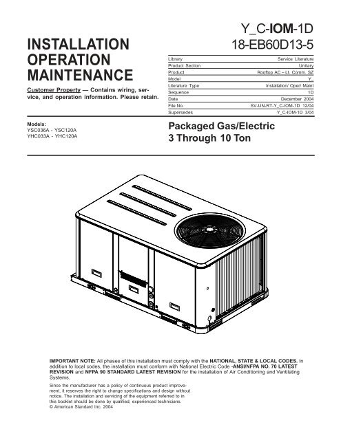
<strong>INSTALLATION</strong><strong>OPERATION</strong><strong>MAINTENANCE</strong>Customer Property — Contains wiring, service,and operation information. Please retain.Models:YSC036A - YSC120AYHC033A - YHC120AY_C-IOM-1D18-EB60D13-5LibraryService LiteratureProduct SectionUnitaryProductRooftop AC – Lt. Comm. SZModelY_Literature TypeInstallation/ Oper/ MaintSequence1DDate December 2004File No. SV-UN-RT-Y_C-IOM-1D 12/04Supersedes Y_C-IOM-1D 3/04Packaged Gas/Electric3 Through 10 TonIMPORTANT NOTE: All phases of this installation must comply with the NATIONAL, STATE & LOCAL CODES. Inaddition to local codes, the installation must conform with National Electric Code -ANSI/NFPA NO. 70 LATESTREVISION and NFPA 90 STANDARD LATEST REVISION for the installation of Air Conditioning and VentilatingSystems.Since the manufacturer has a policy of continuous product improvement,it reserves the right to change specifications and design withoutnotice. The installation and servicing of the equipment referred to inthis booklet should be done by qualified, experienced technicians.© American Standard Inc. 2004
Table of ContentsGeneral InformationLiterature Change History ............. 3Overview of Manual ....................... 3Model Number Description ........... 3Unit Nomenclature ........................ 4Electro Mechanical Control ........... 5Supply Fan Failure Input (Optional) 5Clogged Filter Switch (Optional) ... 6Compressor Disable (CPR1/2) ..... 6ReliaTel Control ............................. 6Electromechanical Control ............ 6High Pressure Control (Optional) .. 6ReliaTel Control ............................. 6Electromechanical Control ............ 6Power Exhaust Control (Optional) . 6Lead/Lag Control ........................... 6(ZSM) (BAYSENS006B) ............... 6(ZSM) (BAYSENS008B) ............... 6(BAYSENS010B) ........................... 6Wall Mounted Relative HumiditySensor (BAYSENS036A) .............. 6Duct Mounted Relative HumiditySensor (BAYSENS037A) ............. 6Programmable Zone Sensor -(BAYSENS019B) ........................... 7Remote Zone Sensor(BAYSENS013B) ........................... 7Remote Zone Sensor(BAYSENS014B) ........................... 7Remote Zone Sensor(BAYSENS016A) ........................... 7Remote Zone Sensor(BAYSENS017B) ........................... 7Electro Mechanical Control ........... 7BAYSENS025A .............................. 7High Temperature Sensor(BAYFRST001A) ............................ 7Evaporator Frost Control ............... 7(ReliaTel Option) ........................ 7(Electro Mechanical Option) .......... 7Pre-Installation ChecklistSmoke Detector Sensor ................ 8Phase Monitor ............................... 8ReliaTel Control Only .................... 8Precautionary Measures ............... 9Unit Clearances..................................................... 10Unit Dimensions..................................................... 11..................................................... 12InstallationRigging andCenter-of-Gravity Data ................ 14Foundation .................................. 15Horizontal Units ........................... 15Downflow Unit Supply &Return Air Openings .................... 15Downflow Unit Supply &Return Air Openings ................... 15Installation ................................... 16Downflow ..................................... 16Factory Installed Economizer ...... 17Temperature Limit SwitchUsage for Gas Heat Units ............ 17IHorizontalDischarge Conversion ................ 18TCO-A Instructions: ...................... 18ITCO-A Instructions: ..................... 19Return Air Smoke Detector .......... 20Through the Base Gas Installation21Requirements for Gas Heat ......... 21Condensate Drain Configuration 22Filter Installation .......................... 22Standard Wiring ........................... 23Optional TBUE Wiring .................. 23Field Installed Control Wiring ...... 23Control Power Transformer .......... 23Controls using 24 VAC ................ 2424V AC Conductors withReliatel ........................................ 2424V AC Conductors withElectromechanical Unit ............... 24Controls using DC AnalogInput/Outputs ............................... 24(Standard Low VoltageMulticonductor Wire) ................... 24(Dehumidification Option) ........... 25Electro Mechanical Control ......... 26Customer Low Voltage Routing- . 26ReliaTel Control .......................... 26Customer Low Voltage Routing- . 26Smoke Detector ........................... 27Customer Low Voltage Wiring- .... 27Space Temperature Averaging .... 28Sizing Natural Gas PipeMains & Branches ....................... 30Pre-startVoltage Imbalance ....................... 31Electrical Phasing ........................ 31Compressor Crankcase Heaters . 31Electro Mechanical Controls ....... 33Electrocmechanical Controls ...... 33Fan Test and Minimum Ventilation 33Economizer Cooling .................... 33(Units with Direct Drive Indoor Fan)33ReliaTel Control ........................... 33(Units with Belt Drive Indoor Fan) 34Start-UpCompressor Start-Up ................... 35Scroll Compressors ..................... 35Dehumidification Option .............. 35Gas Heat Units ............................ 36Final System Setup ...................... 36MaintenanceFan Belt Adjustment -Belt Drive Units ............................ 37Belt Tension Gauge ..................... 37Filters ........................................... 38Return Air Smoke DetectorMaintenance ................................ 38Cooling Season ........................... 38Heating Season ........................... 38Dehumidification Option .............. 40Annual Maintenance ................... 40Final Process ............................... 40Sample Maintenance Log ........... 40Trouble ShootingReliaTel Control ........................... 41System StatusCheckout Procedure ................... 41System Failure ............................. 41Heating Failure ............................ 41Trouble Shooting ......................... 42Cooling Failure ............................ 42Service Failure ............................. 42SimultaneousHeat and Cool Failure ................ 42Cool Failure ................................. 42ResettingCooling and Ignition Lockouts .... 42(ZTS) Service Indicator ................ 42Fan Failure Switch ....................... 43(ZTEMP) ....................................... 43Cooling Set Point (CSP)and Heating Set Point (HSP) ....... 43Relative Humidity Sensor Test .... 43Testing serialcommunication voltage .............. 43ReliaTel RefrigerationModule (RTRM) Default Chart .... 44Unit Economizer Control(ECA) Troubleshooting ................ 44ReliaTel Control ........................... 44Electro Mechanical Control ......... 44Cooling Failure ............................ 45Resetting Cooling andIgnition Lockouts ......................... 45Unit Economizer Control (ECA)Test Procedures ........................... 45Electro Mechanical Control ......... 45Testing the ECAresistors and sensors .................. 452
General InformationUnit NomenclatureDigit 1 - Product TypeY = Packaged Gas/ElectDigit 2 - Unit Efficiency LevelS = StandardH = HighDigit 3 - Airflow ConfigurationC = ConvertibleDigit 4, 5, 6 - Cooling Capacity (MBH)033 = 3 Ton036 = 3 Ton043 = 4 Ton048 = 4 Ton060 = 5 Ton063 = 5 Ton072 = 6 1/4 Ton090 = 7 1/2 Ton (SingleCommpressor)092 = 7 1/2 Ton (Dual Compressor)102 = 8 1/2 Ton120 = 10 TonDigit 7 - Major Design SequenceADigit 8 - Electrical Characteristics1 = 208-230/60/13 = 208-230/60/34 = 460/60/3D = 380-415/50/3K = 380/60/3T = 200/50/3W = 575/60/3Digit 9 - Unit ControlR = Relia TelE = Electro-mechanicalDigit 10 - Heat CapacityH = HighM = MediumL = LowX = Low, Stainless Steel Heat ExchangerY = Medium, Stainless Steel HeatExchangerZ = High, Stainless Steel Heat ExchangerDigit 11 - Minor Design Sequence*Digit 12, 13 - Service Digit Sequence**Digit 14 - Factory Installed Options-Fresh Air Section0 = No Fresh AirA = Manual OA, 0 - 25%B = Motorized OA, 0 - 50%C = Economizer Dry BulbD = Economizer withBarometric ReliefE = Economizer, Reference EnthalpyF = Economizer, Reference Enthalpy,with Barometric ReliefG = Economizer Comparative EnthalpyH = Economizer, Comparative Enthalpy,with Barometric ReliefDigit 15 - Factory Installed Options-Supply Fan0 = Standard Drive1 = Oversize Motor2 = Option Belt DriveDigit 16 - Factory Installed Options-Hinged Service Access0 = Standard Panels/Standard FiltersA = Hinged Access Panels/StandardFiltersB = Standard Panels/2” Pleated FiltersC = Hinged Access Panels/2” PleatedFiltersDigit 17 - Factory Installed Options-Condenser Coil Protection0 = Standard1= Hail Guard2 = Epoxy Coated Condenser Coil3 = Epoxy Coated Condenser CoilandHail GuardDigit 18 - Factory Installed Options-Through The Base0 = Without Through The BaseConnectionA = Through The Base ElectricalConnectionB = Through The Base GasConnectionC = Through The Base Electrical andGas ConnectionDigit 19 - Factory Installed Options-Disconnect Switch/Circuit Breaker0 = Without Disconnect Switch/CircuitBreaker/Phase Monitor1 = Unit Mounted Non-FusedDisconnect Switch2 = Unit Mounted Circuit Breaker3 = Unit Mounted Phase Monitor4 = Unit Mounted Phase Monitor andUnit Mounted Non-FusedDisconnect Switch5 = Unit Mounted Phase Monitor andUnit Mounted Circuit BreakerDigit 20 - Factory Installed Options-Convenience Outlet0 = Without Convenience OutletA = Convenience Outlet UnpoweredB = Convenience Outlet PoweredDigit 21 - Factory Installed Options-Communications0 = Without Communications Options1 = Trane Communications Interface2 = Lontalk Communications Interface3 = Novar Communications InterfaceDigit 22 - Factory Installed Options-Refrigeration System0 = Without Refrigeration System OptionA = Expansion ValveB = Dehumidification OptionDigit 23 - Factory Installed Options-Refrigeration Controls0 = Without Refrigeration Controls1 = High Pressure Control2 = Frostat TM3 = Crankcase Heater4 = High Pressure Control and Frostat5 = High Pressure Control andCrankcase Heater6 = Frostat and Crankcase Heater7 = High Pressure Control, Frostat andCrankcase HeaterDigit 24 - Factory Installed Options-Smoke Detector0 = Without Smoke DetectorA = Return Air Smoke DetectorB = Supply Air Smoke DetectorC = Return and Supply Air SmokeDetectorDigit 25 - Factory Installed Options-System Monitoring Controls0 = Without Monitoring Controls1 = Clogged Filter Switch2 = Fan Failure Switch3 = Discharge Air Sensing Tube4 = Clogged Filter Switch and FanFailure Switch5 = Clogged Filter Switch andDischarge Air Sensing Tube6 = Fan Failure Switch andDischarge Air Sensing Tube7 = Clogged Filter Switch, Fan FailureSwitch andDischarge Air Sensing Tube8 = Novar Return Air Sensor4
General InformationUnit NameplateA Mylar unit nameplate is located on the unit’s corner supportnext to the filter access panel. It includes the unit modelnumber, serial number, electrical characteristics, refrigerantcharge, as well as other pertinent unit data.Compressor NameplateThe nameplate for the compressors are located on the sideof the compressor.Unit DescriptionBefore shipment, each unit is leak tested, dehydrated,charged with refrigerant and compressor oil, and run testedfor proper control operation.The condenser coils are aluminum fin, mechanicallybonded to copper tubing.Direct-drive, vertical discharge condenser fans are providedwith built-in thermal overload protection.There are two control systems offered for these units.The electro mechanical control option uses a thermostat toperform unit functions.The ReliaTel Control Module is a microelectronic controlsystem that is referred to as “Refrigeration Module” (RTRM).The acronym RTRM is used extensively throughout thisdocument when referring to the control system network.These modules through Proportional/Integral control algorithmsperform specific unit functions that governs unit operationin response to; zone temperature, supply air temperature,and/or humidity conditions depending on the application.The stages of capacity control for these units areachieved by starting and stopping the compressors.The RTRM is mounted in the control panel and is factorywired to the respective internal components. The RTRM receivesand interprets information from other unit modules,sensors, remote panels, and customer binary contacts tosatisfy the applicable request for cooling.Economizer Control Actuator (Optional)Electro Mechanical ControlThe ECA monitors the mixed air temperature, ambient drybulb temperature and local minimum position setpoint sensors,if selected, to control dampers to an accuracy of +/- 5%of stroke. The actuator is spring returned to the closed positionany time that power is lost to the unit. It is capable of deliveringup to 25 inch pounds of torque and is powered by24 VAC.ReliaTel ControlThe ECA monitors the mixed air temperature, return air temperature,minimum position setpoint (local or remote),power exhaust setpoint, CO2 setpoint, CO2, and ambientdry bulb/enthalpy sensor or comparative humidity (return airhumidity against ambient humidity) sensors, if selected, tocontrol dampers to an accuracy of +/- 5% of stroke. The actuatoris spring returned to the closed position any time thatpower is lost to the unit. It is capable of delivering up to 25inch pounds of torque and is powered by 24 VAC.RTCI - ReliaTel Trane CommunicationInterface (Optional)This module is used when the application calls for an ICS TMbuilding management type control system. It allows the controland monitoring of the system through an ICS panel. Themodule can be ordered from the factory or ordered as a kitto be field installed. Follow the installation instruction thatships with each kit when field installation is necessary.RLCI - ReliaTel LonTalk CommunicationInterface (Optional)This module is used when the application calls for an ICS TMbuilding management type control system that is LonTalk. Itallows the control and monitoring of the system through anICS panel. The module can be ordered from the factory orordered as a kit to be field installed. Follow the installationinstruction that ships with each kit when field installation isnecessary.RTOM - ReliaTel Options Module (Optional)The RTOM monitors the supply fan proving, clogged filter,supply air temperature, exhaust fan setpoint, supply air tempering,Frostat and smoke detector. Refer to system inputdevices and functions for operation.System Input Devices & FunctionsThe RTRM must have a zone sensor or thermostat input inorder to operate the unit. The flexibility of having severalmode capabilities depends upon the type of zone sensor orthermostat selected to interface with the RTRM.The descriptions of the following basic Input Devices usedwithin the RTRM network are to acquaint the operator withtheir function as they interface with the various modules.Refer to the unit’s electrical schematic for the specific moduleconnections.The following controls are available from the factory for fieldinstallation.Supply Fan Failure Input (Optional)The Fan Failure Switch can be connected to sense indoorfan operation:FFS (Fan Failure Switch) If air flow through the unit is notproven by the differential pressure switch connected to theRTOM (factory set point 0.07 “ w.c.) within 40 seconds nominally,the RTRM will shut off all mechanical operations, lockthe system out, send a diagnostic to ICS, and the SERVICEoutput will flash. The system will remain locked out until areset is initiated either manually or through ICS.5
General InformationClogged Filter Switch (Optional)The unit mounted clogged filter switch monitors the pressuredifferential across the return air filters. It is mounted inthe filter section and is connected to the RTOM. A diagnosticSERVICE signal is sent to the remote panel if the pressuredifferential across the filters is at least 0.5" w.c. The contactswill automatically open when the pressure differentialacross the filters decreases to approximately 0.4" w.c. Theclogged filter output is energized when the supply fan is operatingand the clogged filter switch has been closed for atleast 2 minutes. The system will continue to operate regardlessof the status of the filter switch.Compressor Disable (CPR1/2)This input incorporates the low pressure control (LPC) ofeach refrigeration circuit and can be activated by opening afield supplied contact installed on the LTB.If this circuit is open before the compressor is started, thecompressor will not be allowed to operate. Anytime this circuitis opened for 1 continuous second during compressoroperation, the compressor for that circuit is immediatelyturned “Off”. The compressor will not be allowed to restartfor a minimum of 3 minutes should the contacts close.If four consecutive open conditions occur during the firstthree minutes of operation, the compressor for that circuitwill be locked out, a diagnostic communicated to the remotepanel (if installed), and a manual reset will be required torestart the compressor.Low Pressure ControlReliaTel ControlWhen the LPC is opened for 1 continuous second, the compressorfor that circuit is turned off immediately. The compressorwill not be allowed to restart for a minimum of 3minutes.If four consecutive open conditions occur during the firstthree minutes of operation, the compressor will be lockedout, a diagnostic communicated to ICS TM if applicable, and amanual reset will be required to restart the compressor.Electromechanical ControlWhen the LPC is opened, the compressor for that circuit isturned off immediately. The compressor will restart when theLPC closes.High Pressure Control (Optional)ReliaTel ControlThe high pressure controls are wired in series between thecompressor outputs on the RTRM and the compressorcontactor coils. If the high pressure control switch opens, theRTRM senses a lack of current while calling for cooling andlocks the compressor out.On dual circuit units, if the high pressure control opens, thecompressor on the affected circuit is locked out. A manualreset for the affected circuit is required.Electromechanical ControlWhen the HPC is opened, the compressor for that circuit isturned off immediately. The compressor will restart when theHPC closes.Power Exhaust Control (Optional)ReliaTel ControlThe power exhaust fan is started whenever the position ofthe economizer dampers meets or exceed the power exhaustsetpoint when the indoor fan is on.With the optional ventilation override accessory, the powerexhaust fan is independent of the indoor fan.The setpoint panel is located in the return air section and isfactory set at 25%.Electromechanical ControlThe power exhaust fan is started whenever the indoor fan ison and the adjustable damper limit switch DLS is closed.Lead/Lag Control (Dual Circuit Only)ReliaTel Control OnlyLead/Lag is a selectable input located on the RTRM. TheRTRM is configured from the factory with the Lead/Lagcontrol disabled. To activate the Lead/Lag function, simplycut the wire connected to J3-8 at the RTRM. When it isactivated, each time the designated lead compressor is shutoff due to the load being satisfied, the lead compressor orrefrigeration circuit switches. When the RTRM is poweredup, i.e. after a power failure, the control will default to thenumber one circuit compressor.Zone Sensor Module (ZSM) (BAYSENS006B)This electronic sensor features three system switch settings(Heat, Cool, and Off) and two fan settings (Onand Auto). It is a manual changeover control with singlesetpoint. (Cooling Setpoint Only)Zone Sensor Module (ZSM) (BAYSENS008B)This electronic sensor features four system switch settings(Heat, Cool, Auto, and Off) and two fan settings (On andAuto). It is a manual or auto changeover control with dualsetpoint capability. It can be used with a remote zone temperaturesensor BAYSENS017B.Zone Sensor (BAYSENS010B)This electronic sensor features four system switch settings(Heat, Cool, Auto, and Off) and two fan settings (On andAuto) with four system status LED’s. It is a manual or autochangeover control with dual setpoint capability. It can beused with a remote zone temperature sensorBAYSENS017B.Wall Mounted Relative Humidity Sensor (BAYSENS036A)Field installed, wall mounted humidity sensor is used tocontrol activation of the hot gas reheat dehumidificationoption. Humidity set points can be selected for relativehumidity levels between 40% and 60% by adjusting theDEHUMID setting on the ReliaTel Options Module. Seepage 24.Duct Mounted Relative Humidity Sensor(BAYSENS037A)Field installed, duct mounted humidity sensor is used tocontrol activation of the hot gas reheat dehumidificationoption. Humidity set points can be selected for relativehumidity levels between 40% and 60% by adjusting theDEHUMID setting on the ReliaTel Options Module. Seepage 24.6
General InformationProgrammable Zone Sensor - (BAYSENS019B)This 7 day programmable sensor features 2, 3 or 4 periodsfor Occupied or Unoccupied programming per day. If thepower is interrupted, the program is retained in permanentmemory. If power is off for an extended period of time, onlythe clock and day may have to be reset.The Zone Sensor allows selection of 2, 3 or 4 system modes(Heat, Cool, Auto, and Off), two fan modes (On and Auto). Ithas dual temperature selection with programmable start timecapability.The occupied cooling set point ranges between 45 and 98degrees Fahrenheit. The heating set point ranges between43 and 96 degrees Fahrenheit.A liquid crystal display (LCD) displays zone temperature,temperature set points, day of the week, time, and operationalmode symbols.The Option Menu is used to enable or disable applicablefunctions, i.e.; Morning Warm-up, Economizer minimum positionoverride during unoccupied status, Fahrenheit or Centigrade,Supply air tempering, Remote zone temperature sensor,12/24 hour time display, Smart fan, and Computed recovery.During an occupied period, an auxiliary relay rated for 1.25amps @ 30 volts AC with one set of single pole double throwcontacts is activated.Status Inputs (4 Wires Optional)The ZSM can be wired to receive four (4) operating statussignals from the RTRM (HEAT, COOL, SYSTEM “ON”, SER-VICE).Four (4) wires from the RTRM should be connected tothe appropriate terminals (7, 8, 9 & 10) on the ZSM.Remote Zone Sensor (BAYSENS013B)This electronic sensor features remote zone sensing andtimed override with override cancellation. It is used with aTrane Integrated Comfort TM building management system.Remote Zone Sensor (BAYSENS014B)This electronic sensor features single setpoint capability andtimed override with override cancellation. It is used with aTrane Integrated Comfort TM building management system.Remote Zone Sensor (BAYSENS016A)This bullet type temperature sensor can be used for; outsideair (ambient) sensing, return air temperature sensing, supplyair temperature sensing, remote temperature sensing (uncovered.Wiring procedures vary according to the particularapplication and equipment involved. Refer to the unit’s wiringdiagrams for proper connections.BAYSTAT036ASingle Stage - 1 Heat/1 CoolBAYSTAT037AMulti Stage - 2 Heat/2 Cool - Can be Used for EconomizerOperationBAYSENS025ARemote sensor for BAYSTAT036A and BAYSTAT037AHigh Temperature Sensor (BAYFRST001A)This sensor connects to the RTRM Emergency Stop Inputon the LTB and provides high limit “shutdown” of the unit.The sensor is used to detect high temperatures due to firein the air conditioning or ventilation ducts. The sensor isdesigned to mount directly to the sheet metal duct. Each kitcontains two sensors. The return air duct sensor(X1310004001) is set to open at 135 F. The supply air ductsensor (X1310004002) is set to open at 240 F. The controlcan be reset after the temperature has been lowered approximately25 F below the cutout setpoint.Evaporator Frost Control(ReliaTel Option)This input incorporates the Frostat control (FOS)mounted in the indoor coil circuit and can be activated byclosing a field supplied contact installed in parallel withthe FOS.If this circuit is open before the compressor is started, thecompressor will not be allowed to operate. Anytime thiscircuit is opened for 1 continuous second during compressoroperation, the compressor for that circuit is immediatelyturned “Off”. The compressor will not be allowed torestart for a minimum of 3 minutes should the FOS close.(Electro Mechanical Option)This input incorporates the Frostat control (FOS)mounted in the indoor coil circuit and can be activated byopening a field supplied contact installed in series with theFOS.If this circuit is open before the compressor is started, thecompressor will not be allowed to operate. Anytime thiscircuit is opened during compressor operation, the compressorfor that circuit is immediately turned “Off”. Thecompressor will restart when the FOS closes.Remote Zone Sensor (BAYSENS017B)This electronic sensor can be used with BAYSENS006B,008B, 010B, 019B Remote Panels. When this sensor is wiredto a BAYSENS019B Remote Panel, wiring must be 18 AWGShielded Twisted Pair (Belden 8760 or equivalent). Refer toThe specific Remote Panel for wiring details.Electro Mechanical ControlThe unit must have a Thermostat to operate.7
Pre-Installation ChecklistSmoke Detector Sensor (Optional)This sensor is only applicable on units equipped with aRTOM. It provides high limit “shutdown” of the unit and requiresa manual reset. The sensor is used to detect smokedue to fire in the air conditioning or ventilation ducts.Important: The supply and return air smokedetectors are designed to shut off the unit if smokeis sensed in the supply air stream or return airstream. This function is performed by sampling theairflow entering the unit at the return air opening.Follow the instructions provided below to assure thatthe airflow through the unit is sufficient for adequatesampling. Failure to follow these instructions willprevent the smoke detectors from performing it'sdesign function.Phase Monitor (Optional)ReliaTel Control OnlyThis sensor monitors voltage between the 3 conductors ofthe 3 phase power supply. Two LED lights are provided. Thegreen light indicates that a balanced 3 phase supply circuitis properly connected. The red light indicates that unit operationhas been prevented. There are two conditions thatwill prevent unit operation.The power supply circuit is notbalanced with the proper phase sequence of L1,L2,L3 forthe 3 conductors of a 3 phase circuit. The line to line voltageis not between 180 volts and 633 volts.Important: Airflow through the unit is affected by theamount of dirt and debris accumulated on the indoorcoil and filters. To insure that airflow through the unitis adequate for proper sampling by the return airsmoke detector, complete adherence to themaintenance procedures, including recommendedintervals between filter changes, and coil cleaning isrequired.Important: Periodic checks and maintenanceprocedures must be performed on the smokedetector to insure that it will function properly. Fordetailed instructions concerning these checks andprocedures, refer to the appropriate section(s) of thesmoke detector Installation and MaintenanceInstructions provided with the literature package forthis unit.In order for the supply air smoke detector or return airsmoke detector to properly sense smoke in the supply airstream or return air stream, the air velocity entering thesmoke detector unit must be between 500 and 4000 feetper minute. Equipment covered in this manual will developan airflow velocity that falls within these limits over the entireairflow range specified in the evaporator fan performancetables.There are certain models, however, if operated at low airflow,will not develop an airflow velocity that falls within therequired 500 to 4000 feet per minute range. For these models,the design airflow shall be greater than or equal to1000 feet per minute MINIMUM.8
Unit InspectionAs soon as the unit arrives at the job site[ ] Verify that the nameplate data matches the data on thesales order and bill of lading (including electrical data).[ ] Verify that the power supply complies with the unit nameplatespecifications.[ ] Visually inspect the exterior of the unit, including the roof,for signs of shipping damage.WARNINGFiberglass Wool !Product contains fiberglass wool. Disturbing the insulationin this product during installation, maintenance orrepair will expose you to airborne particles of glass woolfibers and ceramic fibers known to the state of Californiato cause cancer through inhalation. Glass wool fibersmay also cause respiratory, skin or eye irritation.Precautionary Measures· Avoid breathing fiberglass dust.· Use a NIOSH approved dust/mist respirator.Request an immediate joint inspection of the damage bythe carrier and the consignee. Do not remove damagedmaterial from the receiving location. Take photos of thedamage, if possible. The owner must provide reasonableevidence that the damage did not occur after delivery.[ ] Notify the appropriate sales representative before installingor repairing a damaged unit.StorageTake precautions to prevent condensate from forming insidethe unit’s electrical compartments and motors if:a. the unit is stored before it is installed; or,b. the unit is set on the roof curb, and temporary heat is providedin the building. Isolate all side panel service entrancesand base pan openings (e.g., conduit holes, S/Aand R/A openings, and flue openings) from the ambientair until the unit is ready for start-up.Note: Do not use the unit’s heater for temporary heatwithout first completing the start-up proceduredetailed under “Starting the Unit”.The manufacturer will not assume any responsibility forequipment damage resulting from condensate accumulationon the unit’s electrical and/or mechanical components.· Avoid contact with the skin or eyes. Wear longsleeved,loose-fitting clothing, gloves, and eye protection.· Wash clothes separately from other clothing: rinsewasher thoroughly.· Operations such as sawing, blowing, tear-out,and spraying may generate fiber concentrationsrequiring additional respiratory protection. Usethe appropriate NIOSH approved respiration inthese situations.First Aid MeasuresEye Contact - Flush eyes with water to remove dust. Ifsymptoms persist, seek medical attention.Skin Contact - Wash affected areas gently with soap andwarm water after handling.If the job site inspection of the unit reveals damage or materialshortages, file a claim with the carrier immediately.Specify the type and extent of the damage on the “bill of lading”before signing.[ ] Visually inspect the internal components for shippingdamage as soon as possible after delivery and before itis stored. Do not walk on the sheet metal base pans.[ ] If concealed damage is discovered, notify the carrier’s terminalof damage immediately by phone and by mail.Concealed damage must be reported within 15 days.9
Unit ClearancesFigure 1 illustrates the minimum operating and serviceclearances for either a single or multiple unit installation.These clearances are the minimum distances necessary toassure adequate serviceability, cataloged unit capacity, andpeak operating efficiency.Providing less than the recommended clearances may resultin condenser coil starvation, “short-circuiting” of exhaustand economizer airflows, or recirculation of hot condenserair.Figure 1Typical Installation Clearances for Single & Multiple UnitApplicationsUnit Clearances10
Unit DimensionsFigure 2Unit Dimensional DataYHC033A, Y(H/S)C036A, YHC043A, Y(H/S)C048A — Low and Medium HeatYSC060A — Low and Medium HeatUnit Dimensional DataYHC033A, Y(H/S)C036A, YHC043A,Y(H/S)C048A — High HeatYSC060A — High HeatYHC060A, YHC063A — Low, Medium, and High Heat11
Figure 2 - ContinuedUnit Dimensional DataY(H/S)C072A, YSC090A, YSC092AUnit DimensionsUnit Dimensional DataYHC092A, Y(H/S)102A, Y(H/S)C120A12
InstallationTable 1Typical Unit Weights & Point Loading DataNetCenterNetCenterUnit Weight Corner Wt. (lbs) of Gravity (In.)Unit Weight Corner Wt. (kg) of Gravity (mm.)Model (lbs) A B C D Length Width Model (kg) A B C D Length WidthYSC036A1*(L,M,X,Y) 453 143 116 90 104 32 19 YSC036A1*(L,M,X,Y) 205 65 53 41 47 811 478YSC036A1*(H,Z) 480 151 124 96 109 32 19 YSC036A1*(H,Z) 218 68 56 44 50 815 478YSC036A(3,4,W)*(L,M,X,Y) 453 143 116 90 104 32 19 YSC036A(3,4,W)*(L,M,X,Y) 205 65 53 41 47 811 478YSC036A(3,4,W)*(H,Z) 480 151 124 96 109 32 19 YSC036A(3,4,W)*(H,Z) 218 68 56 44 50 815 478YSC048A1*(L,M,X,Y) 478 151 122 102 103 33 19 YSC048A1*(L,M,X,Y) 217 68 55 46 47 833 479YSC048A1*(H,Z) 505 159 130 108 109 33 19 YSC048A1*(H,Z) 229 72 59 49 49 835 479YSC048A(3,4,W)*(L,M,X,Y) 465 146 121 101 97 33 19 YSC048A(3,4,W)*(L,M,X,Y) 211 66 55 46 44 848 475YSC048A(3,4,W)*(H,Z) 492 154 129 107 103 33 19 YSC048A(3,4,W)*(H,Z) 223 70 58 48 47 850 475YSC060A1*(L,M,X,Y) 494 160 127 99 108 32 18 YSC060A1*(L,M,X,Y) 224 73 57 45 49 812 469YSC060A1*(H,Z) 522 169 134 105 114 32 18 YSC060A1*(H,Z) 237 76 61 48 52 816 469YSC060A(3,4,K,W)*(L,M,X,Y) 494 160 127 99 108 32 18 YSC060A(3,4,K,W)*(L,M,X,Y) 224 73 57 45 49 812 469YSC060A(3,4,K,W)*(H,Z) 522 169 134 105 114 32 18 YSC060A(3,4,K,W)*(H,Z) 237 76 61 48 52 816 469YSC072A(3,4,K,W)*(L,X) 720 245 188 129 158 39 21 YSC072A(3,4,K,W)*(L,X) 326 111 85 58 71 992 535YSC072A(3,4,W)*(M,Y) 731 248 192 131 160 39 21 YSC072A(3,4,W)*(M,Y) 332 113 87 60 72 996 536YSC072A(3,4,K,W)*(H,Z) 735 249 193 132 161 39 21 YSC072A(3,4,K,W)*(H,Z) 334 113 88 60 73 998 536YSC090A(3,4,K,W)*(L,X) 804 269 203 142 190 38 22 YSC090A(3,4,K,W)*(L,X) 365 122 92 64 86 967 555YSC090A(3,4,W)*(M,Y) 808 270 204 143 191 38 22 YSC090A(3,4,W)*(M,Y) 367 123 93 65 86 968 556YSC090A(3,4,K,W)*(H,Z) 820 273 208 146 193 38 22 YSC090A(3,4,K,W)*(H,Z) 372 124 94 66 87 972 556YSC092A(3,4,W)*(L,X) 806 273 217 143 172 40 21 YSC092A(3,4,W)*(L,X) 366 124 99 65 78 1008 526YSC092A(3,4,W)*(M,Y) 810 274 219 144 173 40 21 YSC092A(3,4,W)*(M,Y) 367 124 99 65 78 1009 527YSC092A(3,4,W)*(H,Z) 822 277 222 147 175 40 21 YSC092A(3,4,W)*(H,Z) 373 126 101 67 79 1013 527YSC102A(3,4,K,W)*(L,X) 883 293 238 161 191 40 21 YSC102A(3,4,K,W)*(L,X) 400 133 108 73 87 1017 537YSC102A(3,4,W)*(M,Y) 887 294 239 162 192 40 21 YSC102A(3,4,W)*(M,Y) 402 133 108 73 87 1018 537YSC102A(3,4,K,W)*(H,Z) 899 297 243 165 194 40 21 YSC102A(3,4,K,W)*(H,Z) 408 135 110 75 88 1021 538YSC120A(3,4,K,W)*(L,X) 933 310 253 171 198 40 21 YSC120A(3,4,K,W)*(L,X) 423 141 115 78 90 1018 540YSC120A(3,4,W)*(M,Y) 945 313 257 174 200 40 21 YSC120A(3,4,W)*(M,Y) 429 142 117 79 91 1021 540YSC120A(3,4,K,W)*(H,Z) 958 317 261 177 202 40 21 YSC120A(3,4,K,W)*(H,Z) 434 144 118 80 92 1024 541YHC036A1*(L,M,X,Y) 470 150 120 95 105 32 19 YHC036A1*(L,M,X,Y) 213 68 55 43 47 816 475YHC036A1*(H,Z) 497 158 128 101 110 32 19 YHC036A1*(H,Z) 226 72 58 46 50 819 475YHC033A(3,4,W)*(L,M,X,Y) 537 159 139 126 111 32 19 YHC033A(3,4,W)*(L,M,X,Y) 244 72 63 57 50 816 475YHC036A(3,4,W)*(L,M,X,Y) 470 150 120 95 105 32 19 YHC036A(3,4,W)*(L,M,X,Y) 213 68 55 43 47 816 475YHC033A(3,4,W)*(H,Z) 537 159 139 126 111 32 19 YHC033A(3,4,W)*(H,Z) 244 72 63 57 50 819 475YHC036A(3,4,W)*(H,Z) 497 158 128 101 110 32 19 YHC036A(3,4,W)*(H,Z) 226 72 58 46 50 819 475YHC048A1*(M,Y) 511 157 126 108 121 32 20 YHC048A1*(M,Y) 232 71 57 49 55 812 499YHC048A1*(H,Z) 539 166 133 114 126 32 20 YHC048A1*(H,Z) 244 75 61 52 57 815 497YHC043A(3,4,W)*(L,M,X,Y) 577 167 144 139 127 32 20 YHC043A(3,4,W)*(L,M,X,Y) 262 76 65 63 58 812 499YHC048A(3,4,W)*(L,M,X,Y) 511 157 126 108 121 32 20 YHC048A(3,4,W)*(L,M,X,Y) 232 71 57 49 55 812 499YHC043A(3,4,W)*(H,Z) 577 167 144 139 127 32 20 YHC043A(3,4,W)*(H,Z) 262 76 65 63 58 815 497YHC048A(3,4,W)*(H,Z) 539 166 133 114 126 32 20 YHC048A(3,4,W)*(H,Z) 244 75 61 52 57 815 497YHC060A1*(L,M) 562 176 137 116 133 31 20 YHC060A1*(L,M) 255 80 62 53 60 800 495YHC060A1*(H,Z) 574 179 140 119 136 32 20 YHC060A1*(H,Z) 260 81 64 54 62 803 496YHC060A(3,4,W)*(L,M,X,Y) 550 175 133 110 131 31 19 YHC060A(3,4,W)*(L,M,X,Y) 249 79 60 50 60 788 491YHC063A(3,4,W)*(L,M,X,Y) 612 180 151 144 137 31 19 YHC063A(3,4,W)*(L,M,X,Y) 278 82 68 65 62 788 491YHC060A(3,4,W)*(H,Z) 561 178 137 113 134 31 19 YHC060A(3,4,W)*(H,Z) 255 81 62 51 61 792 492YHC063A(3,4,W)*(H,Z) 561 178 137 113 134 31 19 YHC063A(3,4,W)*(H,Z) 255 81 62 51 61 792 492YHC072A(3,4,W)*(L,X) 756 245 193 137 181 39 22 YHC072A(3,4,W)*(L,X) 343 111 88 62 82 985 567YHC072A(3,4,W)*(M,Y) 768 248 197 140 183 39 22 YHC072A(3,4,W)*(M,Y) 348 112 89 64 83 989 567YHC072A(3,4,W)*(H,Z) 772 249 198 141 184 39 22 YHC072A(3,4,W)*(H,Z) 350 113 90 64 84 990 567YHC092A(3,4,W)*(L,X) 907 302 238 161 207 39 22 YHC092A(3,4,W)*(L,X) 411 137 108 73 94 990 546YHC092A(3,4,W)*(M,Y) 911 303 239 162 208 39 22 YHC092A(3,4,W)*(M,Y) 413 137 108 73 94 991 546YHC092A(3,4,W)*(H,Z) 923 306 243 165 210 39 22 YHC092A(3,4,W)*(H,Z) 419 139 110 75 95 994 547YHC102A(3,4,W)*(L,X) 942 306 247 171 217 39 22 YHC102A(3,4,W)*(L,X) 427 139 112 78 98 1001 555YHC102A(3,4,W)*(M,Y) 946 307 248 172 218 39 22 YHC102A(3,4,W)*(M,Y) 429 139 113 78 99 1002 555YHC102A(3,4,W)*(H,Z) 957 310 252 175 220 40 22 YHC102A(3,4,W)*(H,Z) 434 141 114 79 100 1005 555YHC120A(3,4,W)*(L,X) 1035 336 269 191 240 39 22 YHC120A(3,4,W)*(L,X) 469 152 122 87 109 1000 560YHC120A(3,4,W)*(M,Y) 1047 339 272 194 242 39 22 YHC120A(3,4,W)*(M,Y) 475 154 123 88 110 1003 560YHC120A(3,4,W)*(H,Z) 1060 342 277 197 245 40 22 YHC120A(3,4,W)*(H,Z) 481 155 125 89 111 1006 56013
Typical Accessory WeightsInstallationOption / AccessoryDescriptionWeight - Net lbsYHC033, 043, 063 YH/YS036-060 YH/YS072-120Economizer 26 26 36Motorized Damper 20 20 30Manual Damper 16 16 26Barometric Relief 7 7 10Power Exhaust N/A N/A 80Oversize Motor 5 5 8Belt Drive Motor (3 phase only) Standard 31 StandardHinged Access 10 10 12Hail Guard 12 12 20Through the Base: Electrical 8 8 13Through the Base : Gas 5 5 5Unit Disconnect Switch 5 5 5Unit Circuit Breaker 5 5 5Conv. Outlet: Unpowered 2 2 2Conv. Outlet: Powered 38 38 38TCI, LCI 1 1 1NOVAR 8 8 8HPC 1 1 1Frostat 1 1 1Crankcase Heater 1 1 1Smoke Detector, Return 7 7 7Smoke Detector, Supply 5 5 5Clogged Filter Switch 1 1 1Fan Fail Switch 1 1 1Discharge Air Tube 3 3 3Roofcurb 70 70 115LP Conversion Kit 3 3 3All Zone Sensors 3 3 1Hard Start Kit 3 3 N/AReheat Coil 15 15 25Stainless Steel Heat Exchanger 5 5 10Figure 3Rigging and Center-of-Gravity DataWARNINGHeavy Objects!Do not use cables (chains or slings) except as shown.Each of the cables (chains or slings) used to lift the unitmust be capable of supporting the entire weight of theunit. Lifting cables (chains or slings) may not be of thesame length. Adjust as necessary for even unit lift. Otherlifting arrangements may cause equipment or propertyonlydamage. Failure to properly lift unit may result indeath or serious injury.WARNINGImproper Unit Lift!Test lift unit approximately 24 inches to verify propercenter of gravity lift point. To avoid dropping of unit, repositionlifting point if unit is not level. Failure to properly liftunit could result in death or serious injury or possibleequipment or property-only damage.14
FoundationInstallationDuctworkHorizontal UnitsIf the unit is installed at ground level, elevate it above thesnow line. Provide concrete footings at each support locationwith a “full perimeter” support structure or a slab foundationfor support. Refer to Table 1 for the unit’s operatingand point loading weights when constructing a footing foundation.If anchoring is required, anchor the unit to the slab usinghold down bolts or isolators. Isolators should be installed tominimize the transmission of vibrations into the building.For rooftop applications, ensure the roof is strong enough tosupport the combined unit and support structural weight.Refer to Table 1 for the unit operating weights. If anchoringis required, anchor the unit to the roof with hold-down boltsor isolators.Figure 4-1 illustrates the supply and return air openings asviewed from the rear of the unit.Elbows with turning vanes or splitters are recommended tominimize air noise due to turbulence and to reduce staticpressure.When attaching the ductwork to the unit, provide a watertight flexible connector at the unit to prevent operatingsounds from transmitting through the ductwork.All outdoor ductwork between the unit and the structureshould be weather proofed after installation is completed.Check with a roofing contractor for proper waterproofingprocedures.Figure 4-13 through 5 TonHorizontal Unit Supply & Return Air OpeningFigure 4-13 through 5 TonDownflow Unit Supply & Return Air Openings6 1/4 through 10 TonHorizontal Unit Supply & Return Air Opening6 1/4 through 10 TonDownflow Unit Supply & Return Air Openings15
Roof CurbInstallationDownflowThe roof curbs for these units consists of a “full perimeter”enclosure to support the unit.b. For “built-up” curbs supplied by others, gaskets mustbe installed around the curb perimeter flange and thesupply and return air opening flanges.RiggingBefore installing any roof curb, verify;1. That it is the correct curb for the unit,2. That it includes the necessary gaskets and hardware,3. That the purposed installation location provides the requiredclearance for proper operation.4. Insure that the curb is level and square. The top surface ofthe curb must be true to assure an adequate curb-to-unitseal.WARNINGCombustible Materials!Maintain proper clearance between the unit heat exchanger,vent surfaces and combustible materials. Referto unit nameplate and installation instructions for properclearances. Improper clearances could result in a firehazard. Failure to maintain proper clearances could resultin death or serious injury or property damage.5. Verify that appropriate materials were used in the constructionof roof and ductwork. Combustible materialsshould not be used in the construction of ductwork or roofcurb that is in close proximity to heater elements or anyhot surface. Any combustible material on the inside of theunit base should be removed and replaced with appropriatematerial.Step-by-step curb assembly and installation instructionsship with each accessory roof curb kit. Follow the instructionscarefully to assure proper fit-up when the unit is setinto place.Note: To assure proper condensate flow duringoperation, the unit (and curb) must be level.If the unit is elevated, a field constructed catwalk around theunit is strongly recommended to provide easy access forunit maintenance and service.A Rigging illustration and Center-of-Gravity dimensionaldata table is shown in Figure 3. Refer to the typical unit operatingweights table before proceeding.1. Remove all drill screws fastening wood protection tometal baserail. Remove all screws securing wooden protectionto wooden top crate.2. Remove Wooden Top Crate.WARNINGHeavy Objects!Do not use cables (chains or slings) except as shown.Each of the cables (chains or slings) used to lift the unitmust be capable of supporting the entire weight of theunit. Lifting cables (chains or slings) may not be of thesame length. Adjust as necessary for even unit lift. Otherlifting arrangements may cause equipment or propertyonlydamage. Failure to properly lift unit may result indeath or serious injury. See details below.3. Rig the unit as shown in Figure 3. Attach adequatestrength lifting slings to all four lifting brackets in the unitbase rail. Do not use cables, chains, or slings except asshown.4. Install a lifting bar, as shown in Figure 3, to protect the unitand to facilitate a uniform lift. The minimum distance betweenthe lifting hook and the top of the unit should be 7feet.5. Test-lift the unit to ensure it is properly rigged and balanced,make any necessary rigging adjustments.6. Lift the unit enough to allow the removal of two Fork Liftbrackets and hardware. Remove the two Fork Lift brackets,two metal runners and three wooden boards asshown in the following Figure.Recommendations for installing the Supply Air and ReturnAir ductwork joining the roof curb are included in the curbinstruction booklet. Curb ductwork must be fabricated andinstalled by the installing contractor before the unit is setinto place.Note: For sound consideration, cut only the holes inthe roof deck for the ductwork penetrations. Do notcut out the entire roof deck within the curb perimeter.If a Curb Accessory Kit is not used:a. The ductwork can be attached directly to the factoryprovidedflanges around the unit’s supply and returnair openings. Be sure to use flexible duct connectionsat the unit.7. Downflow units; align the base rail of the unit with thecurb rail while lowering the unit onto the curb. Make surethat the gasket on the curb is not damaged while positioningthe unit.16
InstallationGeneral Unit RequirementsThe checklist listed below is a summary of the steps requiredto successfully install a commercial unit. This checklistis intended to acquaint the installing personnel withwhat is required in the installation process. It does not replacethe detailed instructions called out in the applicablesections of this manual.[ ] Check the unit for shipping damage and material shortage;file a freight claim and notify appropriate sales representative.[ ] Verfiy correct model, options and voltage from unit nameplate.[ ] Verify that the installation location of the unit will providethe required clearance for proper operation.[ ] Assemble and install the roof curb (if applicable). Refer tothe latest edition of the curb installers guide that shipswith each curb kit.[ ] Fabricate and install ductwork; secure ductwork to curb.[ ] Install pitch pocket for power supply through building roof.(If applicable)[ ] Rigging the unit.[ ] Set the unit onto the curb; check for levelness.[ ] Ensure unit-to-curb seal is tight and without buckles orcracks.[ ] Install and connect a condensate drain line to the evaporatordrain connection.Factory Installed Economizer[ ] Ensure the economizer has been pulled out into the operatingposition. Refer to the economizer installers guidefor proper position and setup.[ ] Install all access panels.Temperature Limit Switch Usage for Gas Heat UnitsUnits are factory shipped in the downflow dischargeconfriguration but can be field converted to a horizontal dischargeconfriguration. Some, but not all units require a differentTC01 limit switch, which is attached to the combustionblower motor if horizontal discharge confriguration is used.Note: The following units require a limit switchchange out for horizontal discharge. The additionallimit switch is shipped attached to the blowerhousing. Proceed to the Horizontal DischargeConversion, Step 5 on page 18 for the followingmodels "ONLY". Y*C036A**(H,Z) , Y*C048A**(H,Z),Y*C060A**(H,Z), YHC060A**(M,Y), Y*C072A**(H,Z),YSC090A**(M,Y), Y*C092A**(M,Y), YHC092A**(H,Z),Y*C102A**(M,Y), Y*C102A**(H,Z), Y*C120A**(M,Y),Y*C120A**(H,Z).If any of the above units are installed in the downflow dischargeconfiguration, remove the additional TC01 limitswitch from the combustion blower motor and discard.Unit ModelTCO1 Tripping ValuesDownflow / HorizontalYHC033A**(L,X)170FYHC033A**(M,Y) 220FYHC033A**(H,Z) 190F / 210FY*C036A**(L,X)170FY*C036A**(M,Y)220FY*C036A**(H,Z) 190F / 210FYHC043A**(L,X)170FYHC043A**(M,Y) 170FYHC043A**(H,Z) 180F /220FY*C048A**(L,X)170FY*C048A**(M,Y)170FY*C048A**(H,Z) 180F /220FYHC060A**(L,X)155FYHC060A**(M,Y) 155F / 170FYHC060A**(H,Z) 170F / 200FYHC063A**(L,X)155FYHC063A**(M,Y) 155F / 170FYHC063A**(H,Z) 170F / 200FYSC060A**(L,X)170FYSC060A**(M,Y) 170FYSC060A**(H,Z) 170F / 200FY*C072A**(L,X)200FY*C072A**(M,Y)200FY*C072A**(H,Z) 180F / 210FYSC090A**(L,X)200FYSC090A**(M,Y) 180F / 220FYSC090A**(H,Z)200FYHC092A**(L,X)225FYHC092A**(M,Y) 180F / 220FYHC092A**(H,Z) 180F /220FYSC092A**(L,X)200FYSC092A**(M,Y) 180F / 220FYSC092A**(H,Z)200FY*C102A**(L,X)225FY*C102A**(M,Y) 180F / 220FY*C102A**(H,Z) 190F / 260FY*C120A**(L,X)200FY*C120A**(M,Y) 190F / 260FY*C120A**(H,Z) 190F / 260F17
InstallationHorizontal Discharge Conversion3 Through 5 Ton UnitsIf a unit is to be converted to Horizontal discharge, the followingconversion must be preformed:1. Remove the return and supply duct covers.2. Apply white gasket to the supply duct cover as shown.White gasket is located in the Ship With bag located inthe control box.TCO-A Instructions:If the unit being installed is listed in the following table thelimit control TCO1 must be replaced with the extra limit controlshipped in the heater compartment. Replace TCO1 followingthe instructions in steps 1through 3 below. If the unitbeing installed does not correspond to any in the followingtable, skip steps1 through 3 and go on to next step in the installationprocess.Unit Model NumberYHC033A**(H,Z), YHC043A**(H,Z),YHC063A**(M,Y), YHC063A**(H,Z),Y*C036A**(H,Z), Y*C048A**(H,Z),Y*C060A**(H,Z), YHC060A**(M,Y)3. Position duct covers as shown below. Rotate supply ductcover 90 degrees to allow it to be slid into supply opening.Note: If unit is equipped with Return Air SmokeDetector refer to field conversion for horizontaldischarge before installing return air duct cover.4. Slide duct covers into duct openings until endward edgeof the duct cover engages with the 2 retaining clips onthe duct flanges. Secure the outward edge of the eachduct cover with 2 screws.WARNINGHazardous Voltage!Disconnect all electric power, including remote disconnectsbefore servicing. Follow proper lockout/tagout proceduresto ensure the power can not be inadvertentlyenergized. Failure to disconnect power before servicingcould result in death or serious injury.1. Remove the heat section access panel.2. Remove TC01 from shipping location, attached to thecombustion blower.Note: The following units require a limit switchchange out. The additional limit switch is shippedattached to the blower housing for thesemodels.Proceed to Step 5 for the following models"ONLY".YHC033A**(H,Z) , YHC043A**(H,Z) , YHC063A**(H,Z), Y*C036A**(H,Z) , Y*C048A**(H,Z) , Y*C060A**(H,Z) ,YHC060A**(M,Y)3. Replace and discard the existing TC01 originally installedat the factory for downflow operation with theTC01 shipped attached to the combustion blower forhorizontal operation.4. Replace heat section access panel.5. After completing installation of the duct covers for horizontaldischarge, proceed to TCO-A instructions.18
Horizontal Discharge Conversion6 Through 10 Ton UnitsIf a unit is to be converted to Horizontal discharge, the followingconversion must be preformed:1. Remove the return and supply duct covers.Installation2. Apply white gasket to the supply duct cover as shown.White gasket is located in the Ship With bag located inthe control box.TCO-A Instructions:If the unit being installed is listed in the following table thelimit control TCO1 must be replaced with the extra limit controlshipped in the heater compartment. Replace TCO1 followingthe instructions in steps 1through 3 below. If the unitbeing installed does not correspond to any in the followingtable, skip steps1 through 3 and go on to next step in the installationprocess.Unit Model NumberY*C072A**(H,Z), YSC090A**(M,Y),Y*C092A**(M,Y), YHC092A**(H,Z),Y*C102A**(M,Y), Y*C102A**(H,Z),Y*C120A**(M,Y), Y*C120A**(H,Z)WARNINGHazardous Voltage!3. Position duct covers as shown below. The supply ductcover is installed ( insulation side down )over thedownflow return opening by engaging one side of thepanel under a retaining angle and securing the otherside with 3 screws.Note: If unit is equipped with Return Air SmokeDetector refer to field conversion for horizontaldischarge before installing return air duct cover.4. Slide return duct cover ( insulation side up ) into supplyopenings until endward edge of the duct cover engageswith the 2 retaining clips on the duct flanges. Secure theoutward edge of the each duct cover with 2 screws.Disconnect all electric power, including remote disconnectsbefore servicing. Follow proper lockout/tagout proceduresto ensure the power can not be inadvertently energized.Failure to disconnect power before servicingcould result in death or serious injury.1. Remove the heat section access panel.2. Remove TC01 from shipping location, attached to thecombustion blower.3. Replace and discard the existing TC01 originally installedat the factory for downflow operation with the TC01shipped attached to the combustion blower for horizontaloperation.4. Replace heat section access panel.Note: The following units require a limit switchchange out. The additional limit switch is shippedattached to the blower housing for these models.Proceed to Step 5 for the following models "ONLY".Y*C072A**(H,Z), YSC090A**(M,Y), Y*C092A**(M,Y),YHC092A**(H,Z), Y*C102A**(M,Y), Y*C102A**(H,Z),Y*C120A**(M,Y), Y*C120A**(H,Z).5. After completing installation of the duct covers for horizontaldischarge, proceed to TCO-A instructions.19
InstallationReturn Air Smoke DetectorThe factory installed Return Air Smoke Detector is installedin the Downflow discharge position. No additional fieldsetup is required.If a unit is to be converted to Horizontal discharge, the followingconversion must be performed:1. If the unit has an economizer, it must be pulled out in theoperating position.2. Remove the 3 screws from the mounting brackets. Referto Downflow View for screw locations.Note: Check to insure that the flexible tubing lies flaton the base pan surface.4. Slide the top bracket down the copper sensing tube, insertthe tab on the left side into the slot on the indoor coilblockoff and secure the right side of the bracket with oneof the 3 screws removed in step 2. Refer to HorizontalView.5. Using the remaining 2 screws removed in step 2, securethe bottom bracket. Refer to Horizontal View.3. Lift the tube and bracket from the downflow duct opening.Rotate the tube and bracket assembly 180 degrees ensuringthat the holes on the copper sensing tube faceaway from the unit and face the return air ductwork. Referto Horizontal View.20
InstallationMain Electrical Power Requirements[ ] Verify that the power supply complies with the unit nameplatespecifications.[ ] Inspect all control panel components; tighten any looseconnections.[ ] Connect properly sized and protected power supply wiringto a field-supplied/installed disconnect switch and tothe main power terminal block (HTB1) in the unit controlpanel.[ ] Install proper grounding wires to an earth ground.Note: All field-installed wiring must comply with NECand applicable local codes.Through the Base Gas InstallationThe gas supply line must extend 4-5/8" above the basepan.The "Through the Base Gas kit" is located in the Heat Vestibulecompartment. To gain access to the kit, remove theHeat Compartment access panel. Remove the pipe assemblystrapped to the manifold. Unscrew 90° elbow from 6 1/2"nipple and slide rubber grommet off of nipple.1. Remove the plastic plug from the hole in the center postand insert the grommet removed from 6-1/2" pipe nipple.2. Using pipe sealant, attach the 90° elbow to the gas supplyline.3. Disconnect the 5" pipe nipple and union from the"Through the Base Gas kit assembly".4. Using pipe sealant, attach the 6 1/2" nipple and gasshutoff assembly to the 90° elbow on the gas supply line.5. Using pipe sealant, attach the 5" pipe nipple and union tothe street el attached to the gas valve.6. Connect 5" pipe nipple and union to 6 1/2" nipple andgas shutoff assembly.Continue to : "Requirements for Gas Heat Section"Requirements for Gas HeatNote: The unit gas train and Optional Through TheBase Gas Shut-Off Valve are rated at 1/2 PSIGmaximum. A pressure reducing regulator isrecommended to prevent this maximum from beingexceeded. These components must be isolatedduring field gas piping test that exceed 1/2 PSIG. It isrecommended that the field piping be capped prior tothe unit gas train or Optional Through The Base GasShut-Off Valve if present.[ ] Gas supply line properly sized and connected to the unitgas train.[ ] All gas piping joints properly sealed.[ ] Gas piping leak checked with a soap solution. If pipingconnections to the unit are complete, do not pressurizepiping in excess of 0.50 psig or 14 " W.C. to prevent componentfailure.[ ] Drip leg Installed in the gas piping near the unit.[ ] Minimum gas supply pressure should be 4.5" W.C.[ ] Maximum gas supply pressure must notexceed 14.0" W.C.[ ] Manifold pressure for single stage heaters shouldbe set to 3.3" W.C.[ ] Manifold pressure for two stage heaters shouldbe set to 3.5" W.C. on HIGH FIRE. The low fire setting isnot field adjustable.[ ] Flue Exhaust clear of any obstruction.21
InstallationCondensate Drain ConfigurationAn evaporator condensate drain connection is provided oneach unit. Refer to Figure 4-1 for the appropriate drain location.The condensate drain pan is factory installed to drain condensateto the back side of the unit. See Figure 4-1. It canbe converted to drain condensate out the front side of theunit or through the base.To convert drain condensate out the front of unit:1. Remove evaporator access panel and supply air accesspanels.A condensate trap must be installed at the unit due to thedrain connection being on the “negative pressure” side ofthe fan. Install the P-Trap using the guidelines in Figure 5.A condensate drain line must be connected to the P-Trap.Pitch the drain lines at least 1/2 inch for every 10 feet ofhorizontal run to assure proper condensate flow. Do not allowthe horizontal run to sag causing a possible double-trapcondition which could result in condensate backup due to“air lock”.Figure 5Condensate Trap Installation2. Remove the support panel that the condensate drain panexits through.3. Slide the condensate drain pan out of the unit and rotate180°.4. Slide the condensate drain pan back into the unit, alignthe drain with the grommeted opening in the rear supportpanel and push until the coupling is seated in the grommet.5. Replace the front support panel by aligning the panelwith tabs in the raceway. Align the condensate drain pansupport in the grommeted hole as the panel is put inplace.6. Replace evaporator access panel and supply air accesspanels.To convert drain condensate through the base of unit:1. Remove evaporator access panel and supply air accesspanels.2. Remove the support panel that the condensate drain panexits through.3. Slide the condensate drain pan out of the unit.4. Place on a level surface in the position it was removedfrom the unit.5. Remove the plug knockout in the bottom of the drainpanto convert it to through the base drainage.6. Plug the original condensate drain opening with a fieldsupplied 3/4" NPT plug.7. Slide the condensate drain pan back into the unit, alignthe drain support with the grommeted opening in the rearsupport panel and push until the support is seated in thegrommet.Filter InstallationEach unit ships with one inch filters. The quantity of filters isdetermined by unit size. Access to the filters is obtained byremoving the indoor fan access panel. To modify the unit’sfilter rack to accept two inch filters, remove the L-shapedangle attachment screws and rotate the angles 90 degrees.Reinstall the screws and insert new filters. Refer to the unitService Facts (shipped with each unit) for filter requirements.Note: Do not operate the unit without filters.8. Replace the front support panel by aligning the panelwith tabs in the raceway. Align the plugged condensatedrain pan coupling in the grommeted hole as the panel isput in place.9. Replace evaporator access panel and supply air accesspanels.22
InstallationField Installed Power WiringAn overall dimensional layout for the field installed wiringentrance into the unit is illustrated in Figure 2. To insure thatthe unit’s supply power wiring is properly sized and installed,follow the guidelines outline d below.Note: All field installed wiring must conform to NECguidelines as well as State and Local codes.Verify that the power supply available is compatible with theunit’s nameplate ratings. The available supply power mustbe within 10% of the rated voltage stamped on the nameplate.Use only copper conductors to connect the powersupply to the unit.Note: Black Gasket is shipped from the factory andis located in the literature Ship With bag in the controlbox. Apply Black Gasket around conduit plate on all4 sides after installation to prevent air leakage fromthe building entering the electrical enclosures.Note: Seal between wiring and conduit with BlackGasket or weather proof sealer to prevent airleakage from the building entering the electricalenclosures. Also seal around conduit and wiring atall roof and curb penetrations.CAUTIONUse Copper Conductors Only!Unit terminals are not designed to accept other types ofconductors. Failure to use copper conductors may resultin equipment damage.Failure to do so may cause damage to the equipment.Note: If the unit is not equipped with an optionalfactory installed nonfused disconnect switch orcircuit breaker, a field supplied disconnect switchmust be installed at or near the unit in accordancewith the National Electrical Code (NEC latest edition).Main Unit PowerStandard Wiring1. Location of the applicable electrical service entrance is illustratedin Figure 2. Complete the unit’s power wiringconnections at Compressor Contactor # 1 (CC1) insidethe unit control panel. Refer to the customer connectiondiagram that is shipped with the unit for specific terminationpoints2. Provide proper grounding for the unit in accordance withlocal and national codes.Main Unit PowerOptional TBUE Wiring(Through the Base Electrical Option)1. Location of the applicable electrical service is illustratedbelow. Refer to the customer connection diagram that isshipped with the unit for specific termination points. Thetermination points, depending on the customer option selectedwould be a factory mounted nonfused disconnectswitch (UDC) or circuit breaker (UCB). If neither a factorymounted nonfused disconnect switch (UDC) or circuitbreaker (UCB) was factory mounted, field wiring connectionsshould be terminated in the control box at CompressorContactor # 1 (CC1).2. Provide proper grounding for the unit in accordance withlocal and national codes.Field Installed Control WiringAn overall layout of the various control options availablewith the required number of conductors for each control deviceis illustrated in Figure 6.Note: All field wiring must conform to NEC guidelinesas well as state and local codes.Control Power TransformerThe 24 volt control power transformers are to be used onlywith the accessories called out in this manual. Transformersrated greater than 50 VA are equipped with internal circuitbreakers. If a circuit breaker trips, turn “Off” all power to theunit before attempting to reset it.23
WARNINGHazardous Voltage!Disconnect all electric power, including remote disconnectsbefore servicing. Follow proper lockout/tagout proceduresto ensure the power can not be inadvertentlyenergized. Failure to disconnect power before servicingcould result in death or serious injury.Failure to disconnect power before servicing can cause severepersonal injury or death.The transformer is located in the control panel. The circuitbreaker is located on the left side of the transformer andcan be reset by pressing in on the black reset button.Controls using 24 VACBefore installing any connecting wiring, refer to Figure 2-1for the electrical access locations provided on the unit andTable 2 for AC conductor sizing guidelines, and;a. Use copper conductors unless otherwise specified.b. Ensure that the AC control wiring between the controlsand the unit’s termination point does not exceed three (3)ohms/conductor for the length of the run.Note: Resistance in excess of 3 ohms per conductormay cause component failure due to insufficient ACvoltage supply.c. Be sure to check all loads and conductors for grounds,shorts, and mis-wiring.d. Do not run the AC low voltage wiring in the same conduitwith the high voltage power wiring.e. Route low voltage wiring per illustrations on page 20.Table 2A - Electromechanical Thermostat24V AC Conductors with ReliatelDistance from Unit Recommendedto Control Wire Size000 - 460 feet 18 gauge000 - 140 m .75 mm 2461 - 732 feet 16 gauge141 - 223 m 1.3 mm 2733 - 1000 feet 14 gauge224 - 305 m 2.0 mm 2 InstallationTable 2B - Electromechanical Thermostat24V AC Conductors with Electromechanical UnitDistance from RecommendedUnit to Control Wire Size0 - 30 feet 22 gauge0 - 9.1 m .33 m 231 - 50 feet 20 gauge9.5 - 15.2 m .50m 251 - 75 feet 18 gauge15.5 - 22.9 m .75 m 276 - 125 feet 16 gauge23.1 - 38.1 m 1.3 m 2126 - 200 feet 14 gauge38.4 - 60.9 m 2.0 m 2Controls using DC Analog Input/Outputs(Standard Low Voltage Multiconductor Wire)Before installing any connecting wiring between the unitand components utilizing a DC analog input\output signal,refer to Figure 2 for the electrical access locations providedon the unit.a. Table 3 lists the conductor sizing guidelines that must befollowed when interconnecting the DC binary output devicesand the system components utilizing a DC analoginput\output signal to the unit.Note: Resistance in excess of 2.5 ohms perconductor can cause deviations in the accuracy ofthe controls.b. Ensure that the wiring between controls and the unit’s terminationpoint does not exceed two and a half (2.5)ohms/conductor for the length of the run.c. Do not run the electrical wires transporting DC signals inor around conduit housing high voltage wires.d. Route low voltage wiring per illustrations on page 22.DC ConductorsTable 3Zone Sensor Module wiringDistance from RecommendedUnit to Control Wire Size0 - 150 feet 22 gauge0 - 45.7 m .33 mm 2151 - 240 feet 20 gauge46 - 73.1 m .50 mm 2241 -385 feet 18 gauge73.5 - 117.3 m .75 mm 2386 - 610 feet 16 gauge117.7 - 185.9 m 1.3 mm 2611 - 970 feet 14 gauge186.2 - 295.7 m 2.0 mm 224
Typical Field Wiring Diagrams for ElectroMechanicalInstallationReliaTel Conventional Thermostat Field WiringDiagramsRTRMReliaTel Relative Humidity Sensor(Dehumidification Option)ReliaTel Options ModuleReliaTel Humidistat(Dehumidification Option)25
InstallationElectro Mechanical ControlCustomer Low Voltage Routing-ReliaTel ControlCustomer Low Voltage Routing-26
Smoke Detector - (ReliaTel only)Customer Low Voltage Wiring-InstallationWhen interlocking System Sensor smoke detectors together,all of the detectors must be powered from the samepower supply. If the smoke detectors are powered up by differentpower supplies, harmonics are set up and will fry theboards in some, if not all, of the detectors.If multiple smoke detectors are required, all detectors mustbe disconnected from the HVAC unit power supply and connectedtogether from another single source supply.Note: Do not interconnect any smoke detectorstogether that have separate power supplies. Do notexceed ten smoke detectors on one power supply.Note: Multiple System Sensor smoke detectors areconnected together using terminals 1 and 12 oneach detector.If you have supply and return smoke detectors in all HVACunits, you can connect a maximum of 5 HVAC units (10 detectors)up to one power supply. See the following field wiringexample below.If you have more than 5 HVAC units, you can connect all thesupplies together on one power supply (up to 10 HVACunits), and all the returns together (up to 10 HVAC units) onanother power supply. See the following field wiring examplebelow.27
Space Temperature Averaging(ReliaTel only)InstallationSpace temperature averaging is accomplished by wiring anumber of remote sensors in a series/parallel circuit.Using the BAYSENS016* or BAYSENS017*, at least foursensors are required to accomplish space temperature averaging.Example #1 illustrates two series circuits with twosensors in each circuit wired in parallel. The square of anynumber of remote sensors is required. Example #2 illustratesthree sensors squared in a series/parallel circuit. UsingBAYSENS032*, two sensors are required to accomplishspace temperature averaging. Example #3 illustrates thecircuit required for this sensor. Table 4 lists the temperatureversus resistance coefficient for all sensors.28
InstallationFigure 6Typical Field Wiring Diagrams for Optional Controls (ReliaTel only)29
Table 4Temperature versus Resistance(temperature vs resistance)Degrees F° Nominal Resistance-20° 170.1 K - Ohms-15° 143.5 K - Ohms-10° 121.4 K - Ohms-5° 103.0 K - Ohms0° 87.56 K - Ohms5° 74.65 K - Ohms10° 63.80 K - Ohms15° 54.66 K - Ohms20° 46.94 K - Ohms25° 40.40 K - Ohms30° 34.85 K - Ohms35° 30.18 K - Ohms40° 26.22 K - Ohms45° 22.85 K - Ohms50° 19.96 K - Ohms55° 17.47 K - Ohms60° 15.33 K - Ohms65° 13.49 K - Ohms70° 11.89 K - Ohms75° 10.50 K - Ohms80° 9.297 K - Ohms85° 8.247 K - Ohms90° 7.330 K - Ohms95° 6.528 K - Ohms100° 5.824 K - OhmsTable 5Sizing Natural Gas Pipe Mains & BranchesIron Pipe Size (IPS) InchesLength of 1/2" 3/4" 1" 1 1/4" 1 1/2"Pipe (Ft.) Pipe Pipe Pipe Pipe Pipe15 76 176 345 750 122030 52 120 241 535 85045 43 99 199 435 70060 38 86 173 380 61075 77 155 345 545Capacity of Pipe of Different Diameters andLengths in Cu. Ft. Per Hr. with PressureDrop of 0.3" and Specific Gravity of 0.60Iron Pipe SLength of 15 mm 20 mmPipe (Meters) Pipe Pipe4.6 2.15 4.989.1 1.47 3.3913.7 1.21 2.8018.3 1.07 2.43Figure 7Schematic Diagram for Field Gas Piping to UnitInstallationFigure 8Typical Unit Gas Train ConfigurationUse the checklist provided below in conjunction with the“General Unit Requirements” checklist to ensure that theunit is properly installed and ready for operation.WARNINGHazardous Voltage!Disconnect all electric power, including remote disconnectsbefore servicing. Follow proper lockout/tagout proceduresto ensure the power can not be inadvertently energized.Failure to disconnect power before servicingcould result in death or serious injury.[ ] Check all electrical connections for tightness and “point oftermination” accuracy.[ ] Verify that the condenser airflow will be unobstructed.[ ] Verify that the condenser fan and indoor blower turn freelywithout rubbing and are properly tightened on the shafts.[ ] Check the supply fan belts for proper tension and the fanbearings for sufficient lubrication. If the belts require adjustment,or if the bearings need lubricating, refer to themaintenance section of this manual for instructions.[ ] Verify that a condensate trap is installed and the piping isproperly sized and pitched.[ ] Verify that the correct size and number of filters are inplace.[ ] Inspect the interior of the unit for tools and debris and installall panels in preparation for starting the unit.30
Pre-startVoltage ImbalanceThree phase electrical power to the unit must meet stringentrequirements for the unit to operate properly. Measureeach leg (phase-to-phase) of the power supply. Each readingmust fall within the utilization range stamped on theunit nameplate. If any of the readings do not fall within theproper tolerances, notify the power company to correct thissituation before operating the unit.Excessive three phase voltage imbalance betweenphases will cause motors to overheat and eventually fail.The maximum allowable voltage imbalance is 2%. Measureand record the voltage between phases 1, 2, and 3and calculate the amount of imbalance as follows:% Voltage Imbalance = 100 X AV - VD where;AVAV (Average Voltage) = Volt 1 + Volt 2 + Volt 33V1, V2, V3 = Line Voltage ReadingsVD = Line Voltage reading that deviates the farthestfrom the average voltage.Example: If the voltage readings of the supply powermeasured 221, 230, and 227, the average volts wouldbe:221 + 230 + 227 = 226 Avg.3VD (reading farthest from average) = 221The percentage of Imbalance equals:100 X 226 - 221 = 2.2%226The 2.2% imbalance in this example exceeds the maximumallowable imbalance of 2.0%. This much imbalancebetween phases can equal as much as a 20% current imbalancewith a resulting increase in motor winding temperaturesthat will decrease motor life. If the voltage imbalanceis over 2%, notify the proper agencies to correct thevoltage problem before operating this equipment.Electrical Phasing(Three Phase Motors)The compressor motor(s) and the supply fan motor are internallyconnected for the proper rotation when the incomingpower supply is phased as A, B, C.Proper electrical supply phasing can be quickly determinedand corrected before starting the unit by using aninstrument such as an Associated Research Model 45Phase Sequence Indicator and following the steps below:[ ] Turn the field supplied disconnect switch that providespower to the main power terminal block or to the “Line”side of the optional factory mounted disconnect switchto the “Off” position.[ ] Connect the phase sequence indicator leads to the terminalblock or to the “Line” side of the optional factorymounted disconnect switch as follows;Black (phase A) to L1Red (phase B) to L2Yellow (phase C) to L3[ ] Close the field supplied main power disconnect switch orcircuit protector switch that provides the supply power tothe unit.WARNINGLive Electrical Components!During installation, testing, servicing and troubleshootingof this product, it may be necessary to work with live electricalcomponents. Have a qualified licensed electrician orother individual who has been properly trained in handlinglive electrical components perform these tasks. Failure tofollow all electrical safety precautions when exposed tolive electrical components could result in death or seriousinjury.To prevent injury or death from electrocution, it is the responsibilityof the technician to recognize this hazard and use extremecare when performing service procedures with theelectrical power energized.[ ] Observe the ABC and CBA phase indicator lights on theface of the sequencer. The ABC indicator light will glow ifthe phase is ABC. If the CBA indicator light glows, openthe disconnect switch or circuit protection switch and reverseany two power wires.[ ] Restore the main electrical power and recheck the phasing.If the phasing is correct, open the disconnect switch orcircuit protection switch and remove the phase sequenceindicator.Compressor Crankcase Heaters (Optional)Each compressor can be equipped with a crankcase heater.The proper operation of the crankcase heater is important tomaintain an elevated compressor oil temperature during the“Off” cycle to reduce oil foaming during compressor starts. Oilfoaming occurs when refrigerant condenses in the compressorand mixes with the oil. In lower ambient conditions, refrigerantmigration to the compressor could increase.When the compressor starts, the sudden reduction in crankcasepressure causes the liquid refrigerant to boil rapidlycausing the oil to foam. This condition could damage compressorbearings due to reduced lubrication and could causecompressor mechanical failures.Before starting the unit in the “Cooling” mode, set the systemswitch to the “Off” position and turn the main power disconnectto the “On” position and allow the crankcase heater tooperate a minimum of 8 hours.Before closing the main power disconnect switch, insure thatthe “System” selection switch is in the “Off” position and the“Fan” selection switch is in the “Auto” position.Close the main power disconnect switch and the unitmounted disconnect switch, if applicable.31
Pre-startWARNINGLive Electrical Components!During installation, testing, servicing and troubleshootingof this product, it may be necessary to work withlive electrical components. Have a qualified licensedelectrician or other individual who has been properlytrained in handling live electrical components performthese tasks. Failure to follow all electrical safety precautionswhen exposed to live electrical componentscould result in death or serious injury.To prevent injury or death from electrocution, it is the responsibilityof the technician to recognize this hazard anduse extreme care when performing service procedureswith the electrical power energized.ReliaTel ControlsUpon power initialization, the RTRM performs self-diagnosticchecks to insure that all internal controls are functional.It also checks the configuration parameters againstthe components connected to the system. The LiteportLED located on the RTRM module is turned “On” withinone second of power-up if internal operation is okay.Use one of the following “Test” procedure to bypass sometime delays and to start the unit at the control panel. Eachstep of unit operation can be activated individually by temporarilyshorting across the “Test” terminals for two tothree seconds. The Liteport LED located on the RTRMmodule will blink when the test mode has been initiated.The unit can be left in any “Test” step for up to one hourbefore it will automatically terminate, or it can be terminatedby opening the main power disconnect switch. Oncethe test mode has been terminated, the Liteport LED willglow continuously and the unit will revert to the “System”control.Test ModesThere are three methods in which the “Test” mode can becycled at LTB-Test 1 and LTB-Test 2.1. Step Test Mode - This method initiates the different componentsof the unit, one at a time, by temporarily shortingacross the two test terminals for two to three seconds.For the initial start-up of the unit, this method allows thetechnician to cycle a component “On” and have up to onehour to complete the check.2. Resistance Test Mode - This method can be used forstart-up providing a decade box for variable resistanceoutputs is available. This method initiates the differentcomponents of the unit, one at a time, when a specificresistance value is placed across the two test terminals.The unit will remain in the specific test mode for approximatelyone hour even though the resistance is lefton the test terminals.3. Auto Test Mode - This method is not recommended forstart-up due to the short timing between individual componentsteps. This method initiates the different componentsof the unit, one at a time, when a jumper is installedacross the test terminals. The unit will start thefirst test step and change to the next step every 30 seconds.At the end of the test mode, control of the unit willautomatically revert to the applied “System” controlmethod.For unit test steps, test modes, and step resistance valuesto cycle the various components, refer to Table 6.Table 6Service Test Guide for Component OperationTEST MODE Fan Econ Comp Comp Heat Heat OhmsSTEP (Note 2) 1 2 1 2MinimumFan On Position Off Off Off Off1 Setpoint 2.2K0%MinimumVentilation On Selectable Off Off Off Off2 EconomizerTest Open On Open Off Off Off Off 3.3K3 Cool Minimum (Note 1)Stage 1 On Position On Off Off Off 4.7K4 Cool Minimum (Note 1) (Note 1)(Note 3) Stage 2 On Position On On Off Off 6.8K5(Note 3)6ReheatHeatOn Minimum On On Off Off 33K(Note 3) Stage 1 On Minimum Off Off On Off 10K7 Heat(Note 3) Stage 2 On Minimum Off Off On On 15KNotes:1 - The condenser fans will operate any time a compressor is "On"providing the outdoor air temperatures are within the operating values.2 - The exhaust fan will turn on anytime the economizer damper position is equalto or greater than the exhaust fan setpoint.3 - Steps for optional accessories and non-applicable modes in unit will be skipped.32
Pre-startElectro Mechanical ControlsUpon power initialization, the Gas Ignition Module (IGN)performs self-diagnostic checks to insure that all internalcontrols are functional. It also checks the configuration parametersagainst the components connected to the system.The System LED located on the IGN module is turned “On”within one second of power-up if internal operation is okay.Electrocmechanical ControlsTest ProcedureSee unit schematic for correct wire numbers.Fan Test and Minimum VentilationConnect red thermostat wire (R) to black thermostat wire(G).Economizer CoolingConnect a jumper wire across OTS on Economizer Control(ECA).Connect red thermostat (R) wire to yellow thermostat wire(Y1).Cool 1Connect red thermostat wire (R) to yellow thermostat wire(Y1).Cool 2Connect red thermostat wire (R) to yellow thermostat wire(Y2).Heat 1Connect red thermostat wire (R) to brown thermostat wire(W1).Heat 2Connect red thermostat wire (R) to brown thermostat wire(W2).Verifying Proper Air Flow(Units with Direct Drive Indoor Fan)Much of the systems performance and reliability is closelyassociated with, and dependent upon having the proper airflowsupplied both to the space that is being conditionedand across the evaporator coil.The indoor fan motor is factory wired to operate on lowspeed in the cooling and high speed in the heating mode. Itcan be rewired for high speed operation should the applicationrequire it. Refer to the wiring diagram that shipped inthe unit.The indoor fan motors are specifically designed to operatewithin the BHP parameters listed in the fan performancetables of the unit Service Facts. By understanding that thesemotors will safely work within these conditions, before anoversized motor is required, will allow the air distributionsystem to be set up properly and diagnostics enhancedshould a problem occur.When verifying direct drive fan performance, the tables mustbe used somewhat differently than those of belt driven fans.Fan performance diagnostics can be easily recognizedwhen these tables are used correctly.Before starting the SERVICE TEST, set the minimum positionsetpoint for the economizer to 0 percent using thesetpoint potentiometer located on the Economizer Control(ECA), if applicable.ReliaTel ControlUsing the Service Test Guide in Table 6, momentarily jumpacross the Test 1 & Test 2 terminals on LTB1 one time tostart the Minimum Ventilation Test.Electro Mechanical ControlUsing the Service Test Guide perform the proper test modeconnections.With the fan operating properly, determine the total systemexternal static pressure (inches w.c.) by;1. Measuring the supply and return duct static pressure,2. Using the accessory pressure drop table in the ServiceFacts, calculate the total static pressure drop for all of theaccessories installed on the unit; i.e., curb, economizer,etc.Note: Static pressure is based on desired CFM andmay not be actual static pressure.3. Add the total accessory static pressure drop (step 2) tothe duct external static pressure (step 1). The sum ofthese two values represents the total system externalstatic pressure.4. Measure the amperage at the supply fan contactor andcompare it with the full load amp (FLA) rating stamped onthe motor nameplate.a. Calculate the theoretical BHPActual Motor Amps X Motor HPMotor Nameplate Ampsb. Using the fan performance tables in the unit ServiceFacts, plot the total external static pressure (step 3)and the BHP (step 4a) to obtain the operating CFM.c. When plotted, if the two values can not beinterpolated correspondingly, the static pressure willmost likely be the least accurate measurement.Because of the direct drive motor operation, the RPMperformance is relatively constant making theoperating current a very reliable diagnostic tool.Example:T_D060 single phase, low speed.Actual Motor Amp (5.25) = .99%Motor Nameplate Amps (5.3)0.99 X Motor HP (0.6) = .59 BHPThe actual external static pressure is approximately0.45” w.c., airflow equals 2100 CFM.If the static pressure reading was higher, motorcurrent would have to be lower proportionately to getan accurate CFM measurement in direct driveapplications.33
Start-Up5. If the required CFM is too low, (external static pressure ishigh causing motor HP output to be below table value),a. Relieve supply and/or return duct static.b. Change indoor fan speed to “High” and repeatsteps 1 - 4.6. If the required CFM is too high, (external static pressure islow causing motor HP output to be above table value),increase supply and/or return duct static.7. To stop the SERVICE TEST, turn the main power disconnectswitch to the “Off” position or proceed to the nextcomponent start-up procedure. Remove electro mechanicaltest mode connections (if applicable).Verifying Proper Air Flow(Units with Belt Drive Indoor Fan)Much of the systems performance and reliability is closelyassociated with, and dependent upon having the proper airflowsupplied both to the space that is being conditionedand across the evaporator coil.The indoor fan speed is changed by opening or closing theadjustable motor sheave.Before starting the SERVICE TEST, set the minimum positionsetpoint for the economizer to 0 percent using thesetpoint potentiometer located on the Economizer Control(ECA), if applicable.ReliaTel ControlUsing the Service Test Guide in Table 6, momentarily jumpacross the Test 1 & Test 2 terminals on LTB1 one time tostart the Minimum Ventilation Test.Electro Mechanical ControlUsing the Service Test Guide perform the proper test modeconnections.Once the supply fan has started, check for proper rotation.The direction of rotation is indicated by an arrow on the fanhousing.With the fan operating properly, determine the total systemairflow (CFM) by;1. Measuring the actual RPM,2. Measure the amperage at the supply fan contactor andcompare it with the full load amp (FLA) rating stamped onthe motor nameplate.a. Calculate the theoretical BHPActual Motor Amps X Motor HPMotor Nameplate Ampsb. Using the fan performance tables in the unit ServiceFacts, plot the actual RPM (step 1) and the BHP (step2a) to obtain the operating CFM.3. If the required CFM is too low, (external static pressure ishigh causing motor HP output to be below table value),a. Relieve supply and/or return duct static.b. Change indoor fan speed and repeat steps 1 and 2.1. To Increase Fan RPM; Loosen the pulley adjustment setscrew and turn sheave clockwise.2. To Decrease Fan RPM; Loosen the pulley adjustment setscrew and turn sheave counterclockwise.3. If the required CFM is too high, (external static pressure islow causing motor HP output to be above table value),change indoor fan speed and repeat steps 1 and 2.4. To stop the SERVICE TEST, turn the main power disconnectswitch to the “Off” position or proceed to the nextcomponent start-up procedure. Remove electro mechanicaltest mode connections (if applicable).34
Start-UpReturn Air Smoke DetectorThe return air smoke detector is designed to shut off the unitif smoke is sensed in the return air stream. Sampling the airflowentering the unit at the return air opening performs thisfunction.In order for the smoke detector to properly sense smoke inthe return air stream, the air velocity entering the unit mustbe between 500 and 4000 feet per minute. Equipment coveredin this manual will develop an airflow velocity that fallswithin these limits over the entire airflow range specified inthe evaporator fan performance tables.There are certain models however, if operated at low airflow,will not develop an airflow velocity that falls within therequired 500 to 4000 feet per minute range. For these models,the design airflow shall be greater than or equal to theminimum CFM specified in the table provided below. Failureto follow these instructions will prevent the smoke detectorfrom performing its design function.Economizer Start-UpReliaTel ControlUsing the Service Test Guide in Table 6, momentarily jumpacross the Test 1 & Test 2 terminals on LTB1 one time tostart the Minimum Ventilation Test.Electro Mechanical ControlUsing the Service Test Guide perform the proper test modeconnections.1. Set the minimum position setpoint for the economizer tothe required percentage of minimum ventilation using thesetpoint potentiometer located on the Economizer Control(ECA).The economizer will drive to its minimum positionsetpoint, exhaust fans (if applicable) may start at random,and the supply fan will start when the SERVICE TEST isinitiated.WARNINGRotating Components!During installation, testing, servicing and troubleshootingof this product it may be necessary to measure thespeed of rotating components. Have a qualified or licensedservice individual who has been properly trainedin handling exposed rotating components, perform thesetasks. Failure to follow all safety precautions when exposedto rotating components could result in death or seriousinjury.The Exhaust Fan will start anytime the economizer damperposition is equal to or greater than the exhaust fan setpoint.2. Verify that the dampers stroked to the minimum position.ReliaTel ControlMomentarily jump across the Test 1 & Test 2 terminals onLTB1 one additional time if continuing from previous componentstart-up or until the desired start-up component Testis started.Electro Mechanical ControlUsing the Service Test Guide perform the proper test modeconnections.3. Verify that the dampers stroked to the full open position.4. To stop the SERVICE TEST, turn the main power disconnectswitch to the “Off” position or proceed to the nextcomponent start-up procedure. Remove electro mechanicaltest mode connections (if applicable).Compressor Start-Up1. Attach a set of service gauges onto the suction and dischargegauge ports for each circuit. Refer to the refrigerantcircuit illustration in the Service Facts.ReliaTel ControlMomentarily jump across the Test 1 & Test 2 terminals onLTB1 one additional time if continuing from previous componentstart-up or until the desired start-up component Testis started.Electro Mechanical ControlUsing the Service Test Guide perform the proper test modeconnections.Scroll Compressorsa. Once each compressor has started, verify that the rotationis correct. If a scroll compressor is rotating backwards, itwill not pump and a loud rattling sound can be observed.b. If the electrical phasing is correct, before condemning acompressor, interchange any two leads (at the compressorTerminal block) to check the internal phasing. Refer tothe illustration in Figure 5-1 for the compressor terminal/phase identification. If the compressor runs backward foran extended period (15 to 30 minutes), the motor windingcan overheat and cause the motor winding thermostatto open.2. After the compressor and condenser fan have started andoperated for approximately 30 minutes, observe the operatingpressures. Compare the operating pressures tothe operating pressure curve in the Service Facts.3. Check system superheat. Follow the instruction listed onthe superheat charging curve in the Service Facts.Superheat should be within ±5 F of the superheat chartvalue.4. Repeat steps 1 through 4 for each refrigerant circuit.5. To stop the SERVICE TEST, turn the main power disconnectswitch to the “Off” position or proceed to the nextcomponent start-up procedure. Remove electro mechanicaltest mode connections (if applicable).Dehumidification OptionMomentarily jump across the Test 1 and Test 2 terminals ofthe LTB1 until the unit enters test mode 7. (See Table 6.)Once the unit is in the reheat test mode, verify that the 3 wayvalve has shifted to the reheat position and that the supplytemperature rises 10 deg F more than when in coolingmode stage 2. Monitor the suction pressure for 15 minutes.The suction pressure should remain within 5 psi of normal35
Start-Upcooling operation. If the unit has a 2 speed Outdoor fanandif the Outdoor air temperature is below 70° F, verify that theOD fan is in low speed.Gas Heat UnitsOpen the main disconnect switch to shut the unit off and toreset the RTRM.Follow the Test Guide in Table 6 to start the unit in the heatingmode. ReliaTel Control Momentarily jump across theTest 1 & Test 2 terminals on LTB1 one additional time if continuingfrom previous component start-up or until the desiredstart-up component Test is started.Electro Mechanical ControlUsing the Service Test Guide perform the proper test modeconnectionsWhen starting the unit for the first time or servicing the heaters,it is a good practice to start the heater with the main gassupply turned “Off”.Once the ignition system and components have beenchecked, open the main power disconnect switch to resetthe unit.Final System SetupAfter completing all of the pre-start and start-up proceduresoutlined in the previous sections (i.e., operating the unit ineach of its Modes through all available stages of cooling &heating), perform these final checks before leaving the unit:[ ] Program the Night Setback (NSB) panel (if applicable) forproper unoccupied operation. Refer to the programminginstructions for the specific panel.[ ] Verify that the Remote panel “System” selection switch,“Fan” selection switch, and “Zone Temperature” settingsfor automatic operation are correct.[ ] Inspect the unit for misplaced tools, hardware, and debris.[ ] Verify that all exterior panels including the control paneldoors and condenser grilles are secured in place.[ ] Close the main disconnect switch or circuit protectorswitch that provides the supply power to the unit’s terminalblock or the unit mounted disconnect switch.36
MaintenanceWARNINGLive Electrical Components!During installation, testing, servicing and troubleshootingof this product, it may be necessary to work with liveelectrical components. Have a qualified licensed electricianor other individual who has been properly trained inhandling live electrical components perform these tasks.Failure to follow all electrical safety precautions whenexposed to live electrical components could result indeath or serious injury.Make sure all personnel are standing clear of the unitbefore proceeding. The system components will start whenthe power is applied.Fan Belt Adjustment - Belt Drive UnitsWARNINGRotating Components!Disconnect all electric power, including remote disconnectsbefore servicing. Follow proper lockout/tagout proceduresto ensure the power can not be inadvertently energized.Failure to disconnect power before servicingcould result in death or serious injury.5. Remove the belt tension gauge. The small O-ring now indicatesa number other than zero on the plunger’s forcescale. This number represents the force (in pounds) requiredto give the needed deflection.6. Compare the “force” scale reading (Step 5) with the appropriate“force” value listed in Table 7. If the “force” readingis outside the range, readjust the belt tension.Note: Actual belt deflection “force” must not exceedthe maximum “force” value shown inTable 7.7. Recheck the belt tension at least twice during the first 2 to3 days of operation. Belt tension may decrease until thenew belts are “run in”.Figure 9Belt Tension GaugeThe fan belts must be inspected periodically to assureproper unit operation.Replacement is necessary if the belts appear frayed orworn. Units with dual belts require a matched set of belts toensure equal belt length.When removing or installing the new belts, do not stretchthem over the sheaves. Loosen the belts using the belt tensionadjustment bolts on the motor mounting base.Once the new belts are installed, using a Browning or Gatestension gauge (or equivalent) illustrated in Figure 9; adjustthe belt tension as follows;1. To determine the appropriate belt deflection;a. Measure the center-to-center shaft distance (ininches) between the fan and motor sheaves.b. Divide the distance measured in Step 1a by 64; theresulting value represents the amount of beltdeflection that corresponds to the proper belt tension.2. Set the large O-ring on the belt tension gauge at the deflectionvalue determined in Step 1b.3. Set the small O-ring at zero on the force scale of thegauge plunger.Table 7Belt Tension Measurement and DeflectionDeflection Force (Lbs.)Belts Super Steel CableCross Small P.D Gripbelts Gripnotch GripbeltsSection RangeMin. Max. Min. Max. Min. Max3.0 - 3.6 3 4 1/2 3 7/8 5 1/2 3 1/4 4A 3.8 - 4.8 3 1/2 5 4 1/2 6 1/4 3 3/4 4 3/45.0 - 7.0 4 5 1/2 5 6 7/8 4 1/4 5 1/43.4 - 4.2 4 5 1/2 5 3/4 8 4 1/2 5 1/2B 4.4 - 5.6 5 1/8 7 1/8 6 1/2 9 1/8 5 3/4 7 1/45.8 - 8.8 6 3/8 8 3/4 7 3/8 10 1/8 7 8 3/44. Place the large end of the gauge at the center of the beltspan; then depress the gauge plunger until the large O-ring is even with the top of the next belt or even with astraightedge placed across the fan and motor sheaves.Refer to Figure 9.37
MaintenanceMonthly MaintenanceBefore completing the following checks, turn the unit OFFand lock the main power disconnect switch open.WARNINGRotating Components!Disconnect all electric power, including remote disconnectsbefore servicing. Follow proper lockout/tagout proceduresto ensure the power can not be inadvertently energized.Failure to disconnect power before servicingcould result in death or serious injury.Failure to disconnect power before servicing can cause severepersonal injury or death.Filters[ ] Inspect the return air filters. Clean or replace them if necessary.Refer to the unit Service Facts for filter information.Return Air Smoke Detector MaintenanceAirflow through the unit is affected by the amount of dirt anddebris accumulated on the indoor coil and filters. To insurethat airflow through the unit is adequate for proper samplingby the return air smoke detector, complete adherence to themaintenance procedures, including recommended intervalsbetween filter changes, and coil cleaning is required.Periodic checks and maintenance procedures must be performedon the smoke detector to insure that it will functionproperly. For detailed instructions concerning these checksand procedures, refer to the appropriate section(s) of thesmoke detector Installation and Maintenance Instructionsprovided with the literature package for this unit.Cooling Season[ ] Check the unit’s drain pans and condensate piping to ensurethat there are no blockages.[ ] Inspect the evaporator and condenser coils for dirt, bentfins, etc. If the coils appear dirty, clean them according tothe instructions described in “Coil Cleaning” later in thissection.[ ] Manually rotate the condenser fan(s) to ensure freemovement and check motor bearings for wear. Verify thatall of the fan mounting hardware is tight.[ ] Inspect the F/A-R/A damper hinges and pins to ensurethat all moving parts are securely mounted. Keep theblades clean as necessary.[ ] Verify that all wire terminal connections are tight.[ ] Remove any corrosion present on the exterior surfaces ofthe unit and repaint these areas.[ ] Generally inspect the unit for unusual conditions (e.g.,loose access panels, leaking piping connections, etc.)[ ] Make sure that all retaining screws are reinstalled in theunit access panels once these checks are complete.[ ] With the unit running, check and record the: ambient temperature;compressor suction and discharge pressures(each circuit); superheat (each circuit);Record this data on an “operator’s maintenance log” like theone shown in Table 8. If the operating pressures indicate arefrigerant shortage, measure the system superheat. Forguidelines, refer to the “Compressor Start-Up” section.Note: Do Not release refrigerant to the atmosphere!If adding or removing refrigerant is required, theservice technician must comply with all federal,state and local laws.Heating Season[ ] Inspect the unit’s air filters. If necessary, clean or replacethem.[ ] Check supply fan motor bearings; repair or replace themotor as necessary.[ ] Inspect both the main unit control panel and heat sectioncontrol box for loose electrical components and terminalconnections, as well as damaged wire insulation. Makeany necessary repairs.[ ] Clean burner area, verify gas heat system operates properly.Coil CleaningRegular coil maintenance, including annual cleaning, enhancesthe unit’s operating efficiency by minimizing: compressorhead pressure and amperage draw; evaporator watercarryover; fan brake horsepower, due to increase staticpressure losses; airflow reduction.At least once each year, or more often if the unit is located ina “dirty” environment, clean the evaporator and condensercoils using the instructions outlined below. Be sure to followthese instructions as closely as possible to avoid damagingthe coils.[ ] Verify that all damper linkages move freely; lubricate withwhite grease, if necessary.[ ] Check supply fan motor bearings; repair or replace themotor as necessary.[ ] Check the fan shaft bearings for wear. Replace the bearingsas necessary.[ ] Check the supply fan belt. If the belt is frayed or worn, replaceit. Refer to the “Fan Belt Adjustment” section for beltreplacement and adjustments.38
MaintenanceNote: For units equipped with hail guards followremoval procedure listed below.Hail Guard Removal· Unlatch hail guard.· Pull the top of the hail guard outward until the fastenerstuds are free of the retaining nuts.· Lift the hail guard from the lower retaining bracket and setaside.To clean refrigerant coils, use a soft brush and a sprayer (eithera garden pump-up type or a high-pressure sprayer). Ahigh-quality detergent is also required; suggested brandsinclude “SPREX A.C.”, “OAKITE 161”, “OAKITE 166” and“COILOX”. If the detergent selected is strongly alkaline (phvalue exceeds 8.5), add an inhibitor.WARNINGHazardous Chemicals!Coil cleaning agents can be either acidic or highly alkaline.Handle chemical carefully. Proper handling shouldinclude goggles or face shield, chemical resistantgloves, boots, apron or suit as required. For personalsafety refer to the cleaning agent manufacturer’s MaterialsSafety Data Sheet and follow all recommended safehandling practices. Failure to follow all safety instructionscould result in death or serious injury.1. Remove enough panels from the unit to gain access tothe coil.2. Protect all electrical devices such as motors and controllersfrom any over spray.5. Pour the cleaning solution into the sprayer. If a high-pressuresprayer is used:a. do not allow sprayer pressure to exceed 600 psi.b. the minimum nozzle spray angle is 15 degrees.c. maintain a minimum clearance of 6" between thesprayer nozzle and the coil.d. spray the solution perpendicular (at 90 degrees) tothe coil face.6. Spray the leaving-airflow side of the coil first; then spraythe opposite side of the coil. Allow the cleaning solutionto stand on the coil for five minutes.7. Rinse both sides of the coil with cool, clean water.8. Inspect both sides of the coil; if it still appears to be dirty,repeat Steps 6 and 7.9. Reinstall all of the components and panels removed inStep 1 and any protective covers installed in step 2.Note: For units equipped with hail guards followreinstallation procedure listed below.Hail Guard Reinstallation· To reinstall the hail guard, locate the bottom of the hailguard in the lower bracket and secure it to the upper unitbracket with the attached fasteners.Note: Secure hail guard latches.Ball-style hail guard latch3. Straighten any bent coil fins with a fin comb.4. Mix the detergent with water according to themanufacturer’s instructions. If desired, heat the solutionBUT DO NOT EXCEED 150 F maximum to improve itscleansing capability.WARNINGHazardous Pressures!HAIL GUARDCoils contain refrigerant under pressure. When cleaningcoils, maintain coil cleaning solution temperature under150°F to avoid excessive pressure in the coil. Failure tofollow these safety precautions could result in coil bursting,which could result in death or serious injury.Do not heat the detergent-and-water solution above 150 o F.Hot liquids sprayed on the exterior of the coil will raise thecoil’s internal pressure and may cause it to burst. Failure tofollow proper procedures can result in personal illness orinjury or severe equipment damage.10. Restore the unit to it’s operational status and check systemoperation.39
MaintenanceSlide-style hail guard latchAnnual Maintenance[ ] Clean and repaint any corroded surface.Final ProcessFor future reference, you may find it helpful to record theunit data requested below in the blanks provided.(1) Complete Unit Model Number:(2) Unit Serial Number:For units with the Dehumidification OptionFor access to the leaving face of the evaporator, locate thereheat coil, locking bracket above the reheat coil. Thisbracket attaches the reheat coil to the Evaporator topblockoff. Initially there are 2 screws approximately 2 inchesfrom the top of the unit. Remove and discard the screw onthe left, which is in place for shipping. Loosen the screw onthe right. Do not remove. Slide the locking bracket towardsthe front of the unit to unlock the coil. Pivot the reheat coil tothe vertical position to access the evaporator face.Note: Clean the reheat coil on the same interval andmethod as the evaporator coil.(3) Wiring Diagram Numbers (from unit control panel):— schematic(s)— connection(s)Replace the reheat coil to its proper location once cleaningis complete. Align the screw heads in the top of the reheatcoil with the slots in the evaporator top blockoff. Press thecoil assembly into place and verify that the reheat coil isflush against the evaporator top blockoff. Set the lockingbracket on the top of the reheat coil flush with the evaporatorcoil top blockoff. Apply pressure to the center of thebracket and slide the bracket towards the rear of the unit.Tighten the screw to secure the bracket and the coil inplace.Table 8Sample Maintenance LogRefrigerant Circuit #1 Refrigerant Circuit #2CurrentAmbient Compr. Suct. Disch. Liquid Super- Sub- Compr. Suct. Disch. Liquid Super- Sub-Temp. Oil Press. Press. Press. heat cool. Oil Press. Press. Press. heat cool.Date F/C Level Psig/kPa Psig/kPa Psig/kPa F/C F/C Level Psig/kPa Psig/kPa Psig/kPa F/C F/C- ok - ok- low - low- ok - ok- low - low- ok - ok- low - low- ok - ok- low - lowNote: Check and record the data requested above each month during the cooling season with the unit running.40
Trouble ShootingReliaTel ControlThe RTRM has the ability to provide the service personnelwith some unit diagnostics and system status information.Before turning the main power disconnect switch “Off”, followthe steps below to check the ReliaTel RefrigerationModule (RTRM). All diagnostics & system status informationstored in the RTRM will be lost when the main power isturned “Off”.WARNINGLive Electrical Components!During installation, testing, servicing and troubleshootingof this product, it may be necessary to work with liveelectrical components. Have a qualified licensed electricianor other individual who has been properly trained inhandling live electrical components perform these tasks.Failure to follow all electrical safety precautions whenexposed to live electrical components could result indeath or serious injury.To prevent injury or death from electrocution, it is the responsibilityof the technician to recognize this hazard anduse extreme care when performing service procedures withthe electrical power energized.1. Verify that the Liteport LED on the RTRM is burning continuously.If the LED is lit, go to Step 3.2. If the LED is not lit, verify that 24 VAC is presence betweenJ1-1 and J1-2. If 24 VAC is present, proceed toStep 3. If 24 VAC is not present, check the unit mainpower supply, check transformer (TNS1). Proceed to Step3 if necessary.3. Utilizing “Method 1” or “Method 2” in the “System StatusDiagnostic” section, check the following:System statusHeating statusCooling statusIf a System failure is indicated, proceed to Step 4. If nofailures are indicated, proceed to Step 5.4. If a System failure is indicated, recheck Steps 1 and 2. Ifthe LED is not lit in Step 1, and 24 VAC is present in Step2, the RTRM has failed. Replace the RTRM.5. If no failures are indicated, use one of the TEST modeprocedures described in the “Unit Start-Up” section tostart the unit. This procedure will allow you to check all ofthe RTRM outputs, and all of the external controls (relays,contactors, etc.) that the RTRM outputs energize, foreach respective mode. Proceed to Step 6.6. Step the system through all of the available modes, andverify operation of all outputs, controls, and modes. If aproblem in operation is noted in any mode, you mayleave the system in that mode for up to one hour whiletroubleshooting. Refer to the sequence of operations foreach mode, to assist in verifying proper operation. Makethe necessary repairs and proceed to Steps 7 and 8.8. Refer to the individual component test procedures if othermicroelectronic components are suspect.System Status Checkout Procedure“System Status” is checked by using one of the followingtwo methods:Method 1If the Zone Sensor Module (ZSM) is equipped with a remotepanel with LED status indication, you can check the unitwithin the space. If the ZSM does not have LED’s, useMethod 2. BAYSENS010B, BAYSENS011B,BAYSENS019A, BAYSENS020A, BAYSENS021A &BAYSENS023A all have the remote panel indication feature.The LED descriptions are listed below.LED 1 (System)“On” during normal operation.“Off” if a system failure occurs or the LED fails.“Flashing” indicates test mode.LED 2 (Heat)“On” when the heat cycle is operating.“Off” when the heat cycle terminates or the LED fails.“Flashing” indicates a heating failure.LED 3 (Cool)“On” when the cooling cycle is operating.“Off” when the cooling cycle terminates or the LED fails.“Flashing” indicates a cooling failure.LED 4 (Service)“On” indicates a clogged filter.“Off” during normal operation.“Flashing” indicates an evaporator fan failureBelow is the complete listing of failure indication causes.System failureCheck the voltage between terminals 6 and 9 on J6, itshould read approximately 32 VDC. If no voltage is present,a System failure has occurred. Refer to Step 4 in the previoussection for the recommended troubleshooting procedure.Heating FailureVerify Heat Failure by Ignition Module (IGN) LED indicator:OFF:No Power or FailureON:NormalSlow Flash: Normal, Heat CallFast Flash: Error Code:1 Flash: Communication Failure2 Flashes: System Lockout3 Flashes: Pressure Switch Fail4 Flashes TC01 or TC02 Open5 Flashes: Flame w/o Gas Valve6 Flashes: Flame Rollout Open7. If no abnormal operating conditions appear in the testmode, exit the test mode by turning the power “Off” at themain power disconnect switch.41
Trouble ShootingCooling Failure1. Cooling and heating set point (slide pot) on the zone sensorhas failed. Refer to the “Zone Sensor Test Procedure”section.2. Zone temperature thermistor ZTEMP on ZTS failed. Referto the “Zone Sensor Test Procedure” section.3. CC1 or CC2 24 VAC control circuit has opened, checkCC1 & CC2 coils, and any of the controls below that applyto the unit (HPC1, HPC2).4. LPC1 has opened during the 3 minute minimum “on time”during 4 consecutive compressor starts, check LPC1 orLPC2 by testing voltage between the J1-1 & J3-2 terminalson the RTRM and ground. If 24 VAC is present, theLPC’s has not tripped. If no voltage is present, LPC’s hastripped.Service Failure1. If the supply fan proving switch has closed, the unit willnot operate (when connected to RTOM), check the fanmotor, belts, and proving switch.2. Clogged filter switch has closed, check the filters.Simultaneous Heat and Cool Failure1. Emergency Stop is activatedMethod 2The second method for determining system status is doneby checking voltage readings at the RTRM (J6). The systemindication descriptions and the approximate voltages arelisted below.System FailureMeasure the voltage between terminals J6-9 & J6-6.Normal Operation = approximately 32 VDCSystem Failure = less than 1 VDC, approximately 0.75 VDCTest Mode = voltage alternates between 32 VDC & 0.75VDCHeat FailureMeasure the voltage between terminals J6-7 & J6-6.Heat Operating = approximately 32 VDCHeat Off = less than 1 VDC, approximately 0.75 VDCHeating Failure = voltage alternates between 32 VDC &0.75 VDCCool FailureMeasure the voltage between terminals J6-8 & J6-6.Cool Operating = approximately 32 VDCCool Off = less than 1 VDC, approximately 0.75 VDCCooling Failure = voltage alternates between 32 VDC &0.75 VDCService FailureMeasure the voltage between terminals J6-10 & J6-6.Clogged Filter = Approximately 32 VDC.Normal = Less than 1 VDC, approximately 0.75 VDC FanFailure = voltage alternates between 32 VDC & 0.75 VDC.To use LED’s for quick status information at the unit, purchasea BAYSENS010B ZSM and connect wires with alligatorclamps to terminals 6 through 10. Connected each respectiveterminal wire (6 through 10) from the Zone Sensorto the unit J6 terminals 6 through 10.Note: If the system is equipped with a programmablezone sensor, BAYSENS019B the LED indicators willnot function while the BAYSENS010A is connected.Resetting Cooling and Ignition LockoutsCooling Failures and Ignition Lockouts are reset in an identicalmanner. Method 1 explains resetting the system fromthe space; Method 2 explains resetting the system at theunit.Note: Before resetting Cooling Failures and IgnitionLockouts check the Failure Status Diagnostics bythe methods previously explained. Diagnostics willbe lost when the power to the unit is disconnected.Method 1To reset the system from the space, turn the “Mode” selectionswitch at the zone sensor to the “Off” position. After approximately30 seconds, turn the “Mode” selection switch tothe desired mode, i.e. Heat, Cool or Auto.Method 2To reset the system at the unit, cycle the unit power by turningthe disconnect switch “Off” and then “On”.Lockouts can be cleared through the building managementsystem. Refer to the building management system instructionsfor more information.Zone Temperature Sensor (ZTS) Service IndicatorThe ZSM SERVICE LED is a generic indicator, that will signalthe closing of a Normally Open switch at any time, providingthe Indoor Motor (IDM) is operating. This indicator isusually used to indicate a clogged filter, or an air side fanfailure.The RTRM will ignore the closing of this Normally Openswitch for 2 (±1) minutes. This helps prevent nuisance SER-VICE LED indications. The exception is the LED will flash 40seconds after the fan is turned “On” if the Fan ProvingSwitch is not made.Clogged Filter SwitchThis LED will remain lit the entire time that the NormallyOpen switch is closed. The LED will be turned off immediatelyafter resetting the switch (to the Normally Open position),or any time that the IDM is turned “Off”.If the switch remains closed, and the IDM is turned “On”, theSERVICE LED will be turned “On” again after the 2 (±1)minute ignore delay.This LED being turned “On”, will have no other affect on unitoperation. It is an indicator only.Fan Failure SwitchWhen the “Fan Failure” switch is wired to the RTOM, theLED will remain flashing the entire time the fan provingswitch is closed, indicating a fan failure, and it will shut theunit operations down.42
Trouble ShootingZone Temperature Sensor (ZTS) TestNote: These procedures are not for programmableor digital models and are conducted with the ZoneSensor Module electrically removed from thesystem.Test 1Zone Temperature Thermistor (ZTEMP)This component is tested by measuring the resistance betweenterminals 1 and 2 on the Zone Temperature Sensor.Below are some typical indoor temperatures, and correspondingresistive values.Test 2Cooling Set Point (CSP) and Heating Set Point (HSP)ZoneTem peratureNom inal ZTEMPResistance50 F° 10.0 C 19.9 K-Ohms55 F 12.8 C 17.47 K-Ohms60 F 15.6 C 15.3 K-Ohms65 F 18.3 C 13.49 K-Ohms70 F 21.1 C 11.9 K-Ohms75 F 23.9 C 10.50 K-Ohms80 F 26.7 C 9.3 K-Ohms85 F 29.4 C 8.25 K-Ohms90 F 32.2 C 7.3 K-OhmsThe resistance of these potentiometers are measured betweenthe following ZSM terminals. Refer to the chart abovefor approximate resistances at the given setpoints.Cool SP = Terminals 2 and 3Range = 100 to 900 Ohms approximateHeat SP = Terminals 2 and 5Range = 100 to 900 Ohms approximateTest 3System Mode and Fan SelectionThe combined resistance of the Mode selection switch andthe Fan selection switch can be measured between terminals2 and 4 on the Zone Sensor. The possible switch combinationsare listed below with their corresponding resistancevalues.Test 4LED Indicator Test, (SYS ON, HEAT, COOL & SERVICE)Method 1Testing the LED using a meter with diode test function. Testboth forward and reverse bias. Forward bias should measurea voltage drop of 1.5 to 2.5 volts, depending on yourmeter. Reverse bias will show an Over Load, or open circuitindication if LED is functional.Method 2Testing the LED with an analog Ohmmeter. Connect Ohmmeteracross LED in one direction, then reverse the leadsfor the opposite direction. The LED should have at least 100times more resistance in reverse direction, as comparedwith the forward direction. If high resistance in both directions,LED is open. If low in both directions, LED is shorted.Method 3To test LED’s with ZSM connected to unit, test voltages atLED terminals on ZSM. A measurement of 32 VDC, acrossan unlit LED, means the LED has failed.Relative Humidity Sensor TestThis component is measured by measuring the mA outputsignal on the Relative Humidity Sensor. Verify accuracy ofthe sensor annually. If the output reading is 0 mA, first verifythat power is applied to the sensor. A reading of 4 mAcorresponds to 0% RH and 20 mA corresponds to 100%RH.% RH mA30 8.840 10.450 12.060 13.670 15.280 16.8Note: Measurements should be made from LEDcommon (ZSM terminal 6 to respective LEDterminal). Refer to the Zone Sensor Module (ZSM)Terminal Identification table at the beginning of thissection.Programmable & Digital Zone Sensor TestTesting serial communication voltage1. Verify 24 VAC is present between terminals J6-14 & J6-11.2. Disconnect wires from J6-11 and J6-12. Measure the voltagebetween J6-11 and J6-12, should be about 32 VDC.3. Reconnect wires to terminals J6-11 and J6-12. Measurevoltage again between J6-11 and J6-12, voltage shouldflash high and low every 0.5 seconds. The voltage on thelow end will measure about 19 VDC, while the voltage onthe high end will measure from approximately 24 to 38VDC.4. Verify all modes of operation, by running the unit throughall of the steps in the “Test Modes” section discussed in“Unit Start-Up”.5. After verifying proper unit operation, exit the test mode.Turn the fan on continuously at the ZSM, by pressing thebutton with the fan symbol. If the fan comes on and runscontinuously, the ZSM is good. If you are not able to turnthe fan on, the ZSM is defective.ReliaTel Refrigeration Module (RTRM) Default ChartIf the RTCI loses input from the building management system,the RTRM will control in the default mode after approximately15 minutes. If the RTRM loses the Heating and Coolingsetpoint input, the RTRM will control in the default modeinstantaneously. The temperature sensing thermistor in theZone Sensor Module is the only component required for the“Default Mode” to operate.43
Trouble ShootingUnit Operation without a Zone SensorThis procedure is for temporary operation only. The economizerand condenser fan cycling functions are disabled.1. Open and Lock the unit disconnect switch.2. Remove the Outside Air Sensor (OAS) from the condensersection of unit.3. Use two (2) wire nuts, to individually cap the wires.4. Locate the RTRM (J6). Connect two (2) wires to terminalsJ6-1 and 2.5. Connect the sensor (OAS) using two wire nuts to the two(2) field supplied wires that were connected to terminals1 and 2 on J6.Unit Economizer Control (ECA) TroubleshootingReliaTel ControlVerify Economizer Status by Economizer Actuator (ECA)LED indicator:OFF:ON:Slow Flash:Fast Flash -No Power or FailureNormal, OK to EconomizeNormal, Not OK to Economize1/2 Second On / 2 Seconds Off:Error Code:Communications FailurePulse Flash: 2 Seconds On / 1/2 Second Off:Error Code:1 Flash: Actuator Fault2 Flashes: CO2 Sensor3 Flashes: RA Humidity Sensor4 Flashes RA Temp Sensor5 Flashes: OA Quality Sensor6 Flashes: OA Humidity Sensor7 Flashes: OA Temp Sensor8 Flashes: MA Temp Sensor9 Flashes: RAM Fault10 Flashes: ROM Fault11 Flashes: EEPROM FaultElectro Mechanical ControlThe IGN has the ability to provide the service personnelwith some unit diagnostics and system status information.Failure to follow all electrical safety precautions whenexposed to live electrical components could result indeath or serious injury.To prevent injury or death from electrocution, it is the responsibilityof the technician to recognize this hazard anduse extreme care when performing service procedures withthe electrical power energized.1. Verify that the LED on the IGN is burning continuously. Ifthe LED is lit, go to Step 3.2. If the LED is not lit, verify that 24 VAC is present betweenR and B. If the LED is not lit and 24 VAC is present replacethe IGN. If 24 VAC is not present, check transformer(TNS1). Proceed to Step 3 if necessary.3. If no failures are indicated, use the TEST mode proceduresdescribed in the “Unit Start-Up” section or thermostatto start the unit. This procedure will allow you tocheck all of the external controls (relays, contactors, etc)and the IGN.4. Test the system through all of the available modes, andverify operation of all outputs, controls, and modes. Referto the sequence of operations for each mode, to assist inverifying proper operation. Make the necessary repairsand proceed to Steps 5 and 6.7. If no abnormal operating conditions appear in the testmode, exit the test mode by turning the power “Off” at themain power disconnect switch and removing the testmode connections.8. Refer to the individual component test procedures if othercomponents are suspect.Heating FailureVerify Heat Failure by Ignition Module (IGN) LED indicator:OFF:No Power or FailureON:NormalSlow Flash: Normal, Heat CallFast Flash: Error Code:1 Flash: No Communication2 Flashes: System Lockout3 Flashes: Pressure Switch Fail4 Flashes TC01 or TC02 Open5 Flashes: Flame w/o Gas Valve6 Flashes: Flame Rollout OpenBefore turning the main power disconnect switch “Off”, followthe steps below to check the Ignition Module (IGN).WARNINGLive Electrical Components!During installation, testing, servicing and troubleshootingof this product, it may be necessary to work with liveelectrical components. Have a qualified licensed electricianor other individual who has been properly trained inhandling live electrical components perform these tasks.44
Trouble ShootingCooling Failure1. Cooling and heating set point (slide pot) on the thermostathas failed.2. CC1 or CC2 24 VAC control circuit has opened, checkCC1 & CC2 coils, and any of the controls below that applyto the unit (HPC1, HPC2, LPC1, LPC2, Frostat).Resetting Cooling and Ignition LockoutsCooling Failures and Ignition Lockouts are reset in an identicalmanner. Method 1 explains resetting the system fromthe space; Method 2 explains resetting the system at theunit.Method 1To reset the system from the space, turn the “Mode” selectionswitch at the thermostat to the “Off” position. After approximately30 seconds, turn the “Mode” selection switch tothe desired mode, i.e. Heat, Cool or Auto.Method 2To reset the system at the unit, cycle the unit power by turningthe disconnect switch “Off” and then “On”.Unit Economizer Control (ECA) Test ProceduresElectro Mechanical ControlThis series of tests will allow you to diagnose, and determinewhere, and if a problem exists in the system economizeroperation. Test 1 determines if the problem is in theUnit, or if it is in the ECA. Test 2 tests sensor inputs. Test 3tests the resistors and sensors. Conduct the tests in numericalorder until problem is found.Test 1Verifying that the economizer actuator (ECA) is functional:1. Using the “Test Mode” described in the “System Start-Up”section, put the unit into the economizer mode and verifythat the economizer actuator (ECA) drives fully open (approximately90 seconds).Test 2Testing the ECA resistors and sensors1. Testing the Mixed Air Sensor (MAS). Disconnect the wiresconnected to T and T1 on the ECA, and;a. Measure the resistance of the sensor between thewires 180B and 181B.b. Measure the temperature at the MAS location. Usingthe Temperature versus Resistance chart, verify theaccuracy of the MAS.Replace the sensor if it is out of range.2. Testing the Outdoor Air Switch. If the temperature is above60 degrees, it will need to be chilled. Measure the resistanceof the sensor on the ECA SO and +.The resistance should be approximately 390 Ohms.Replace the Switch if it is open.Replace the ECA if it is out of range.3. Testing the R1 Resistance.Measure the resistance of the sensor on the ECA SRand +.The resistance should be approximately 420 Ohms.Replace the ECA if it is out of range.4. Testing the R2 Resistance.Measure the resistance of the sensor on the ECA P andP1.The resistance should be approximately 130 Ohms.Replace the ECA if it is out of range.2. If the ECA is not driving the dampers, verify that 24 VAC isbetween the ECA terminals TR and TR1 is present. If 24volts is not present, a wiring or terminal problem existsfrom the control transformer. Make any necessary repairs,see wiring diagrams to troubleshoot.3. If 24 VAC is present, adjust the minimum position potentiometerfully clockwise. If the actuator does not drive, theeconomizer actuator is bad. Replace the ECA.45
Combination GasElectric Air ConditionerYCC, YCD, YCH, YCP, YSC and YHC (Parts Only)Models Less Than 20 Tons for Residential Use*This limited warranty is extended by American Standard Inc., to the original purchaser and to any succeeding owner ofthe real property to which the Combination Gas Electric Air Conditioner is originally affixed, and applies to productspurchased and retained for use within the U.S.A. and Canada.If any part of your Combination Gas Electric Air Conditioner fails because of a manufacturing defect within five years fromthe date of the original purchase, Warrantor will furnish without charge the required replacement part. Any localtransportation, related service labor, diagnosis calls, air filters, refrigerant and related items are not included.If the sealed motor-compressor fails because of a manufacturing defect within five years from the date of originalpurchase, Warrantor will furnish without charge the required replacement compressor. Any local transportation, relatedservice labor, diagnosis calls, refrigerant and related items are not included.In addition, if the steel heat exchanger fails because of a manufacturing defect within the sixth through tenth year fromthe date of original purchase, Warrantor will furnish without charge a replacement heat exchanger. Any local transportation,related service labor and diagnosis calls are not included.This limited warranty does not cover failure of your combination gas electric air conditioner if it is damaged while in yourpossession, failure attributable or caused by unreasonable use of the combination gas electric air conditioner and/orfailure to properly maintain the combination gas electric air conditioner as set forth in the Use and Care manual.This limited warranty applies to product installed on or after 10/1/2001 where product is manufactured after 1/1/2000. Thislimited warranty is not retroactive to any installations prior to 10/1/2001 or on product produced prior to 2000.THE LIMITED WARRANTY AND LIABILITY SET FORTH HEREIN ARE IN LIEU OF ALL OTHER WARRANTIES ANDLIABILITIES, WHETHER IN CONTRACT OR IN NEGLIGENCE, EXPRESS OR IMPLIED, IN LAW OR IN FACT, INCLUDINGIMPLIED WARRANTIES OF MERCHANTABILITY AND FITNESS FOR PARTICULAR USE, AND IN NO EVENT SHALLWARRANTOR BE LIABLE FOR ANY INCIDENTAL OR CONSEQUENTIAL DAMAGES.Some states do not allow limitations on how long an implied limited warranty lasts or do not allow the exclusion orlimitation of incidental or consequential damages, so the above limitation or exclusion may not apply to you. This limitedwarranty gives you specific legal rights, and you may also have other rights which vary from state to state.Parts will be provided by our factory organization through an authorized service organization in your area listed in theyellow pages. If you wish further help or information concerning this limited warranty, contact:American Standard Inc.2701 Wilma Rudolph Blvd.Clarksville, TN 37040-1008Attention: Manager, Product ServiceGW-618-4001Limited Warranty* This limited warranty is for residential usage of this equipment and not applicable when this equipment is used for acommercial application. A commercial use is any application where the end purchaser uses the product for other thanpersonal, family or household purposes.46
Limited WarrantyCombination GasElectric Air ConditionerYCZ, YCY, YCX, YCC, YCD, YCH,YCP, YHC and YSC (Parts Only)Models Less Than 20 Tons for Commercial Use*This warranty is extended by American Standard Inc., to the original purchaser and to any succeeding owner of the realproperty to which the Combination Gas Electric Air Conditioner is originally affixed, and applies to products purchasedand retained for use within the U.S.A. and Canada. There is no warranty against corrosion, erosion or deterioration.If any part of your Combination Gas Electric Air Conditioner fails because of a manufacturing defect within one year fromthe date of the original purchase, Warrantor will furnish without charge the required replacement part.In addition, if the sealed motor-compressor fails because of a manufacturing defect within the second through fifth yearfrom the date of original purchase, Warrantor will furnish without charge the required replacement compressor.In addition, if the steel heat exchanger fails because of a manufacturing defect within the second through fifth year fromthe date of original purchase, Warrantor will furnish without charge a replacement heat exchanger.Warrantor’s obligations and liabilities under this warranty are limited to furnishing F.O.B. Warrantor factory or warehouse atWarrantor designated shipping point, freight allowed to Buyer’s city, replacement parts for Warrantor’s products coveredunder this warranty. Warrantor shall not be obligated to pay for the cost of lost refrigerant. No liability shall attach toWarrantor until products have been paid for and then liability shall be limited solely to the purchase price of the equipmentunder warranty shown to be defective.THE WARRANTY AND LIABILITY SET FORTH HEREIN ARE IN LIEU OF ALL OTHER WARRANTIES AND LIABILITIES,WHETHER IN CONTRACT OR IN NEGLIGENCE, EXPRESS OR IMPLIED, IN LAW OR IN FACT, INCLUDING IMPLIEDWARRANTIES OF MERCHANTABILITY AND FITNESS FOR PARTICULAR USE, AND IN NO EVENT SHALL WARRAN-TOR BE LIABLE FOR ANY INCIDENTAL OR CONSEQUENTIAL DAMAGES.Some states do not allow limitations on how long an implied warranty lasts or do not allow the exclusion or limitation ofincidental or consequential damages, so the above limitation or exclusion may not apply to you. This warranty gives youspecific legal rights, and you may also have other rights which vary from state to state.American Standard Inc.2701 Wilma Rudolph Blvd.Clarksville, TN 37040-1008Attention: Manager, Product ServiceGW-606-4800* This warranty is for commercial usage of said equipment and not applicable when the equipment is used for a residentialapplication. Commercial use is any application where the end purchaser uses the product for other than personal, familyor household purposes.47