INSTALLATION OPERATION MAINTENANCE - Coastal Winair
INSTALLATION OPERATION MAINTENANCE - Coastal Winair
INSTALLATION OPERATION MAINTENANCE - Coastal Winair
You also want an ePaper? Increase the reach of your titles
YUMPU automatically turns print PDFs into web optimized ePapers that Google loves.
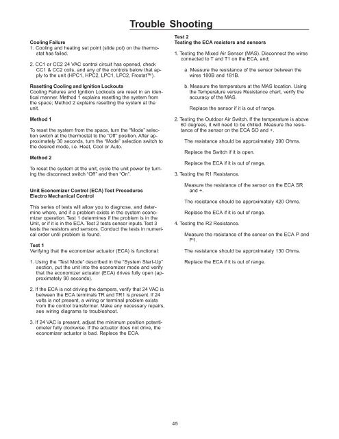
Trouble ShootingCooling Failure1. Cooling and heating set point (slide pot) on the thermostathas failed.2. CC1 or CC2 24 VAC control circuit has opened, checkCC1 & CC2 coils, and any of the controls below that applyto the unit (HPC1, HPC2, LPC1, LPC2, Frostat).Resetting Cooling and Ignition LockoutsCooling Failures and Ignition Lockouts are reset in an identicalmanner. Method 1 explains resetting the system fromthe space; Method 2 explains resetting the system at theunit.Method 1To reset the system from the space, turn the “Mode” selectionswitch at the thermostat to the “Off” position. After approximately30 seconds, turn the “Mode” selection switch tothe desired mode, i.e. Heat, Cool or Auto.Method 2To reset the system at the unit, cycle the unit power by turningthe disconnect switch “Off” and then “On”.Unit Economizer Control (ECA) Test ProceduresElectro Mechanical ControlThis series of tests will allow you to diagnose, and determinewhere, and if a problem exists in the system economizeroperation. Test 1 determines if the problem is in theUnit, or if it is in the ECA. Test 2 tests sensor inputs. Test 3tests the resistors and sensors. Conduct the tests in numericalorder until problem is found.Test 1Verifying that the economizer actuator (ECA) is functional:1. Using the “Test Mode” described in the “System Start-Up”section, put the unit into the economizer mode and verifythat the economizer actuator (ECA) drives fully open (approximately90 seconds).Test 2Testing the ECA resistors and sensors1. Testing the Mixed Air Sensor (MAS). Disconnect the wiresconnected to T and T1 on the ECA, and;a. Measure the resistance of the sensor between thewires 180B and 181B.b. Measure the temperature at the MAS location. Usingthe Temperature versus Resistance chart, verify theaccuracy of the MAS.Replace the sensor if it is out of range.2. Testing the Outdoor Air Switch. If the temperature is above60 degrees, it will need to be chilled. Measure the resistanceof the sensor on the ECA SO and +.The resistance should be approximately 390 Ohms.Replace the Switch if it is open.Replace the ECA if it is out of range.3. Testing the R1 Resistance.Measure the resistance of the sensor on the ECA SRand +.The resistance should be approximately 420 Ohms.Replace the ECA if it is out of range.4. Testing the R2 Resistance.Measure the resistance of the sensor on the ECA P andP1.The resistance should be approximately 130 Ohms.Replace the ECA if it is out of range.2. If the ECA is not driving the dampers, verify that 24 VAC isbetween the ECA terminals TR and TR1 is present. If 24volts is not present, a wiring or terminal problem existsfrom the control transformer. Make any necessary repairs,see wiring diagrams to troubleshoot.3. If 24 VAC is present, adjust the minimum position potentiometerfully clockwise. If the actuator does not drive, theeconomizer actuator is bad. Replace the ECA.45


