warning - Coastal Winair
warning - Coastal Winair
warning - Coastal Winair

Create successful ePaper yourself
Turn your PDF publications into a flip-book with our unique Google optimized e-Paper software.
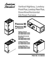
INSTALLATION GUIDEALL phases of this installation must comply with NATIONAL, STATE AND LOCAL CODESIMPORTANT — This Document is customer property and is to remain with this unit. Pleasereturn to service information pack upon completion of work.*PFWF071A93ABA*PFWF099A94ABA*PFWF132A95ABA*PFWF164A96ABA* May be “A” or “T”*PFWF201A97ABA*PFWF242A98ABA*PFWF286A99ABAOil Fired Water Boilerwith Three Pass Cast Iron Heat Exchanger®CUS18-CG03D1-4
1.0 Safety ConsiderationsIMPORTANT: Read this entire manual beforebeginning installation procedures.Read this manual carefully before attempting toinstall, operate, or perform maintenance on thisunit. Installation, service, and maintenance shouldbe performed by qualified technicians only.NOTE: “Warnings” and “Cautions” appear atappropriate places in this manual. Read these carefully.Your personal safety and the proper operationof this heating product require that you follow themcarefully. The manufacturer assumes no liabilityfor installations or service performed by independantdealers.Safety signal words are used to designate a degreeor level of seriousness associated with a particularhazard. The signal words for safety markings areWARNING and CAUTION.▲!WARNINGWARNING indicates a potentially hazardous situationwhich, if not avoided, could result in death or seriousinjury.▲!CAUTIONCAUTION indicates a potentially hazardous situationwhich, if not avoided, may result in minor ormoderate injury. It is also used to alert againstunsafe practices and hazards involving only propertydamage.1.1 WARNINGS▲!WARNINGTHE INFORMATION IN THIS GUIDE IS FOR USEBY INDIVIDUALS HAVING ADEQUATE BACK-GROUND OF ELECTRICAL AND MECHANICALEXPERIENCE. ANY ATTEMPTS AT PLUMBING,INSTALLING OR REPAIRING A BOILER MAYRESULT IN PERSONAL INJURY AND/OR PRO-PERTY DAMAGE. THE MANUFACTURER ORSELLER CANNOT BE RESPONSIBLE FOR THEINTERPRETATION OF THIS INFORMATION,NOR CAN IT ASSUME ANY LIABILITY IN CON-NECTION WITH ITS USE.▲!WARNINGELECTRICAL HAZARDDISCONNECT POWER BEFORE INSTALLINGOR SERVICING. FAILURE TO FOLLOW THISWARNING COULD RESULT IN SERIOUS INJURY,DEATH, OR PROPERTY DAMAGE.▲!WARNINGBURN HAZARDALLOW BOILER TO COOL DOWN PRIOR TOSERVICING OR PERFORMING MAINTENANCE.FAILURE TO FOLLOW THIS WARNING COULDRESULT IN SERIOUS INJURY, DEATH, OR PRO-PERTY DAMAGE.▲!WARNINGSAFETY HAZARDDO NOT BYPASS SAFETY CONTROLS. FAILURETO FOLLOW THIS WARNING COULD RESULTIN SERIOUS INJURY, DEATH, OR PROPERTYDAMAGE.▲!WARNINGCARBON MONOXIDE POISONING HAZARDFOLLOW THE INSTALLATION AND OPERATIONINSTRUCTIONS FOR THE VENTING SYSTEMOPERATION. FAILURE TO FOLLOW THIS WAR-NING COULD RESULT IN SERIOUS INJURY,DEATH, OR PROPERTY DAMAGE.▲!WARNINGFIRE HAZARDDO NOT INSTALL THIS BOILER DIRECTLY ONCARPETING. FAILURE TO FOLLOW THIS WAR-NING COULD RESULT IN SERIOUS INJURY,DEATH, OR PROPERTY DAMAGE.NOTE: This product is approved for installation oncombustible flooring materials except for carpet.▲!WARNINGFIRE HAZARDDO NOT INSTALL THIS BOILER WHERE FLAM-MABLE LIQUIDS ARE STORED OR WHEREFLAMMABLE VAPORS ARE PRESENT. FAILURETO FOLLOW THIS WARNING COULD RESULTIN SERIOUS INJURY, DEATH, OR PROPERTYDAMAGE.▲!WARNINGHEAVY OBJECT HAZARDA BOILER IS A HEAVY OBJECT. DO NOTHANDLE OR WORK UNDER A BOILER WITHOUTPROPERLY SECURING IT THROUGH SHORING,BLOCKING OR CRIBBING. FOLLOW ALL STATEAND FEDERAL CODES AND OSHA REGULA-TIONS AND GUIDELINES FOR HANDLING THEBOILER DURING INSTALLATION AND SERVI-CING. FAILURE TO FOLLOW THIS WARNINGCOULD RESULT IN SERIOUS INJURY, DEATH,OR PROPERTY DAMAGE.18-CG03D1-42
▲!WARNINGSAFETY HAZARDTHESE BOILERS ARE NOT APPROVED ORINTENDED FOR INSTALLATION IN MANU-FACTURED (MOBILE) HOUSING, TRAILERS,OR RECREATIONAL VEHICLES. FAILURETO FOLLOW THIS WARNING COULD RESULTIN SERIOUS INJURY, DEATH, OR PROPERTYDAMAGE.▲!WARNINGWATER DAMAGE HAZARDDO NOT USE THIS UNIT IF ANY PART HASBEEN UNDER WATER. IMMEDIATELY CALLA QUALIFIED SERVICE TECHNICIAN TO INS-PECT THE BOILER AND TO REPLACE ANYPART OF THE CONTROL SYSTEM AND ANY GASCONTROL WHICH HAS BEEN UNDER WATER.FAILURE TO FOLLOW THIS WARNING COULDRESULT IN SERIOUS INJURY, DEATH, OR PRO-PERTY DAMAGE.▲!WARNINGBURN HAZARDBEFORE OPENING THE BOILER DOOR,DISCONNECT BURNER CORD AT THE PLUG.FAILURE TO FOLLOW THIS WARNING COULDRESULT IN SERIOUS INJURY, DEATH, OR PRO-PERTY DAMAGE.PR0PERTY DAMAGE.▲!WARNINGIf the information in this manual is not followed exactly,a fire or explosion may result causing propertydamage, personal injury or loss of life.— Do not store or use gasoline or other flammablevapors or liquids in the vicinity of this or anyother appliance.— WHAT TO DO IF YOU SMELL GAS• Do not try to light any appliance.• Do not touch any electrical switch;do not use any phone in your building.• Immediately call your gas supplier from aneighbor’s phone. Follow the gas supplier’sinstructions.• If you cannot reach your gas supplier,call the fire department.— DO NOT RELY ON SMELL ALONE TO DETECTLEAKS. DUE TO VARIOUS FACTORS, YOU MAYNOT BE ABLE TO SMELL FUEL GASES.• U.L. recognized fuel gas and CO detectors arerecommended in all applications, and theirinstallation should be in accordance with themanufacturer's recommendations and/or locallaws, rules, regulations, or customs.— Installation and service must be performed by aqualified installer, service agency or the gassupplier.▲!WARNINGCARBON MONOXIDE POISONING HAZARDFailure to follow the steps outlined below for eachappliance connected to the venting system beingplaced into operation could result in carbon monoxidepoisoning or death.The following steps shall be followed for each applianceconnected to the venting system being placed intooperation, while all other appliances connected to theventing system are not in operation:1. Seal any unused openings in the venting system.2. Inspect the venting system for proper size andhorizontal pitch, as required in the National Fuel GasCode, ANSI Z223.1/NFPA 54 or the CAN/CGA B149Installation Codes and these instructions. Determinethat there is no blockage or restriction, leakage,corrosion and other deficiencies which could cause anunsafe condition.3. As far as practical, close all building doors andwindows and all doors between the space in which theappliance(s) connected to the venting system arelocated and other spaces of the building.4. Close fireplace dampers.5. Turn on clothes dryers and any appliance notconnected to the venting system. Turn on any exhaustfans, such as range hoods and bathroom exhausts, sothey are operating at maximum speed. Do not operatea summer exhaust fan.6. Follow the lighting instructions. Place the appliancebeing inspected into operation. Adjust the thermostatso appliance is operating continuously.7. If improper venting is observed during any of the abovetests, the venting system must be corrected inaccordance with the National Fuel Gas Code,ANSI Z221.1/NFPA 54 and/or CAN/CGA B149Installation Codes.8. After it has been determined that each applianceconnected to the venting system properly vents wheretested as outlined above, return doors, windows,exhaust fans, fireplace dampers and any other gas-firedburning appliance to their previous conditions of use.▲!WARNINGEXPOSED FLAMEBEFORE OPENING BOILER DOOR, DISCON-NECT ELECTRICAL POWER AND UNPLUGBURNER ELECTICAL CORD. FAILURE TOFOLLOW THIS WARNING COULD RESULT ININJURY, DEATH OR PROPERTY DAMAGE.The following <strong>warning</strong> complies with State of California law, Proposition 65.▲!WARNINGHAZARDOUS GASES!EXPOSURE TO FUEL SUBSTANCES OR BY-PRODUCTSOF INCOMPLETE FUEL COMBUSTION IS BELIEVED BYTHE STATE OF CALIFORNIA TO CAUSE CANCER, BIRTHDEFECTS, OR OTHER REPRODUCTIVE HARM.18-CG03D1-43
The following <strong>warning</strong> complies with State of California law, Proposition 65.1.2 CAUTIONS▲!CAUTIONDo NOT install the boiler in a corrosive or contaminatedatmosphere.18-CG03D1-4▲!WARNINGThis product contains fiberglass wool insulation!Fiberglass dust and ceramic fibers are believed by theState of California to cause cancer through inhalation.Glasswool fibers may also cause respiratory, skin, oreye irritation.PRECAUTIONARY MEASURES● Avoid breathing fiberglass dust.● Use a NIOSH approved dust/mist respirator.● Avoid contact with the skin or eyes. Wear long-sleeved,loose-fitting clothing, gloves, and eye protection.● Wash clothes separately from other clothing: rinsewasher thoroughly.● Operations such as sawing, blowing, tear-out, andspraying may generate fiber concentrations requiringadditional respiratory protection. Use the appropriateNIOSH approved respirator in these situations.FIRST AID MEASURESEye Contact – Flush eyes with water to remove dust.If symptoms persist, seek medicalattention.Skin Contact – Wash affected areas gently with soapand warm water after handling.▲!CAUTIONVerify system is leak free at startup. Failure tofollow this Caution will result in a continuous flow ofmake up water leading to premature heat exchangerfailure.1.3 NotesDuring routine boiler maintenance check integrity ofsystem to be sure there are no leaks. Minerals willbuild up inside the heat exchanger sections reducingperformance and will cause section failure. Theadditional oxygen added to the system from make upwater speeds corrosion inside the heat exchanger.The following notes must be followed during theinstallation, servicing, and operation of this boiler:1. This device must only be used for the purpose forwhich it is specially designed. This boiler is designedto heat water to a temperature below 200°Ffor circulation in a closed hydronic system.2. The manufacturer of this equipment assumesno liability for any damages resulting from unauthorized modifications made to the boiler, or anycomponents thereof, or improper installation ofthe boiler in the field. Furthermore, any such fieldmodifications VOID THE WARRANTY and placeresponsibility for safe and reliable operation of theboiler on those who performed the modification(s).3. These instructions DO NOT cover all variations insystems or provide for every possible contingency.Should further information be desired or particularproblems arise which are not covered sufficientlyby this manual, contact your local distributor forassistance.4. Use only No. 2 fuel oil per the boiler rating plate orNo. 2 fuel oil with bio-diesel fuel content no greaterthan 5% by volume.5. Install this boiler only in a location and position asspecified in these instructions.6. Provide adequate combustion and ventilation air tothe boiler space as specified in “Air for Combustionand Ventilation” (page 18), of these instructions.7. Combustion products must be discharged outdoors.Connect this boiler to an approved vent systemonly, as specified in Standard for the Installationof Oil-Burning Equipment, NFPA 31 – (most recentedition).8. Always install the boiler to operate within the boiler’stemperature operating range and install the specifiedASME approved pressure relief valve for the boiler.See the Service Facts that ship with the boiler forrelief valve specifications. The part number for therelief valve is included on the functional unit partslist that ships with the boiler.9. An oil-fired boiler for installation in a residentialgarage must be installed as specified in “InstallationLocation” section of these instructions.10. The boiler may be used for temporary heating ofbuildings or structures under construction only whenthe following conditions have been met:a. The boiler venting system must be complete andinstalled per manufacturers instructions.b. The boiler is controlled only by a room thermostat(no field jumpers).c. The boiler input rate and temperature rise must beverified to be within nameplate marking.e. 100% of the boiler combustion air requirement mustcome from outside the structure.f. Clean the boiler upon substantial completion of theconstruction process, and verify boiler operatingconditions including ignition, input rate, supply andreturn water temperature and venting, according tothe manufacturer’s instructions.g. Verify system is leak free at startup.11. Wear appropriate gloves, arm sleeve protectors,safety shoes, and eye equipment when servicing ormaintaining this equipment.12. Maintenance and cleaning should be performedat least once every year.NOTE: This product must be gas piped by alicensed Plumber or Gas Fitter in the Commonwealthof Massachusetts.4
Table of Contents1.0 Safety considerations ................................................................................. 21.1 Warnings .................................................................................................................21.2 Cautions ..................................................................................................................41.3 Notes .......................................................................................................................42.0 Pre-Installation Information & Instructions ............................................ 62.1 Parts Included ........................................................................................................62.2 General Specifications ..........................................................................................72.3 Codes and Regulations ..........................................................................................92.4 Locations and Clearances ......................................................................................92.5 Outline Drawings .................................................................................................103.0 Installation Instructions .......................................................................... 113.1 Moving Boiler .......................................................................................................113.2 Setting Boiler .......................................................................................................123.3 Uncrating Boiler ..................................................................................................123.4 Leveling Boiler .....................................................................................................123.5 Water Connections and Piping Diagrams ...........................................................123.6 Combustion Air and Ventilation ..........................................................................183.7 Flue / Chimney / Vent Connector ........................................................................203.8 Boiler Swing Door Conversion ............................................................................273.9 Oil Burner Installation ........................................................................................303.10 Optional Manual Reset Water Temperature Limit Installation .....................443.11 Electrical Connections .......................................................................................503.12 Supply Water Thermostat (SWT) Settings above 180°F ..................................514.0 Technical Data .......................................................................................... 524.1 Electrical Diagram ...............................................................................................524.2 Schematic Diagram ..............................................................................................534.3 Field Wiring Diagrams ........................................................................................544.4 Start-up and Adjustment .....................................................................................585.0 Appendix ...............................................................................................................6318-CG03D1-45
Pressure TemperaturegaugeBlank *Supply WaterThermostatOn/OffVentCover Plate forFuture OptionalAccessorySupplyBurner assemblymounting holesSightglassSwing Door - Factoryinstalled hinges on right- field convertible to left1-1/4" Plug2.0 Pre-Installation Information &InstructionsMaterial in this shipment has been inspectedat the factory and released to the transportationagency without known damage. Inspectexterior of crate for evidence of rough handlingin shipment. Unpack carefully after movingequipment to approximate location. If damageto contents is found, report the damage immediatelyto the delivering agency.Oil Boiler PackagingNOTE: Fittings, valves and adapters shipped withthe boiler are located in the combustion chamber.Remove them by pulling them out of the combustionchamber through the burner hole in the boiler door.Oil boilers will ship factory assembled as a package.Certain components like the draft control, pressurerelief valve and the boiler drain are included with theboiler. These components require installation. Optionalor locally required controls like low water cutoffs,supplied by installer, require field installation. Otherhydronic system components like circulating pump(s),18-CG03D1-46* Optional ManualHigh Limit ResetBoiler Feet▲!WARNINGBurn HazardBefore opening the boiler door, disconnectburner cord plug. Failure to follow this <strong>warning</strong>could result in injury, death or propertydamage.Figure 1ReturnBoiler DrainNOTE: Included with BoilerShip With Hardware,Field Installedair vents, expansion tanks, pressure regulators ,hydronic controls, backflow preventers, etc… will besupplied by the installer. Field installation is required.2.1 Parts Includeda) Oil Fired Boiler with 3 pass cast iron heatexchangerb) Factory installed High Temperature LimitSwitch with auto resetc) Factory installed Supply Water Thermostatd) Factory installed On-Off service switche) Factory installed Pressure TemperatureGaugef) 6” Draft Regulator, installation required.g) ASME 3/4” NPT male, 30psi Relief Valve- installation requiredh) 4 Double End Threaded Studs and 4 LockingWasher Hex Head Nuts for burner installationi) 1-1/4” NPT male x 1-1/2” NPT male x 3/4”NPT female Supply Teej) 1-1/4” NPT male x 1-1/2” NPT male ReturnNipplek) Brass Boiler Drain Valve, 1/2” NPT male x3/4” NH male hose coupling threads (1/4 turnopen or close depending on starting position)l) 1/2” NPT male x 1/2” NPT female boilerdrain adapterm) Ship with literature package - Installer’sGuide, Service Facts, Functional Unit Partslist, and User’s Information Guiden) Factory installed oil burner Wiring Harnesswith 7 pin connector
2.2 General SpecificationsTable 1 - General SpecificationsModel 1 *PFWF071A93ABA *PFWF099A94ABA *PFWF132A95ABAInput BTU/hr 71,000 99,000 132,000DOE Output BTU/hr 61,000 86,000 115,000I=B=R Net BTU/hr 53,000 75,000 100,000Efficiency - AFUE 85.5 85.7 85.9Electrical Power SupplyMinimum Circuit Ampacity - ampsMaximum Overcurrent Protection - ampsNominal Flue Outlet Dia. - inches (tapered) 5115 volts / 1 phase / 60 hertzless than 12.0155 5No. of Heat Exchanger Passes 3 3 3No. of Sections 3 4 5Water Content - Gallons 3.4 4.5 5.56Supply Water Connection - NPT female (in casting) 1-1/4" 1-1/4" 1-1/4"6Return Water Connection - NPT female (in casting) 1-1/4" 1-1/4" 1-1/4"Maximm Working Pressure - PSIG 5 60.0 60.0 60.0Combustion Chamber Pressre Drop - in w.c. 0.02 0.04 0.08Combustion Chamber Volume - Cubic Feet 0.87 1.12 1.37Water Pressure Drop 10 0 Td-FtHead 0.2 0.4 0.7Water Pressure Drop 20 0 Td-FtHead 0.1 0.1 0.2Water Pressure Drop 30 0 Td-FtHead - - 0.1Riello Non Direct Vent (40 Series) 2,3, 4 BAYRAF03ABURNA BAYRAF03ABURNA BAYRAF05ABURNARiello Direct Vent (40 Series) 2,3,4 BAYRBF03ABURNA BAYRBF03ABURNA BAYRBF05ABURNACrated Dimensions - inches (H x W x D) 40-3/16 x 24-13/16 x 23-5/8 40-3/16 x 28-3/4 x 23-5/8 40-3/16 x 32-11/16 x 23-5/8Ship Weight (Lbs) / Net (Lbs) 294 / 262 360 / 326 429 / 390Notes1. * May be "A" or "T"2. Oil burner is purchased separately as an accessory. Ships pre-assembled. Burner cord pre-wired with 7 pin plug that connects to boiler3. BAYRAF03 & BAYRBF03 burners ship with a factory installed nozzle for use with *PFWF071A. An additional nozzle, which requires field installation, isincluded for use with *PFWF099A4. BAYRAF05 and BAYRBF05 burners ship with a factory installed nozzle for use with *PFWF132A. Two additional nozzles are included, which requirefield installation; one each for use with *PFWF164A and *PFWF201A5. Boiler is shipped with 30 psi ASME Pressure Relief Valve6. Boiler ships with straight nipples. Nipples are 1-1/4" NPT male x 1-1/2" NPT male and 1-1/4"NPT male x 1-1/2" NPT male x 3/4" NPT female.18-CG03D1-47
Table 1 - General Specifications (Continued)Model 1 *PFWF164A96ABA *PFWF201A97ABAInput BTU/hr 164,000 201,000DOE BTU/hr 143,000 176,000I=B=R Net BTU/hr 125,000 153,000Efficiency - AFUE 86.1 86.3Electrical Power SupplyMinimum Circuit Ampacity - ampsMaximum Overcurrent Protection115volts/1phase/60hertzless than 12.015Nominal Flue Outlet Dia. - inches (tapered) 5 5No. of Heat Exchanger Passes 3 3No. of Sections 6 7Water Content - Gallons 6.7 7.96Supply Water Connection - NPT female (in casting) 1-1/4" 1-1/4"6Return Water Connection - NPT female (in casting) 1-1/4" 1-1/4"Maximm Working Pressure - PSIG 5 60.0 60.0Combustion Chamber Pressre Drop - in w.c. 0.12 0.14Combustion Chamber Volume - Cubic Feet 1.62 1.87Water Pressure Drop 10 0 Td-FtHead 1.1 1.6Water Pressure Drop 20 0 Td-FtHead 0.3 0.5Water Pressure Drop 30 0 Td-FtHead 0.2 0.2Riello Non Direct Vent (40 Series) 2,3 BAYRAF05ABURNA BAYRAF05ABURNARiello Direct Vent (40 Series) 2,3 BAYRBF05ABURNA BAYRBF05ABURNACrated Dimensions - inches (H xWxD) 40-3/16 x 36-5/8 x 23-5/8 40-3/16 x 40-9/16 x 23-5/8Ship Weight (Lbs) / Net (Lbs) 497 / 454 565 / 518Model 1 *PFWF242A98ABA *PFWF286A99ABAInput BTU/hr 242,000 286,000DOE Output BTU/hr 212,000 252,000I=B=R Net BTU/hr 185,000 219,000Efficiency - AFUE 86.5 86.7Electrical Power SupplyMinimum Circuit Ampacity - ampsMaximum Overcurrent Protection15Nominal Flue Outlet Dia. - inches (tapered) 5 5No. of Heat Exchanger Passes 3 3No. of Sections 8 9Water Content - Gallons 9.1 10.36Supply Water Connection - NPT female (in casting) 1-1/4" 1-1/4"Return Water Connection - NPT female (in casting)61-1/4" 1-1/4"Maximm Working Pressure - PSIG 5 60.0 60.0Combustion Chamber Pressre Drop - in w.c. 0.16 0.20Combustion Chamber Volume - Cubic Feet 2.12 2.37Water Pressure Drop 10 0 Td-FtHead 2.3 3.2Water Pressure Drop 20 0 Td-FtHead 0.6 0.9Water Pressure Drop 30 0 Td-FtHead 0.3 0.4Riello Non Direct Vent (40 Series) 2,4 BAYRAF10ABURNA BAYRAF10ABURNARiello Direct Vent (40 Series) 2,4 - -Crated Dimensions - inches (H xWxD) 40-3/16 x 44-1/2 x 23-5/8 40-3/16 x 48-7/16 x 23-5/8Ship Weight (Lbs) / Net (Lbs) 632 / 582 698 / 646Notes1. * May be "A" or "T"2. Riello burner purchased separately as an accessory. Ships pre-assembled. Burner cord pre-wired with 7 pin plug thatconnects to boiler5. Boiler is shipped with 30 psi ASME Pressure Relief Valve6. Boiler ships with straight nipples. Nipples are 1-1/4" NPT male x 1-1/2" NPT male and 1-1/4"NPT male x 1-1/2" NPT male x 3/4" NPT female.18-CG03D1-48115 volts / 1 phase / 60 hertzless than 12.03. BAYRAF05 and BAYRBF05 ship with a factory installed nozzle for use with *PFWF132A. Two additional nozzles areincluded which require field installation; one each for use with *PFWF164A and *PFWF201A4. BAYRAF10 ships with a factory installed nozzle for use with *PFWF242A. An additional nozzle, which requires fieldinstallation, is included for use with *PFWF286A
2.3 Codes & RegulationsThe manufacturer assumes no responsibility forequipment installed in violation of any code or regulation.Installation of this oil-fired boiler must be performedby a qualified installer in accordance with all localcodes and authorities having jurisdiction. Codesand local utility requirements governing the installationof boiler equipment, wiring, plumbing andflue connections must be adhered to. In the absenceof local governing codes, installation shall conformto these instructions and to the regulations of theNational Fire Protection Association’s Standard forthe Installation of Oil-Burning Equipment, NFPA 31- (most recent edition), and the National ElectricalCode, ANSI/NFPA 70 – (most recent edition)The most recent edition of the American NationalStandard NFPA 211, “Chimneys, fire places, vents,and solid fuel burning appliances” for venting requirementsand the most recent editions of AmericanSociety of Mechanical Engineers ASME CSD-1,“Controls and Safety Devices for Automatically FiredBoilers,” for assembly and operation of controls andsefety devices.Reference should be made to the most recent editionof the Canadian Standards Association CSAB139“Installation Code for Oil Burning Equipment” forrecommended installation porcedures in Canada.A qualified installer, also referred to in this instructionmanual as a “qualified heating dealer”, isan individual, or agency, properly licensed andexperienced to install and service oil-burningequipment in accordance with all local codesand ordinances.It is recommended that Manual J of the Air ConditioningContractors Association (ACCA) or A.R.I. 230be followed in estimating heating requirements.2.4 Locations & Clearances▲!WARNINGFIRE HAZARDDO NOT INSTALL THIS BOILER DIRECTLY ONCARPETING. FAILURE TO FOLLOW THIS WAR-NING COULD RESULT IN SERIOUS INJURY,DEATH, OR PROPERTY DAMAGE.NOTE: THIS PRODUCT IS APPROVED FORINSTALLATION ON COMBUSTIBLE FLOORING.DO NOT INSTALL ON CARPET.a) Location ConsiderationsBefore the boiler is moved into place, be sure toconsider the following requirements:1. Proximity to the chimney and available ventinglocations.2. For a utility room or closet installation, theentrance door must be wide enough to permitthe largest part of the boiler to pass throughthe doorway or allow sufficient clearance topermit the replacement of another appliance,e.g. a water heater, in the room and have enoughclearance for service on both sides and rear of theboiler to permit installation and service access.3. All clearances between the boiler and theenclosure must equal or exceed the minimumstated in the clearance table on the OutlineDrawings.4. Is there sufficient space for servicing the boilerand other equipment? A minimum of 36” frontand 36” top must be provided for service access tothe boiler. Any access door or panel must permitremoval of the largest component.5. Are the ventilation and combustion air openingslarge enought and will they remain unobstructed?If outside air is used, are the openingsset above the highest snow accumulation level?(See Combustion and Ventilation section)6. Ensure the floor structure will support theweight of the boiler. Ensure any stairs, pedastles,and floors will support the weight of theboiler, dolly, moving equipment and any personnelmoving the boiler.7. Locate the boiler so that all system componentsare protected from water damage duringoperation or service.8. In some applications, boilers may need to beraised above the floor level to reduce the risk ofwater damage.9. If the boiler is installed in a residential garage,it must be installed so the burner is locatedhigher than 18 inches above the floor. Also, theboiler must be located or protected to avoid physicaldamage from impacts by vehicles.10. Boilers must rest installed on sturdy, stable,and level surfaces.11. All boilers installed above the level of heatemitters must have a low water cut-off deviceinstalled. Refer to National, State or Local codesfor guidance.MINIMUM CLEARANCESMinimum clearances to combustible materials aremandatory to assure protection from fire hazardduring boiler operation. (Refer to the Standard forthe Installation of Oil-Burning Equipment, NFPA 31-latest edition, for definitions of combustible and noncombustiblematerials.)Service clearances, which are typically greater, mayexceed fire protection clearances. See Table 2.18-CG03D1-49
The minimum clearances from boiler casing surfaces to combustible materials are:Table 2(a) Leave at least 24” on oneMinimum Clearancesfor Combustion ces for Service the opposite sideMinimum Clearan-side of the boiler and 6” onTop 6” 36”(b) Though these are approvedclearances for these boilers,space must be providedRight Side 6” 24” (a)at the front (18 inches minimum,24-30 inches recom-Left Side 6” 6” (a)Front 18” 30” (b)mended) and at the rear ofthe boiler for access, service,Back 6” 24” (b)and replacement of the oilburner and other hydronicsystem components.2.5 Outline DrawingsFigure 2 - Dimensions and Connections19.685.394.1333.4622.055.0010.6320.873.945.39 5.39All dimensions are in inchesTable 3Model A a1 a2 a3in. in. in. in.*PFWF071A93ABA 17.0 1 1/4 1 1/4 1/2*PFWF099A94ABA 20.9 1 1/4 1 1/4 1/2*PFWF132A95ABA 24.9 1 1/4 1 1/4 1/2*PFWF164A96ABA 28.8 1 1/4 1 1/4 1/2*PFWF201A97ABA 32.8 1 1/4 1 1/4 1/2*PFWF242A98ABA 36.7 1 1/4 1 1/4 1/2*PFWF286A99ABA 40.6 1 1/4 1 1/4 1/2* May be “A” or “T”a1, a2, a3 are all NPT male18-CG03D1-410
3.0 Installation Instructions3.1 Moving Boiler to Installation Location▲!WARNINGSAFETY HAZARDWHEN MOVING THE BOILER TO THE INSTAL-LATION LOCATION, ENSURE THE STRUCTURE(I.E. FLOORS, STAIRS, PEDESTALS) CAN SUP-PORT THE WEIGHT OF THE BOILER, DOLLYAND OTHER MOVING EQUIPMENT AND THEPERSONNEL MOVING THE BOILER. FAILURETO FOLLOW THIS WARNING COULD RESULTIN SERIOUS INJURY, DEATH, OR PROPERTYDAMAGE.clips to the left and right jacket panels. SeeFigure 7. The metal control enclosure isremoved from the left and right jacket panelsby removing two phillips screws on eachside.d. Remove the left and right boiler jacketpanels and the rear boiler boiler jacket panelby removing the phillips screws and/or nutssecuring the panels.e. Move and set the boiler.f. Reassemble the boiler jacket. control paneland access panel. Leave the top panel offuntil the boiler is leveled.▲!CAUTIONSAFETY CAUTIONUse caution when inserting and removing safetyblocks. Make sure boiler will not fall off safetyblocks.Failure to obey caution could result in minor ormoderate injury.1. Move crated boiler as close as possible to thelocation to be installed.2. If the boiler can not be moved with crateassembled, uncrate the boiler first (see section3.3) and use an appliance dolly capable ofhandling the boiler weight to move the boilerto the selected location.3. If required, the boiler jacket may be removedto simplify handling. To remove the boilerjacket, follow the steps below.a. Remove the upper and lower front accesspanels (See Figure 5).b. Remove the top access panel. See Fig. 7.c. The control panel is lowered by removingtwo phillips screws that hold the attachmentFigure 4Figure 3Figure 518-CG03D1-411
3.2 Setting Boiler1. Verify the floor structure where the boiler willbe set can support the weight of the boiler.2. Locate the boiler so all components are protectedfrom water damage during operation.3. As required, raise the boiler above the floor levelto reduce the risk of water damage.4. Consult ANSI Z223.1 for garage applications.5. Move the boiler to the installation locationwith an appliance dolly capable of handlingthe boiler. If required, the boiler jacket may beremoved to simplify handling.3.3 Uncrating Boiler1. Cut the four corners of the crate as shown inFigure 3.2. Lift the crate off of the boiler. See Figure 4.3. Remove the front bottom access panel. SeeFigure 5. Locate and remove the four boltsholding the boiler to the wooden shipping base.3.4 Leveling the Boiler1. Place level on boiler. Adjust level of boiler byplacing shims under cast iron boiler as needed.3.5 Water Connections and PipingSystemsFigure 7Boiler Top PanelAttachmentClip▲!WARNINGCONTAMINATION HAZARD.ScrewControlPanelCoverAIR IN BOILER PIPING SYSTEM LEADS TOOXYGEN CONTAMINATING THE SYSTEM.OXYGEN CONTAMINATION LEADS TO CORRO-SION AND PREMATURE BOILER FAILURE. THEBOILER STANDARD LIMITED WARRANTY DOESNOT COVER OXYGEN CONTAMINATION OFBOILER OR SCALE DEPOSITS CAUSED BY MAKEUP WATER ADDED TO THE SYSTEM. FAILURETO FOLLOW THIS WARNING COULD RESULTIN SERIOUS INJURY, DEATH, OR PROPERTYDAMAGE.▲!CAUTIONIf the boiler is left operational and unattended for anyextended periods of time, provisions must be takenperiodically to ensure the system operation. This isespecially important in below freezing weather. If forany reason your boiler should fail to operate, damagecould result, such as frozen water pipes.NOTE: Do NOT use the water system pipes toground electrical appliances.PressureReliefValveReturnWaterNipple1-1/2”1-1/2”Hosecouplingthreads1-1/4”3/4”1/2”1/2”1-1/4”Drain AdapterDrain ValveSupplyWaterAdapterTeeFigure 6NOTE: Ensure the hydronic system is properlysupported so that no stress is applied to the boilerconnections.General Guidelines1) For good operation and long life of the boiler, thepiping system must be designed properly.2) Install air vents at any points in the supply andreturn pipes where air pockets could form. Also,install a discharge device at the lowest point in thesystem to allow complete draining of the system.3) If the boiler is installed at the lowest level pointof a single loop system or hydronic coils are usedupstream of air conditioning coils, a flow check valveshould be installed to prevent the natural migrationof hot water through the system in the curculator'soff cycle.18-CG03D1-412
4) The installer of the boiler is required to providea low water cutoff switch when installing theboiler above the distribution system. Consult localcodes which may require a low water cutoff for allinstallations regardless of boiler location. The lowwater cut off switch should discontinue burneroperation until proper water level is achieved.5) The return water temperature to the boiler mustbe above 110° F. The cases where this boiler isinstalled on systems with large volumes of water(for example - retro fitted gravity system or lowtemperature systems such as radiant floor systems),the installer is required to use one of the methodsof boiler protection described in this manual under"System Piping Diagrams" to protect the system.Pipe Connectionsa) The threads in the heat exchanger castingare 1-1/4” NPT female. Supply and Returnnipples that ship with the boiler are 1-1/2” NPTmale x 1-1/4” NPT male. See Figure 2 andFigure 6.b) Boiler drain requires installation. See Fig. 6.6) Install factory provided piping items as shownin Figure 6. These include the supply water adaptertee, the pressure relief valve, the return waternipple, the drain adapter, and the drain valve.. ▲!WARNINGSAFETY HAZARD.PRESSURE RELIEF VALVE OUTLET MUST BEROUTED TO WITHIN 6” OF A FLOOR DRAIN OROTHER AREA SAFE FOR DISCHARGE OF HOTWATER AND SAFE FROM FREEZING. THISPIPE MUST BE FULLY 3/4” IN SIZE THE ENTIRELENGTH AND IT MUST NOT CONTAIN ANYRESTRICTIONS, TRAPS, VALVES, PLUGS, ORCAPS. FAILURE TO FOLLOW THIS WARNINGCOULD RESULT IN SERIOUS INJURY, DEATH,OR PROPERTY DAMAGE.7) A 3/4” pipe must be routed from the outlet of thepressure relief valve to the nearest suitable drain.This pipe is not provided with the boiler.8) Before connecting the boiler to the hydronicsystem, carefully flush all the pipes of the systemwith water to remove residues or impurities thatcould affect the unit’s performance.9) Supply and return water connections are locatedon the back of the boiler. The installation of pipingshall be in accordance with National, State and localcodes.It is advisable to install on-off valves between theboiler and heating system and on the inlet and outletside of all hydronic system components for service.This allows the boiler or components to be isolatedfrom the system if necessary.Characteristics of the water systemIn the presence of water harder than 14 grains per gallon,we recommend the use of suitably conditioned waterin order to avoid possible scaling in the boiler, causedby hard water, or corrosion produced by aggressivewater. It should be remembered that, because of itslow thermal conductivity, even scaling of just a few mmthick causes significant overheating of the boiler wallswith consequent serious problems.Water treatment is indispensable in the case of verylarge systems (containing large amounts of water) orwith frequent introduction of replenishing water inthe system. If partial or total emptying of the systembecomes necessary under these conditions, it is advisableto refill it with treated water.Proper boiler operating pressuresThe system pressure when cold should be about 12psi.For correct operation of the boiler, when hot, its pressureshould be about 18-24 psi.Head Loss vs.Flow Chartfor All *PFWFModels18-CG03D1-413
I. Typical System Piping DiagramsTypical System Piping DiagramSingle Zone System - High Temperature with Low Mass Heat EmittersGlobeValveGlobeValveBack FlowPreventerPressureGaugeGlobeValveAirSeparatorPressureReducerFlowCheckReliefValveCirculatorPumpSupplyExhaustVent1Expansion TankBaseboardConvectionFin TubeReturnReturnwatertemperaturemustbeabove110 O FHeat EmitterBoiler1NOTES:Locate the circulator inlet close to the connection point of the expansion tank, but allow at least the equivalent of 10 to 12 pipediameters between the circulator pump inlet and the expansion tank to reduce the possibility of pump noise and facilitate air removal.Heat Emitter18-CG03D1-414
Typical System Piping DiagramPrimary Secondary Loop with 3-way Motorized ValveLow Temperature with Low Mass Heat Emittersor High Temperature with High or Low Mass Heat Emitters1Back FlowPreventerGlobeValvePressureGaugeGlobeValveGlobeValvePressureReducerAirSeparatorCirculatorPump 3-WayMotorized ValveSupplyReliefValveExhaustVent2Expansion Tank3CirculatorPumpSupply WaterTemperatureSensorReturn WaterTemperatureSensorReturnBoilerReturn water temperaturemust be above 110 O F312NOTES:Protects boiler from too low return water temperature and condensation.Locate the circulator inlet close to the connection point of the expansion tank, but allow at least the equivalent of 10 to 12 pipediameters between the circulator pump inlet and the expansion tank to reduce the possibility of pump noise and facilitate air removal.Close coupled TeesHeat Emitter18-CG03D1-415
Typical System Piping DiagramPrimary Secondary Loop with 4-way Motorized Valve with Circulator in Secondary Loop OnlyLow Temperarure with Low Mass Heat Emittersor High Temperature with High or Low Mass Heat Emitters1Back FlowPreventerGlobeValvePressureGaugeGlobeValveGlobeValvePressureReducerAirSeparatorCirculatorPumpSupply WaterTemperatureSensorReliefValveSupplyExhaustVent2Expansion Tank4-WayMotorized ValveReturn WaterTemperatureSensorReturnBoilerReturn water temperaturemust be above 110 O F12NOTES:Protects boiler from too low return water temperature and condensation.Locate the circulator inlet close to the connection point of the expansion tank, but allow at least the equivalent of 10 to 12 pipediameters between the circulator pump inlet and the expansion tank to reduce the possibility of pump noise and facilitate airremoval.Heat Emitter18-CG03D1-416
Typical System Piping DiagramPrimary Secondary Loop with 4-way Motorized Valvewith Circulators in Primary and Secondary LoopsLow Temperarure with Low Mass Heat Emittersor High Temperature with High or Low Mass Heat Emitters1GlobeValveBack FlowPreventerGlobeValvePressureGaugeGlobeValveCirculatorPumpSupply WaterTemperatureSensorPressureReducerAirSeparatorCirculatorPumpReliefValve34-WayMotorized ValveSupplyExhaustVent2Expansion Tank312ReturnBoilerReturn water temperaturemustbeabove110 O FReturn WaterTemperatureSensorNOTES:Protects boiler from too low return water temperature and condensation.Locate the circulator inlet close to the connection point of the expansion tank, but allow at least the equivalent of 10 to 12 pipediameters between the circulator pump inlet and the expansion tank to reduce the possibility of pump noise and facilitate air removal.Close coupled TeesHeat Emitter18-CG03D1-417
3.6 Combustion Air and Ventilation▲!WARNINGCARBON MONOXIDE POISIONING HAZARD!VENTILATION REQUIRED!OIL BOILER/BURNER COMBUSTION AIR OPE-NING MUST NOT BE OBSTRUCTED OR BLOC-KED. THESE OPENINGS SUPPLY COMBUSTIONAND VENTILATION AIR TO THE BOILER.FAILURE TO FOLLOW THIS WARNING COULDRESULT IN CARBON MONOXIDE POISONING ORDEATH.Important: All aspects of the installation of thisboiler, including materials, methods of providingcombustion air and methods of venting products ofcombustion to the outdoors must comply with all localcodes and the following national standards:1) CSA B139 (most recent edition) - Installation Codefor Oil Burning Equipment (Canada)2) NFPA 31 (most recent edition) - Standard for theInstallation of Oil Burning Equipment (US)3) NFPA 211 (most recent edition) - Standard forChimneys, Fireplaces, Vents, and Soild Fuel BurningAppliancesChloride, fluoride, iodide, and bromide bearing compoundswhen present, even in low concentrations, inair supplied for combustion to the boiler, can result inaccelerated and severe corrosion of the heat exchangerand/or the venting system. Often, householdchemicals contain chloride-bearing compounds. Thereare many compounds representative of this classificationof chemicals. A few common examples are:- Cleaning solvents- Varnish and paint removers- Bleaches- Fabric softeners- Water softener saltAvoid storing or using these chemicals within closeproximity to the boiler. In addition, avoid storing orusing any chemicals, of an unknown and possiblyflammable nature, in close proximity to the boiler. Ifit is necessary to store or use chemicals in the samespace as the boiler, the area should be well-ventilatedand all containers should be sealed when not in use.If possible, keep chemicals in a separate, well ventilated,room closed off from the boiler.The boiler shall be installed in a location within thebuilding that permits a satisfactory supply of air forcombustion, ventilation, and proper operation of theventing system. While all forms of building constructioncannot be covered in detail in this installer’sguide, this requirement may usually be met byapplication of one of the following methods in ordinarybuilding construction. However, applicable local18-CG03D1-418CONFINEDSPACEFigure 8LESS THAN 50 CU. FT.PER 1000 BTU/HR. INPUT ALLEQUIP. INSTALLEDFigure 9Figure 10
installation codes always take precedence and shallbe followed.The content of certain pertinent passages of NFPA31, (most recent edition) methods to obtain andensure adequate combustion airflow to the boilerhas been excerpted and, in some cases, paraphrasedbelow for reference purposes. Consult the Standardfor the Installation of Oil-Burning Equipment, NFPA31- (most recent edition) and Installation Code for OilBurning Equipment (Canada) CSA B139 (most recentedition), for special cases and further details.Boiler locations may be in “confined space” or “unconfinedspace.” However, if the boiler is installed in a“confined space,” combustion air must be provided bya means conforming to local or national codes. someexample methods are described herein.Confined SpaceConfined spaces, as shown in Figure 8, are installationswith less than 50 cubic feet of space per 1000BTU/hr input from all appliances installed in thespace. Air for combustion and ventilation requirementscan be supplied from inside the buildings infigure 9 or from the outdoors as in Figure 10.Utility Room (example of a confined space):a. In buildings of conventional construction withnormal air infiltration, two (2) permanent openingsconnecting to a well-ventilated crawl space, attic, oranother large, well-ventilated internal area shall beprovided. Each opening shall have a minimum freearea of one (1) square inch per 1000 BTUH of totalinput rate (sum of the individual appliance inputrates) of all appliances to be installed in the utilityroom. One opening should be located near, or in, theceiling of the room and the other should be locatednear, or in, the floor.b. In buildings of unusually tight construction(e.g. those having continuous water vapor barriers;tightly-fitting, or weather-stripped, doors and windows;and gasketed, caulked, or sealed outer walljoints and penetrations), wherein infiltration and airexchange with the outdoors is very limited (0.35 airchanges per hour, or less), provision must be made toprovide sufficient air for combustion. The followingmethod will usually be adequate to ensure sufficientairflow into the space:Provide two (2) permanent openings, one (1) locatedwithin 12 inches of the floor and one (1) within 12inches of the ceiling, or roof, of the room. Theseopenings shall allow for direct exchange of airbetween the room and outdoors. If required, ductingbetween the room and the outdoors shall beprovided.- For horizontally -oriented ducts, each opening shallhave a minimum free area of one (1) square inchper 2000 BTUH of the total input rate (sum of theUNCONFINEDSPACE50 CU. FT. OR MOREPER 1000 BTU/HR. INPUTALL EQUIP. INSTALLEDBoiler MaximumBTUH Input RatingTable 4Figure 11With 8 Ft. Ceiling MinimumArea in Square Feetof Unconfined Space80,000 500100,000 625140,000 875170,000 1,063180,000 1,125210,000 1,313250,000 1,563290,000 1,813individual appliance input rates) of all appliancesto be installed in the room.- For vertically -oriented ducts, the minimum freearea may be reduced to one (1) square inch per4000 BTUH of the total input rate (sum of theindividual appliance input rates) of all appliancesto be installed in the room.- The minimum dimension of any air opening shallnot be less than 3-inches.- When an opening in the outside wall must be provided,it should be furnished with properly screenedmetal sleeves.Unconfined SpaceUnconfined spaces are defined in Figure 11 and Table4. These spaces may have adequate air to providefor combustion, ventilation, and dilution of flue gasesfrom infiltration. Buildings with tight construction(for example, weather stripping, heavy insulated,caulked, with vapor barrier, etc. may need additionalair provided as described for confined space. Anunconfined space is any space where the volume isequal to or greater than 50 cubic foot per 1000 BTU/hr or the aggregate input rating of all appliancesinstalled therein.18-CG03D1-419
Full Basement (example of an unconfined space):a. Where a boiler is installed in a full basement,in a building of conventional constructionwith normal air infiltration, infiltrationis normally adequate to provide air for combustionand ventilation.b. In buildings of unusually tight construction(such as those where weather strippingand storm sash windows are used, and wherebasement windows are also weather-stripped),one (1) permanent opening connectingto a well-ventilated attic, or with the outdoorsshall be provided, using a duct, if necessary.This opening shall have a minimum free areaof one (1) square inch per 5000 BTUH of totalinput rate (sum of the individual applianceinput rates) of all appliances to be installedin the basement.When an opening in the outside wall must beprovided, it should be furnished with properlyscreened metal sleeves.If an exhaust fan, additional air consuming machines(e.g. an air compressor), or a return air grill ispresent in the boiler room, there should be increasedconcern about providing adequate airflow to theboiler. Additional efforts may be required to assurean adequate supply of combustion and ventilation airis available to the boiler under all conditions.Procedure to Determine if Space is Confined:NOTE: Rooms without doors are considered part ofspace.1. Calculate volume of space.2. Add input BTU/hr from all appliances in space.3. Divide the total space volume by the total input ofall appliances.Total Cubic Feet of Space / TotalAppliance Input BTU/hr4. If the result is greater than or equal to 50 cubicfoot of space per 1000 BTU/hr, the space is consideredunconfined.5. If the result is less that 50 cubic feet of space per1000 BTU/hr, the construction is considered confined.6. Oil fired boilers located in an unconfined space of abuilding with traditional construction (loose), typicallyhave enough infiltration air for combustion andventilation.7. Outdoor air may also be provided by combiningthe following *PFWF boilers and direct vent oil burnersdesigned to duct outdoor air directly to the burner:a. *PFWF071 and BAYRBF03ABURNAb. *PFWF099 and BAYRBF03ABURNAc. *PFWF132 and BAYRBF05ABURNAd. *PFWF164 and BAYRBF05ABURNAe. *PFWF201 and BAYRBF05ABURNA(See Direct Vent Instructions section)If an exhaust fan, additional air consuming machines(e.g. an air compressor), or a return air grill ispresent in the boiler room, there should be increasedconcern about providing adequate airflow to theboiler. Additional efforts may be required to assurean adequate supply of combustion and ventilation airis available to the boiler under all conditions.3.7 Flue/Vent/Chimney/Vent Connector▲!WARNINGCARBON MONOXIDE HAZARDIN THIS APPLICATION, THE FLUE GAS VENTPIPE IS AT A POSITIVE PRESSURE. THE VENTSYSTEM MANUFACTURER’S INSTALLATIONINSTRUCTIONS MUST BE FOLLOWED PRECI-SELY. THE COMBUSTION AIR INLET PIPE ANDFLUE GAS VENT PIPE MUST BE PROPERLYSEALED. FAILURE TO DO THIS COULD ALLOWPRODUCTS OF COMBUSTION INTO THE HOME,RESULTING IN PERSONAL INJURY OR LOSS OFLIFE.▲!WARNINGFIRE HAZARDDO NOT ENCLOSE THE FLUE GAS VENT PIPE.IF AIR CIRCULATION IS BLOCKED AROUND THEFLUE GAS VENT PIPE, IT COULD OVERHEATAND A FIRE MAY RESULT. FAILURE TO FOLLOWTHIS WARNING COULD RESULT IN SERIOUSINJURY, DEATH, OR PROPERTY DAMAGE.▲!CAUTIONPROPER VENTING REQUIRED!DO NOT install a manual damper in the chimney orvent connector.Thermally- activated type vent dampers are NOTALLOWED for use on these boilers.Venting systems in the United States must complywith NFPA 31, and in Canada, with CSA B139 for ofoil burning equipmentUse of Existing/Masonary ChimneysDo not use an existing chimney unlessproperly relined using UL Listed and CSACertified components installed in accordancewith local and national codes includingNFPA 211.18-CG03D1-420
Chimney InspectionThe chimney, vent, or any passageway for the stackgases to flow to the outdoor atmosphere is a veryimportant part of the heating system. No boiler,regardless of the efficiency of the design, can performsatisfactorily when the chimney to which it is connectedis inadequate or in poor condition.Any of the following symptoms may indicate a chimneyhas severe structural damage and is unsuitablefor use:- Chimney appears to be leaning to the side.- Chimney appears to have structural damage, i.e.loose or missing blocks or bricks, or excessive deteriorationat mortar joints.- Tile liner damaged or missing.- Flue gas leakage along the length of the chimneybetween the chimney connector and discharge termination.- Excessive corrosion at the cleanout port or at thechimney connector entrance into the chimney.- Structural debris, i.e. mortar or tile liner flakes, inbase of the flue way.A qualified person shall inspect the chimney to confirmit is correctly sized for the application, properlyconstructed, and in sound condition. Refer to theStandard for the Installation of Oil-Burning Equipment,NFPA 31-(most recent edition), for details onproper chimney sizing and construction. If needed,the chimney should be cleaned before installing theboiler. Any accumulation of dirt or debris at thebottom of the flue should be removed.Chimney Sizing:The boiler must be connected to an adequate chimneyor an approved vent in accordance with these instructions.An adequate chimney is one that is sealedand lined with the capability of producing a (-).04”WC flue draft and having the capacity to handle theamount of stack gases that are introduced into it. Achimney with an internal construction of corrosionresistant tile, stainless steel, or some other materialthat will withstand flue gas temperatures up to 900°Fis required.The following are common chimney requirementsnecessary for the boiler to operate correctly:A masonry chimney serving an oil fired boiler mustcomply with local codes and NFPA Standard forChimneys, Fireplaces, Vents, and Solid Fuel BurningAppliances (NFPA211-1996 or latest edition).The inside area of the chimney liner should equal, atminimum, the area of the vent pipe exiting the boiler-EXAMPLE: π x r 2 = Area of Pipe (sq. in.)r = radius of pipeπ = 3.1417Flue Pipe Diameter = 6” [pipe Radius = ½diameter of pipe = ½ ( (6 in.) = 3in.]π x 3 2 = 28 sq. in.NOTE: This formula calculates the minimum insidearea of the chimney. If more than one appliancevent connector pipe is connected to the chimney, theminimum inside area of the chimney should be equalto the area of the largest vent pipe plus one half thearea of any additional vent pipes. If the chimney istoo large or condensation has been a problem in thepast refer to the NFPA Standard for the Installationof Oil Burning Equipment (NFPA31-most currentedition) Appendix E for proper liner sizing.Figure 13Proper chimney termination heightfor pitched roofsChimney Height:The chimney shall terminate at least 3 feet above thehighest point where it passes through the roof of abuilding and at least 2 feet higher than any portionof a building within a horizontal distance of 10 feet.(See Fig. 13).All installations and services must be performed byqualified service personnel.18-CG03D1-421
If the chimney penetrates a roof more than 10 feetfrom a ridge, wall or parapet, a minimum of 3 feetabove roof or exit point must be maintained. SeeFigure 13.If the roof is flat rather than the normal residentialPitched roof, refer to Figure 14 for proper clearances.Figure 14A thimble should be used to connect the vent connectorpipe to the chimney so that the vent connectorpipe may be readily removed in case of inspection orreplacement.In cases where the chimney extends to the basementfloor, the draft can usually be improved by filling thebase of the chimney with sand to within 12 inches ofthe vent connector pipe after relocating the clean-outdoor. (See Fig. 16).Proper chimney termination height for fIt is desirable to install the shortest vent connector(also referred to as a flue or chimney connector) possiblewith the fewest number of fittings, i.e. transitionsand elbows.Generally, 24 Ga. or heavier, single wall, lock seamtype,galvanized steel vent pipe of the proper diameter(see boiler general product specifications) andfittings are satisfactory materials for the fabricationof a vent connector. However, always consult localcodes and authorities for specific minimum requirements.All horizontal sections of the vent connector mustslope upward not less than ¼ inch per foot from theboiler to the chimney. Long horizontal sections of theventing system must be supported at least every five(5) feet with metal straps to prevent sagging of thevent piping.Secure all joints in the vent connector with sheetmetal screws or equivalent fasteners.The vent connector pipe should extend only to (andnot beyond) the inside wall of the chimney (See Fig.15).Figure 16Suggested method to improve chimney draft.All joints of the chimney must be tightly sealed. Theinside of the chimney should be free of any obstructions,such as loose brick, broken pieces of tile, orcorroded metal.All chimney clean-out doors and flue connectionsmust fit tightly so they will seal to avoid air leaks.If chimney flues are divided or there are multipleflues within one chimney, make sure there are noopenings in the partition separating the divided orindividual flues.The vent connector pipe must not pass through acombustible wall or partition unless adequate protectionis provided at the passageway. An acceptablepassageway could be either an approved, ventilatedmetal thimble which is at least 12 inches larger indiameter than the vent connector pipe, or brick workwhich is at least 8 inches thick constructed into thewall and surrounding the vent connector pipe. (SeeFig. 17).Figure15Proper insertion of the vent connector in chimney.18-CG03D1-422
Figure 17Table 5Reduction of Clearances with Specified Forms of ProtectionVENT PIPEVENT PIPEType of ProtectionAllowable Clearancewith Specified Protection(in.)Suggested method to acommodate ventconnector passage through a wallcomposed of combustible material.The vent connector pipe between the boiler and chimneyshall be of equal diameter as the flue outlet of theboiler.The vent connector pipe must be made of 24 gauge (orthicker) corrosion-resistant steel.The vent connector pipe should be as short as possibleand installed so that it has a continuous rise fromthe boiler to the chimney. The horizontal length of aconnector to a natural draft chimney or vent servinga single appliance shall not be more than 75 percentof the height of the vertical portion of the chimney orvent above the connector. Elbows should be minimizedand the pipe should be joined with metal screwsand supported by straps. All horizontal runs of ventconnector pipe should be pitched upward a minimumof 1/4 inch per foot of run.A thimble should be used to connect the vent connectorpipe to the chimney so the pipe may be readilyremoved in case of inspection or replacement. SeeFig. 17.Applied to and covering all surfacesof combustible materialwithin the distance specified asthe required clearance with noprotection. See Figure 11.a. 3 -1/2" thick masonry wallwithout ventilation air space.....b. 1/2" insulation board over1" glass fiber or mineral woolbatts.....c. 0.024 (24 gauge) sheet metalover 1" glass fiber or mineralwool batts reinforced with wireon rear face with ventilated airspace.....d. 3 - 1/2" thick masonry wallwith ventilation air space.....e. 0.024 (24 gauge) sheet metalwith ventilated air space.....f. /2" insulation board withventilated air space....Where the required clearancewith no protectionfrom the appliance orchimney connector is: 9inchesAboveSides & Rear--- 66 55 3--- 65 35 3Figure 18g. 0.024 (24 gauge) sheet metalwith ventilated air space over0.024 (24 gauge) sheet metalwith ventilated air space.....h. 1" glass fiber or mineral woolbatts sandwiched between twosheets 0.024 (24 gauge) sheetmetal with ventilated air space5 35 3A. Equal the required clearance with no protection.B. Equals the reduced clearance permitted in accordance withthe preceeding clearance chart.C. The protection applied to the construction that covers thecombustible material should extend far enough in each directionto make C equal to A.Alternate construction that allows reducedclearances to combustible materials.18-CG03D1-423
PREVENTION OF CHIMNEY CONDENSING:PROPER VENTING REQUIRED!Improper venting may lead to condensation in thechimney. This may result in property damage, injury,or loss of life. To prevent condensation refer to NFPA31 Section 6 and Appendix E.Stack gas may do one of two things as it escapes upthe chimney:A. Remain entirely in a gaseous state if the internalchimney wall temperature is above the dew point, orB. Condense water vapor on the chimney walls if theyare chilled below the dew point.Condensing will always occur on chimney wallswhose temperatures are below the dew point, butthe condensate may evaporate when the walls warmabove the dew point. If the chimney wall temperaturedoes not exceed the dew point during the heatingcycle of the boiler, the moisture may accumulate inlarge enough quantities to cause problems such ascorrosion of a metal chimney (especially plain steel orgalvanized steel), erosion and break up of a tile linerin a masonry chimney and, in severe cases, corrosionof the heat exchanger. Condensate also could enterthe home through cracks or joints in the chimney in aworse case situation.Condensation most likely will not occur at the bottomof the chimney because the stack gas heats the chimneywalls as it rises and the bottom will be heatedfirst. This heating of the walls will cause the stackgas temperature to drop, which in turn may reducethe stack gas temperature below dew point, causingcondensation to appear on the upper part of thechimney first. This condensation may then run downinside the chimney and drip back as far as the fluepipe and heat exchanger, where corrosion may occur,if not treated.To prevent condensation, it is necessary that theinternal chimney wall temperature always be keptabove the dew point. If the chimney is a masonrytype, it may have to be fitted with a flue liner, whenthe temperature loss is too great for the boiler. If thechimney is a metal type, then an “all fuel” chimneymust be used, such as a Class “A” triple wall or insulatedmetal chimney. A liner will act as an insulatorand reduce the stack gas temperature loss. Insulationmay be added around the liner for further temperaturestability. If the chimney is on the home’s exterioror passes through a sizable, unheated area of thebuilding, such as a porch, high ceiling attic, etc., andcondensing occurs, the chimney must be insulatedaround its exterior to help the flue hold its temperature.Also, check to see if the chimney is too large forthe boiler and other appliances connected to it. If so,reduce to proper size (see Appendix E of NFPA31) bylining.18-CG03D1-4Be sure to use stainless steel liners, such as stainlesstypes 430, 304, or for the toughest corrosion problems,type 316. If the chimney is the correct size forthe unit and condensing still occurs, then insulatingthe vent connector and/or reducing the efficiency ofthe boiler may have to be done to raise the chimneytemperature.More detailed information may be obtained from thelatest edition of the ASHRAE HVAC Systems andEquipment Handbook.Should the previous recommendations and informationobtained from the ASHRAE Handbook fail toresolve a condensate problem, another alternative toconsider is power side wall venting..DRAFT REGULATORA - required when usingBAYRAF burnersA 6” barometric-type, draft regulator is supplied withthe boiler. This 6” draft regulator is approved for usewith the 5” vent system required for this boiler whenusing BAYRAF model oil burners. The draft regulatorincludes an adjustable collar capable of fitting 5” 6”or 7” vent pipe. The draft regulator is calibrated toallow for easy adjustment to the boiler manufacturer’sspecifications. Designed for settings from .02” to.08”. Instrumentation should be used when adjustingthe unit during installation. Installation or operatingconditions that produce excess amounts of draft canreduce the heating efficiency of the boiler. The purposeof the regulator is to adjust and control the flowof flue gases from the boiler by stabilizing the amountof chimney draft to which the boiler is subjected.Install the barometric draft regulator in the ventconnector as close as possible to the flue outlet collarof the boiler. However, always refer to the draftregulator manufacturer’s installation instructions forapplication specific recommendations.24
POWER (SIDE-WALL) VENTING▲!CAUTIONManufacturer will NOT assume responsibility fordamage to, and deterioration of, exterior buildingmaterials, e.g. brick, siding, clapboards, and etc., inclose proximity to the vent terminal due to operationof a power vented, oil boiler. This policy is applicableregardless of the cause of sooting.Two (2) problems typically arise when power ventingany oilfired appliance:1) Soot buildup may occur at an accelerated rateon critical components of the boiler oil burner, e.g.the primary control flame sensor (“cad cell”), theburner head, and oil nozzle.2) Severe damage may occur to external surfacesof the structure in the event the boiler continuallyproduces a high level of smoke in the flue gases.Excess smoke and soot can be produced for many reasons,some of which cannot be successfully controlledby the installer and the appliance manufacturer.NOTE: Manufacturer recommends the use of a chimneyto vent residential oil boilers. If a power ventermust be used, it is the responsibility of the installerand power venter manufacturer to design, assemble,and demonstrate proper operation of the power ventingsystem with the boiler.CHIMNEY EXHAUST VENT WITH OUTSIDECOMBUSTION AIR USING A MODEL BAYRBFBURNERG) Use a UL and CSA approved type of intake airvacuum breaker. This is to be installed in the sameroom as the burner in the case of the air intake beingblocked. This device should be tested to prove thatthe vacuum breaker balancer is set correctly and canprovide sufficient air for combustion for the burner inthe event the intake air source is blocked. If the roomin which the burner is installed into cannot provideenough air, or air quality is a concern, an additionalair inlet source must be provided to this room.SIDEWALL DIRECT VENT (BALANCED FLUE)COMBINATION FRESH AIR AND FLUE VENTAPPLICATIONS USING A BAYRBF OIL BURNERUse only UL and CSA approved components for sidewall balanced flue, direct vent applications. Thesecomponents are shown in Table 5A and are availablefrom the boiler manufacturer.See installation and maintenance instructions inAppendix A at the end of this document for installingbalanced flue, direct vent components.Notes:1. Maximum balanced flue direct vent length is 20feet.2. Use 4” fresh air intake pipe.3. For flue exhaust, use dual wall insulated 4” ID, 5”OD pipe.4. Minimum 1” clearance is required from flue gasvent pipe to combustible material.5. Zero-clearance is allowed at vent terminal only.A) Use a UL and CSA approved outside air intakehood and pipe, such as Z-Vent #2FAIGAL04 and a 4”fresh air pipe system, installed and sealed in accordancewith local and national codes. 4” flex-aluminumpipe with gear clamps may be used. Schedule40 PVC pipe and fittings or a UL or CSA approvedtype B vent system may also be used.B) Use adapter BAYDVK10AADPTA to connect tothe BAYRBF burner air intake.C) Always keep intake air run to the minumum.D) Maximum intake air run for 4 inch diameter,flexible or rigid type of venting = 100 equivalent feet.E) Reduce intake air length by 10 feet for every 90°elbow used and 5 feet for every 45° elbow used.F) It is suggested that metallic air intake venting beinsulated with R7 (min) foil lined insulation a minimumof 10 feet from air intake source. (This preventscondensation or corrosion of intake air venting)18-CG03D1-425
CHIMNEY EXHAUST VENT WITH OUTSIDECOMBUSTION AIR USING BAYRBF BURNER(All venting components field supplied)THIS INTAKE AIR LAYOUT FOR CHIMNEY APPLICATIONS ONLYFor Direct Vent Illustrations, see Appendix AApprovedCombustion AirIntake HoodFlue Gas OutApprovedCombustion AirIntake PipeBAYDVK10AADPTAAdapterUL and CSA ApprovedVacuum BreakerBAYRBF BurnerTable 5AVenting Components Approved for use in Balanced Flue Direct Vent Applications with BAYRBF BurnerBAYDVK10ARELLA Direct Vent Kit for BAYRBF Oil Burner - 10 Ft Long (Does not include vent terminal)*BAYDVK20ARELLA Direct Vent Kit for BAYRBF Oil Burner - 20 Ft Long (Does not include vent terminal)*BAYDVK10AADPTA Adapter, Combustion Air Intake, 3” to 4” for BAYRBF Oil Burner collarBAYVKS10ATUBEA Vent Pipe Sealant, Direct Vent Oil Burner - 10 OZ TubeBAYVTS10AFAFVA Vent Terminal, Standard, Combination Fresh Air Intake And Flue VentBAYVTR10AFAFVA Vent Terminal, 18” Riser, Combination Fresh Air Intake And Flue VentBAYVTR20AFAFVA Vent Terminal, 36” Riser, Combination Fresh Air Intake And Flue Vent* Includes flex double-wall vent pipe, flex combustion air pipe, adapters, clamps and 10 oz. sealant.18-CG03D1-426
3.9 Boiler Swing Door ConversionThe boiler swing door ships from the factory with hinges installed on the right side of the boiler allowing thedoor to be opened from the left side. If an application requires the door to open from the right, use the followinginstructions to convert the door.Figure 19 Figure 20BCAD1. Remove upper and lower front accesspanels. Each panel is attached to the boilerwith 4 pins, one in each corner. Pull panelsforward to remove.2. Remove and save 4 nuts securing doorto boiler.Figure 21 Figure 223. Remove upper and lower cotter pins fromhinge pins.4. Hold door to boiler and remove top andbottom hinge pins.18-CG03D1-427
Figure 23 Figure 24Hex Nut5. Remove door from hinges.Figure 256. Remove the upper and lower hinges. Toremove, rotate the hex nut securing the hingescounter clockwise. Save both threaded rodwith hext nut and hinges.Figure 26Hex Nut7. Replace threaded rod that secured thehinges to the right side of the boiler. Rotatethe hex nut clockwise to tighten.8. Remove the threaded rods with hex nutsfrom the left side of the boiler door frame.Install hinges as illustrated.18-CG03D1-428
Figure 27 Figure 289. Set the swing door on the hinges whileinserting hinge pins saved from step 3.10. Replace cotter pins. Proceed withinstalling burner on swing door.18-CG03D1-429
3.9 Oil Burner Installation InstructionsModels BAYRAF03ABURNA (F3), BAYRAF05A-BURNA (F5) and BAYRAF10ABURNA (F10)▲!CAUTIONBefore opening the boiler door, disconnect burnercord at the plug.NOTE: The burner settings used in this manualwere obtained under laboratory conditions and mayvary from those obtained in the actual installationof the burner. Combustion results must be verifiedusing proper combustion test equipment. Themanufacturer of the burner and boiler will not beresponsible for the improper installation or set-upof the appliance.PACKAGE LISTYour Riello BAYRAF03ABURNA (F3), BAYRA-F05ABURNA (F5) or BAYRAF10ABURNA (F10)burner should include the following parts. Pleasecheck to make sure all parts are present before beginningthe installation.QTY. DESCRIPTION (parts bag)1 - Burner assembly with factory assembled, prewired,wiring harness with 7 pin polarized plug1 - Mounting Gasket1 - Installation Manual1 - Parts Bag, including:1 - By-pass plug1 - Female ¼” NPT adapter1 - Male 3/8” NPT adapter1 - 2.5 mm Allen key1 - Oil pump connector (supply)1 - Oil pump connector (return)1 - Riello Burner InstructionsNozzle(s) included with Burner:(F3) 1 - Delavan Nozzle, 0.55x80° B(F5) 2 - Delavan Nozzles, 1.00x60° Wand 1.20x60° B(F10) 1 - Delavan Nozzle, 1.65x60° BBAYRAF03ABURNA, BAYRAF05ABURNA, BAYRAF10ABURNAOIL BURNERS TECHNICAL DATABEFDACTable 6DIMENSIONSMODEL A in.(mm) B (in./mm) C (in./mm) D (in./mm) E (in./mm) F (in./mm)BAYRAF03ABURNA (F3) 8-15/32 (215) 9-59/64 (252) 6-15/32 (164) 3-1/2 (89) 2 (51) 12-7/8 (327)BAYRAF05ABURNA (F5) 9-11/64 (233) 10-11/16 (272) 7-3/32 (180) 3-1/2 (89) 2 (51) 13-3/8 (340)BAYRAF10ABURNA (F10) 10-5/16 (262) 12 (305) 8-1/32 (204) 3-15/16 (100) 2 (51) 13-7/16 (341)18-CG03D1-430Figure 29
Table 7SPECIFICATIONSMODEL BAYRAF03ABURNA (F3) BAYRAF05ABURNA (F5) BAYRAF10ABURNA (F10)FUEL: NO heavier than #2 FUEL OIL NO heavier than #2 FUEL OIL NO heavier than #2 FUEL OILFIRING RATE: 0.50 to 0.95 US GPH 0.75 to 1.65 US GPH 1.45 to 2.95 US GPHEFFECTIVE OUTPUT: 70,000 to 133,000 BTU/h 105,000 to 231,000 BTU/h 203,000 to 413,000 BTU/hrVOLTAGE (Single Phase): 120V 60Hz (+10% -15%) 120V 60Hz (+10% -15%) 120V 60Hz (+10% -15%)ABSORBED ELECTRICAL POWER: 155 Watts 175 Watts 230 WattsMOTOR (rated): 3250 rpm - Run Current 2.2 AMP 3250 rpm - Run Current 2.2 AMP 3250 rpm - Run Current 2.2 AMPCAPACITOR: 12.5 Microfarads 12.5 Microfarads 12.5 MicrofaradsPUMP PRESSURE: 130 to 200 psig 130 to 200 psig 100 to 200 psigPRIMARY CONTROL: RIELLO 530 SE/C RIELLO 530 SE/C RIELLO 530 SE/CIGNITION TRANSFORMER: 8Kv 16mA 8Kv 16mA 8Kv 16mAModels BAYRAF03ABURNA (F3)& BAYRAF05ABURNA (F5)Model BAYRAF10ABURNA (F10)7 3/8” - 188 mm7 3/8” - 188 mm3 1/2” - 89 mm3 1/2” - 89 mm5 15/32”-139 mm6 3/ 32 ” - 155 mm6 11/16” - 170 mm5 15/32”-139 mm6 11/16” - 170 mm6 3/ 32” - 155 mm18-CG03D1-431
Oil Burner Installation InstructionsModels BAYRBF03ABURNA (BF3) andBAYRBF05ABURNA (BF5)▲!CAUTIONBefore opening the boiler door, disconnect burnercord at the plug.NOTE: The burner settings used in this manualwere obtained under laboratory conditions and mayvary from those obtained in the actual installationof the burner. Combustion results must be verifiedusing proper combustion test equipment. Themanufacturer of the burner and boiler will not beresponsible for the improper installation or set-upof the appliance.It is mandatory that a combustion analysis beconducted at initial startup and at least annually aspart of boiler maintenance. Analysis should includesmoke number, CO2 % and CO ppm.PACKAGE LISTYour Riello BAYRBF03ABURNA (BF3) orBAYRBF05ABURNA (BF5) burner should includethe following parts. Please check to make sure allparts are present before beginning the installation.QTY. DESCRIPTION (parts bag)1 - Burner assembly with factory assembled, prewired,wiring harness with 7 pin polarized plug1 - Mounting Gasket1 - Installation Manual1 - Parts Bag, including:1 - NPT - NPFT pipe adapter1 - By-pass plugNozzle(s) as follows:(BF3) 1 - Delavan Nozzle 0.55x80° B(BF5) 2 - Delavan Nozzles, 1.00x60° Wand 1.20x60° BBAYRBF03ABURNA, BAYRBF05ABURNA OIL BURNER TECHNICAL DATABEFDACFigure 30Table 8DIMENSIONSMODEL A in.(mm) B (in./mm) C (in./mm) D (in./mm) E (in./mm) F (in./mm)BAYRBF03ABURNA 9-13/16 (249) 11-1/4 (286) 7-1/2 (193) 3-1/2 (89) 2 (51) 16-1/4 (413)BAYRBF05ABURNA 9-13/16 (249) 11-1/2 (292) 7-1/2 (193) 3-1/2 (89) 2 (51) 16-3/4 (425)18-CG03D1-432
Table 9SPECIFICATIONSMODEL BAYRBF03ABURNA BAYRBF05ABURNAFUEL: No. 2 Fuel Oil No. 2 Fuel OilFIRING RATE: 0.50 to 0.95 US GPH 0.75 to 1.65 US GPHEFFECTIVE OUTPUT: 70,000 to 133,000 BTU/hr 105,000 to 231,000 BTU/hrVOLTAGE (Single Phase): 120V 60Hz (+10% -15%) 120V 60Hz (+10% -15%)ABSORBED ELECTRICAL POWER: 192 Watts204 WattsMOTOR (rated): 3250 rpm - Run Current 2.2 AMP 3250 rpm - Run Current 2.2 AMPCAPACITOR: 12.5 Microfarads 260V 12.5 Microfarads 260VPUMP PRESSURE: 100 to 200 psig 100 to 200 psigPRIMARY CONTROL: RIELLO 530 SE/C RIELLO 530 SE/CIGNITION TRANSFORMER: 8Kv 16mA* 8Kv 16mA** with intake air temperature at 20°C (68°F)Models BAYRBF03ABURNA (BF3)& BAYRBF05ABURNA (BF5)7 3/8” - 188 mm3 1/2” - 89 mm5 15/32”-139 mm6 3/ 32 ” - 155 mm6 11/16” - 170 mm18-CG03D1-433
Models BAYRAF03ABURNA, BAYRAF05ABURNAand BAYRAF10ABURNABURNER COMPONENTS IDENTIFICATION89172113612410141315516Figure 31BURNER KEY COMPONENTS FORBAYRAF03ABURNA, BAYRAF05ABURNA & BAYRAF10ABURNA1. Lockout Indicator Lamp and Reset Button2. Primary Control3. Primary Control Sub-base4. Pump Pressure Regulator5. Motor6. Air Adjustment and Shutter7. Electronic Air Shutter Assembly8. Combustion Head9. Flange10. Supply Fuel Line Port11. Pump Valve (Coil)12. Vacuum Gauge Port13. Pressure Gauge and Bleeder Port14. Return Fuel Line Port15. 24V Switching Relay16. Wire Harness18-CG03D1-434
Models BAYRBF03ABURNA & BAYRBF05ABURNABURNER COMPONENTS IDENTIFICATION8 917112103012361516451413Figure 32BURNER KEY COMPONENTS FORBAYRBF03ABURNA & BAYRBF05ABURNA1. Lockout Indicator Lamp and Reset Button2. Primary Control3. Primary Control Sub-base4. Pump Pressure Regulator5. 24V Switching Relay6. Air Adjustment7. Capacitor8. Combustion Head9. Welded Flange10. Wire Harness11. Turbolator Adjustment Screw12. Coil13. Bleeder and Pressure Gauge Port14. Return Fuel Line Port15. Inlet Fuel Line Port16. Pump18-CG03D1-435
INTERNAL FACTORY WIRINGPUMP VALVE(COIL)CA D12 11 10CONTROL BOXSUB-BASE9MOTORMCDABBAUX X611NLTBELECTRONIC AIRSHUTTER ASSY.RIELLO 40 F3, F5, F10 SERIESOIL BURNER EQUIPPEDWITH AN ELECTRONIC AIR SHUTTERINTERNAL FACTORY WIRINGCAPACITOR12 3 4 5 6 7 8N LAUX AUXKey to lay-out:A - BrownB - WhiteC - BlueD - Black6 - 120V source activates shutter open11 - motor lead 120V sourceX - constant 120V auxiliary terminalAUX - auxiliary sub-base connectorXP7 - 7 poles female plugD7869AL 1008 24VSWITCHINGRELAYTTEARTHGROUNDINTERNAL FACTORY WIRING12 11 10WARNING:If a neutral or ground lead is attachedto this terminal, the CONTROL BOX onthe burner will be damaged shouldlockout occur.RIELLO 40 BF3, BF5 SERIESOIL BURNER EQUIPPEDWITH AN ELECTRONIC AIR SHUTTERINTERNAL FACTORY WIRINGPUMP VALVE(COIL)MOTORCA DMCAPACITORCDAB1CONTROL BOXSUB-BASE2 3 4 5 6 7 8N L9AUX AUXKey to lay-out:A - BrownB - WhiteC - BlueD - BlackXP7 - 7 poles female plugAUX - auxiliary sub-base connectorD7871AL 1008 24VSWITCHINGRELAYTTEARTHGROUND18-CG03D1-436
INITIAL SET UPNOTE: If further detail is needed, refer to the Rielloburner installation guide inside the Riello Burner.A. OPEN BURNER CARTONRemove the burner assembly, mounting gasket, partsbag, and ship with literature from the carton. Checkthe parts list to ensure all parts are present. The oilburner ships factory assembled.B. NOZZLE SELECTION/REPLACEMENTThe oil burners ship with a factory installed nozzlefor application with a specific boiler model. See Page37, for approved Riello burner and boiler combinations.Page 37 provides the correct firing rate andnozzle size for each combination. Burners ship withone or two additional nozzles to accommodate othercombinations. Use the information on page 37 todetermine if a nozzle change is required.C. If a different size nozzle is needed, loosen the oildelivery tube nut from the pump. Refer to Figures 33and 34.Air TubeCover PlatePhillipsScrewModel 40 BF3 & BF5PrimaryD. REMOVAL OF DRAWER ASSEMBLY1. To remove the drawer assembly, loosen thescrew (3) securing the PRIMARY CONTROL (1) andthen unplug by carefully pulling it back and thenupward.2. Remove the AIR TUBE COVER PLATE (5) byloosening the two retaining SCREWS (4) (See Figures33 and 34). (Two screws for Model BF5)3. Disconnect the fuel line from the fuel pump.4. Loosen Phillips SCREW (2) that secures thedrawer assembly and then slide the complete drawerassembly out of the combustion head as shown inFigures 33 and 34.5. To insert drawer assembly, reverse the proceduresin steps 1-4 above.E. NOZZLE REPLACEMENT1. Remove the NOZZLE ADAPTER (2) (Figure35) from the DRAWER ASSEMBLY by loosening thePhillips SCREW (1).2. Insert the proper NOZZLE into the NOZZLEADAPTER and tighten securely DO NOT overtighten.3. Replace adapter with new nozzle installed,into the drawer assembly and secure with Phillipsscrew (1).NOTE:The nozzle and the pump pressure must be in accordancewith the burner setup charts on pages 38 and39.4. To insert drawer assembly, reverse the procedurein steps 1 to 4 above and then attach fuel line tothe pump.Figure 33PhillipsScrewModel 40 F3, F5 & F10NozzleNozzleAdapterFigure 34Figure 35PhillipsScrew18-CG03D1-437
Approved Boiler/Oil Burner Combinations*PFWF071A93ABA*PFWF099A94ABAA*PFWF132A95ABAA*PFWF164A96ABAA*PFWF201A97ABAABurner Modelfor 3 Pass Cast Ironfor 3 Pass Cast Ironfor 3 Pass Cast Ironfor 3 Pass Cast Ironfor 3 Pass Cast IronHX, 3 SectionsHX, 4 SectionsHX, 5 SectionsHX, 6 SectionsHX, 7 SectionsBurner Model BAYRAF03ABURNA BAYRAF03ABURNA BAYRAF05ABURNA BAYRAF05ABURNA BAYRAF05ABURNAFiring Rate 0.50 GPH 0.70 0.94 1.17 1.44Insertion Depth 2.0” 2.0” 2.0” 2.0” 2.0”Nozzle Size 0.40 0.55 0.80 1.00 1.20Spray Pattern 80°B 80°B 60°W 60°W 60°BNozzle Mfg. Delavan Delavan Delavan Delavan DelavanAlt Nozzle N/A 0.55 0.80 1.00 1.20Spray Pattern N/A 60°B 60°B 60°SS 60°BNozzle Mfg. N/A Delavan Delavan Hago HagoPump Pressure 170 160 140 135 145Air Gate 1.5 2.5 2.5 3.0 3.5Turbulator 0.0 1.0 0.0 2.0 4.0Burner Model*PFWF242A98ABAfor 3 Pass Cast IronHX, 8 Sections*PFWF286A99ABAAfor 3 Pass Cast IronHX, 9 SectionsBurner Model BAYRAF10ABURNA BAYRAF10ABURNAFiring Rate 1.73 GPH 2.05 GPHInsertion Depth 2.0” 2.0”Nozzle Size 1.35 1.65Spray Pattern 30°B 60°BNozzle Mfg. Delavan DelavanAlt Nozzle 1.35 N/ANote:1. * May be "A" or "T"2. Burner mounting flange insertion depth; measured from tip of end cone to flange.3. Due to positive pressure in the combustion chamber, it is recommended that theair tube and flange be sealed.4. Unit model *PFWF071 and *PFWF099; BAYRAF03ABURNA burner with 6 slotsreverse flow turbulator disk.5. Burners tested under single gravity fed fuel system, burner cover in place duringall recordings and observations.6. The *PFWF071, *PFWF099, and *PFWF132 models use a baffle in the flue passages.7. BAYRAF03ABURNA ships with 0.40 Delavan nozzle installed with 80° B spray pattern.0.55 nozzle is included, but not installed.8. BAYRAF05ABURNA ships with 0.80 Delavan nozzle installed with 60° W spray pattern.1.00 & 1.20 Hago nozzles are included, but not installed.9. BAYRAF10ABURNA ships with 1.35 Delavan nozzle installed with 30° B spray pattern.1.65 nozzle is included, but not installed.Spray Pattern 30°B N/ANozzle Mfg. Hago N/APump Pressure 165 155Air Gate 3.4 3.4Turbulator 2.0 4.018-CG03D1-438
Approved Boiler/Oil Burner Combinations*PFWF071A93ABAfor 3 Pass Cast IronHX, 3 Sections*PFWF099A94ABAAfor 3 Pass Cast IronHX, 4 Sections*PFWF132A95ABAAfor 3 Pass Cast IronHX, 5 Sections*PFWF164A96ABAAfor 3 Pass Cast IronHX, 6 Sections*PFWF201A97ABAAfor 3 Pass Cast IronHX, 7 SectionsBurner ModelBurner Model BAYRBF03ABURNA BAYRBF03ABURNA BAYRBF05ABURNA BAYRBF05ABURNA BAYRBF05ABURNAFiring Rate 0.50 GPH 0.70 0.94 1.17 1.44Insertion Depth 2.0” 2.0” 2.0” 2.0” 2.0”Nozzle Size 0.40 0.55 0.80 1.00 1.20Spray Pattern 80°B 80°B 60°W 60°W 60°BNozzle Mfg. Delavan Delavan Delavan Delavan DelavanAlt Nozzle 0.40 0.55 0.80 1.00 1.20Spray Pattern 70°B 60°B 60°B 60°SS 60°BNozzle Mfg. N/A Delavan Delavan Hago HagoPump Pressure 170 160 140 135 145Air Gate 3.0 4.8 4.0 5.0 6.1Turbulator 0.0 1.0 0.0 2.0 4.0Note:1. * May be "A" or "T"2. Burner mounting flange insertion depth; measured from tip of end cone to flange.3. Due to positive pressure in the combustion chamber, it is recommended that theair tube and flange be sealed.4. Unit model *PFWF071 and *PFWF099; BAYRBF03ABURNA burner with 6 slotsreverse flow turbulator disk.5. Burners tested under single gravity fed fuel system, burner cover in place duringall recordings and observations.6. The *PFWF071, *PFWF099, and *PFWF132 models use a baffle in the flue passages.7. BAYRBF03ABURNA ships with a 0.40 Delavan nozzle installed with an 80° B spraypattern. 0.55 (80° B) nozzle is included but not installed.8. BAYRBF05ABURNA ships with a 0.80 Delavan nozzle installed with a 60° W spraypattern. 1.00 (60° W) and 1.20 (60° B) nozzles are included but not installed.9. 20 feet of double wall flexible vent tubing 4" inside diameter - 5" outside diameterto vent combustion products outside.10. 20 feet of single wall flexible vent tubing 4" diameter for fresh air intake.11. One burner air adapter 3" to 4". One terminal adapter 4" to 4" tovent terminal. One appliance adapter 5" to 4".12. Two air intake clamps. One vent terminal dual for fresh air intake and flue combination.18-CG03D1-439
ELECTRODE SETTINGIMPORTANT: These dimensions MUST be observedand verified. (Figure 36)Figure 36D6003TURBULATOR ADJUSTMENT (Figure 37)Set turbulator adjustment for specific input required.A. Loosen NUT (1), and then turn SCREW (2) untilthe INDEX MARKER (3) is aligned with the correctindex number as per the burner set up chart.Figure 375/32” or 4 mmB. Retighten the retaining nut (1).NOTE: Model F3 and BF3: Zero and three are scaleindicators only. From left to right, the first line is 3and the last is 0.NOTE: Model F3 and BF5: Same as above exceptthe scale indicators are 0 and 4 as shown in Figure37.Model F3, F5, and F105/32” to 13/64” or 4 to 5 mm13/64”5 mm321BURNER INSTALLATIONA. Screw the four (4) M8 x 1.25 double end threadedstuds in the four equally spaced threaded holeslocated in the boiler door. Screw the short end of thestud into the boiler door until the stud bottoms. (SeeFigures 38B & 39A, item 3)B. Align the prepunched mounting gasket withthe four (4) threaded studs on the boiler swing door.Push the gasket onto the studs and seat against thedoor. (See Figures 38B & 39A, item 2)C. The burner may now be attached to the boiler byinserting the air tube through the burner access hole(8) and into the appliance, aligning the holes on themounting flange with the threaded studs on the boilerdoor. Push the burner forward until the mountingflange is seated against the gasket.D. Secure the burner to the boiler door with the four(4) locking hex washer head nuts that are includedwith the boiler ship with hardware.E. Visually verify proper air tube insertion and alignmentinto the boiler door. Dimension “B” should be atleast 1/4”. The mounting flange is welded to the airtube and the end cone should align at least 1/4” backfrom the outer edge of the refractory on the inside ofthe boiler door. (See Figures 38A & 39B). The weldedmounting flange provides amignment of the air tube.No further adjustment recorded.1. Mounting Flange (welded to air tube)2. Mounting Gasket3. M8 x 1.25 Double End Threaded Studs, includedwith boiler hardware4. Burner Access Hole4ACOMBUSTIONCHAMBER1BFigure 38A2 3Figure 38b18-CG03D1-440
Model BF3 and BF5Figure 39bA1. Mounting Flange2. Mounting Gasket3. Burner Access Hole4. M8 x 1.25 Double End Threaded Studs,included with boiler hardwareFigure 394BWET BASED CHAMBER APPLICATIONS123The electrical connection between the boiler and theburner is made using a 7-pin plug. The boiler cordwill be found near the front left base of the boiler.Connect the burner plug. Electrical connection andstartup are covered later in this document.128PUMP CONNECTIONS AND PORT IDENTIFICA-TION357This burner is shipped with the oil pump set to operateon a single line system. To operate on a two-linesystem the by-pass plug must be installed.46Figure 404▲!CAUTIONDo NOT operate a single line system with the bypassplug installed. Operating a single line systemwith the by-pass plug installed will result in damageto the pump shaft seal.NOTE: Pump pressure must be set at time of burnerstart-up. A pressure gauge is attached to the PRES-SURE PORT (8) for pressure readings. Two PIPECONNECTORS (4) are supplied with the burner forconnection to either a single or two-line system. Alsosupplied are two ADAPTORS (3), two female ¼” NPT,to adapt oil lines to burner pipe connectors. All pumpport threads are British Parallel Thread design.NOTE: Direct connection of NPT threads to thepump will damage the pump body.Pump Legend1. Pump Cover2. Pump Cover O-Ring3. BSPP to NPT Adapters4. Return Port By-Pass Screw5. Supply Port6. Supply and Return Oil Lines7. Return Port8. Pump Pressure and Bleeder Port18-CG03D1-441
SINGLE LINE (GRAVITY FEED SYSTEM)A. The burner is shipped configured for use in singleline applications. No changes to the oil pump arerequired for use in single line applications.NOTE: If the pump cover (1) is removed for any reason,be sure the O-ring (2), is properly seated in thepump cover (1) before re-attaching the pump cover tothe pump housing. See Figure 40.B. Attach the two PIPE CONNECTORS (6) to thepump SUPPLY and pump RETURN PORTS (5 and7). Attach the required piping to these two pipe connectorsusing the NPT/ METRIC ADAPTERS thatare supplied with the burner.C. Connect the pipe connector to the SUPPLY PORT(5) of the pump. Attach the NPT adapter to the pipeconnector. Attach the required piping to this pipeadapter. Be sure that the plug in the RETURN PORT(7) is tightened securely. See Figure 40. Do not exceedthe pipe lengths indicated in the table 12.TWO LINE (LIFT SYSTEM)A. If a two-line system is required, install the Bypassplug provided. The By-pass plug is installed inthe return port of the pump. A 2.5-mm hexagonal keyprovided with the by-pass plug is to be used to installthe plug. DO NOT use an inch size hexagonal key;damage to the by-pass plug may result. When operatingon a two-line system, supply and return linesshould be the same diameter and both should extendto the same depth inside the fuel tank. Be sure thereare no air leaks or blockages in the piping system.Any obstructions in the return will cause failure ofthe pump shaft seal. Do not exceed the pipe lengthsindicated in the table 13.To install the by-pass plug: (Figure 40)1) Remove the return plug (7)2) Install the by-pass plug (4) using the 2.5 mm hexagonalkeyTable 12SINGLE LINE SYSTEM-PIPE LENGTHSH 3/8” OD 1/2” ODFT M FT M FT M1.5 0.5 33.0 10.0 65.0 20.03.0 1.0 65.0 20.0 130.0 40.05.0 1.5 130.0 40.0 260.0 80.06.5 2.0 195.0 60.0 325.0 100.0Table 132 LINE (LIFT) SYSTEM-PIPE LENGTHSH 3/8” OD 1/2” ODFT M FT M FT M0.0 0.0 115.0 35.0 330.0 100.01.5 0.5 100.0 30.0 330.0 100.03.0 1.0 80.0 25.0 330.0 100.05.0 1.5 65.0 20.0 295.0 90.06.5 2.0 50.0 15.0 230.0 70.09.5 3.0 25.0 8.0 100.0 30.011.0 3.5 20.0 6.0 65.0 20.0ATTENTION:Do Not exceedpipe lengthsindicated in chart!HPHATTENTION:Do Not exceedpipe lengthsindicated in chart!H PFigure 41Figure 4218-CG03D1-442
▲!WARNINGPIPE DOPE AND TEFLON TAPES ARE NOT TOBE USED ON ANY DIRECT OIL CONNECTION TOTHE FUEL PUMP. FAILURE TO FOLLOW THISWARNING COULD RESULT IN SERIOUS INJURY,DEATH, OR PROPERTY DAMAGE.▲!CAUTIONThe height “P” in pipe length charts should not exceed13 feet (4 m).PUMP PURGEEXPLOSION HAZARD▲!WARNINGOMITTING STEPS 2 AND 3 BELOW WILL RESULTIN A COLLECTION OF UNBURNED OIL IN THECOMBUSTION CHAMBER CREATING A HAZARD-OUS SITUATION UPON BURNER STARTUP.▲!CAUTIONThe vacuum should not exceed 11.44 inches of mercury.NOTE: An external, appropriately listed and certifiedoil filter must be placed in the fuel line betweenthe fuel tank and the burner pump.3.10 Electrical ConnectionB. TWO LINE (LIFT SYSTEM)▲!WARNINGWHEN THE BYPASS PLUG IS INSTALLED, ATWO-PIPE SYSTEM MUST BE USED OR FAILUREOF THE PUMP SHAFT WILL OCCUR.FAILURE TO FOLLOW THIS WARNING COULDRESULT IN SERIOUS INJURY, DEATH, OR PRO-PERTY DAMAGE.FAILURE TO FOLLOW THIS WARNING COULDRESULT IN SERIOUS INJURY, DEATH, OR PRO-PERTY DAMAGE.NOTE: To protect the pump gears, it is advisable tolubricate the pump prior to purging a lift system. Applyoil through the VACUUM PORT (C). See Figure43.BCA. SINGLE LINE (GRAVITY FEED SYSTEM)I. Loosen the bleeder valve (A) until oil flows out.Tighten the bleeder valve securely and start burner.II. When bleeding the pump by pressure:1) Loosen the bleeder valve (A). See Figure 43.2) Disconnect nozzle oil supply line at thepump nozzle port (B). See Figure 43.3) Attach a flexible plastic tube to the pumpnozzle, port directing the oil flow into abucket.4) Loosen the screw(s) securing the air tubecover, allowing it to be removed freely. See InitialSetup on page 34.5) Holding the air tube cover in its properlocation start the burner.6) When the solenoid valve is engaged approximately 10 seconds after starting,remove the air tube cover and shine a lightsource on the photocell, allowing it to seefalse light.7) Run the burner until the fuel pump hasbeen purged of air, then tighten the bleedervalve and immediately shut down the burner.Turn off the main power source to the burner andremove the air tube cover. Shines a light source onthe photocell (now visible when the air tube coveron the oil burner is removed) See Initial Setup onpage 34. Return power to the burner and activatethe burner. With the light source in place, the burnerwill operate in prepurge only. Run the boiler untilthe pump is purged of air. Once purged, turn off thepower source and replace the air tube cover. Returnpower to the burner. The burner is now ready tooperateNOTE: It is important that the fuel line be completelysealed and free from air leaks or any internalblockages.AFigure 4318-CG03D1-443
3.10 Installation Instructions for replacingthe Factory Installed AutomaticresetWater Temperature Limit with theOptional Manual Reset Water TemperatureLimit AccessorySteps to remove the existing auto-reset water temperaturelimit switch.1. Open the control panel and locate the existingauto-reset water temperature limit. See Figures 45and 46.Reset ButtonCoverCapillaryTubeFigure 45Manual ResetWater TemperatureLimit Switch Figure 44SensingBulbREMOVING THE EXISTING AUTO-RESET WATERTEMPERATURE LIMIT▲!WARNINGELECTRICAL HAZARDSHUT OFF POWER TO THE BOILER BEFOREBEGINNING THIS INSTALLATION.FAILURE TO FOLLOW THE SAFETY WARNINGEXACTLY COULD RESULT IN SERIOUS INJURY,DEATH OR PROPERTY DAMAGE.Figure 462. Remove the existing auto-reset water temperaturelimit and discard the screws. See Figure 47.Figure 4718-CG03D1-444
3. Remove the wires from the existing auto-resetwater temperature limit. See Figure 48.6. Remove the cable ties to isolate and remove thecapillary tube of the existing auto-reset water temperaturelimit switch. See Figure 51.Figure 48Figure 514. Remove the panel to gain access to the strain reliefcable clamp. See Figure 49.7. Remove the spring clip and the sensing bulb of theexisting auto-reset water temperature limit switchfrom the boiler temperature well. Do not remove thebulbs of the adjustable supply water thermostat andtemperature gauge. See Figure 52.Figure 52Figure 495. Loosen the strain relief cable clamp with ascrewdriver. See Figure 50.Figure 5018-CG03D1-445
8. Locate the capillary tube of the existing autoresetwater temperature limit and remove it from thestrain relief clamp. See Figure 53.2. In a similar manner, remove the locking nut fromthe new manual reset water temperature limit. SeeFigure 55.Figure 55Figure 53INSTALLING THE NEW MANUAL-RESET WATERTEMPERATURE LIMIT1. Remove the cover from the reset button on thenew manual reset water temperature limit switch byturning counter clockwise. See Figure 54.3. Insert the manual reset push button of the watertemperature limit through the hole in the controlpanel. See Figure 56.Figure 54Figure 5618-CG03D1-446
4. Center the reset button in the hole and securewith a locking nut. Use needle nose pliers. SeeFigure 57.6. Attach the wires removed earlier from the autoresetwater temperature limit to the new manualwater temperature limit. See Figure 59.Figure 575. Replace the reset button cover on the new manualreset water temperature limit switch. See Figure 58.Figure 597. Carefully unroll the capillary tube of the newmanual reset water temperature limit and feed thesensing bulb through the strain relief clamp. SeeFigure 60.Figure 60Figure 5818-CG03D1-447
8. Place the bulb of the new manual reset watertemperature limit along with the existing adjustablesupply water thermostat and thermometer gaugebulbs in the boiler temperature well and secure witha spring clip. See Figure 61.10. Tighten the strain relief cable clamp with ascrewdriver. See Figure 63.Figure 61Figure 639. Route the capillary tube of the manual reset watertemperature limit with the other capillary tubes,dress neatly and secure with new cable ties. SeeFigure 62.11. Replace the strain relief access panel, close andsecure the control box, and replace the front andtop boiler panels. Restore power and check out limitswitch operation per boiler installation instructions.See Figure 64.Figure 64Figure 6218-CG03D1-448
▲!WARNINGTO PREVENT INJURY OR DEATH DUE TOELECTRICAL SHOCK OR CONTACT WITHMOVING PARTS, LOCK UNIT DISCONNECTSWITCH IN THE OPEN POSITION BEFORE SER-VICING THE UNIT.FAILURE TO FOLLOW THIS WARNING COULDRESULT IN SERIOUS INJURY, DEATH, OR PRO-PERTY DAMAGE.Using 18 gauge control wire, connect control wiringto thermostat or other external as required. Consultthe National Electrical Code, ANSI/NFPA 70-2002, forguidelines for proper wiring methods and materials forcontrol circuits.▲!WARNINGTHE BOILER JACKET / CABINET MUST HAVEAN UNINTERRUPTED OR UNBROKEN GROUNDACCORDING TO NATIONAL ELECTRICAL CODE,ANSI/NFPA 70- “LATEST EDITION” AND CANA-DIAN ELECTRICAL CODE, CSA C22.1 OR LOCALCODES TO MINIMIZE PERSONAL INJURY IF ANELECTRICAL FAULT SHOULD OCCUR.FAILURE TO FOLLOW THIS WARNING COULDRESULT IN SERIOUS INJURY, DEATH, OR PRO-PERTY DAMAGE.▲!CAUTIONThe integrated boiler control is polarity sensitive. Thehot leg of the 115 VAC power must be connected to theBLACK field lead.NOTE: All field wiring must conform to local, state,and national installation codes.A disconnect switch equipped with overcurrent protection(e.g. a time delay-type fuse or inverse time, circuitbreaker) should be installed in the service line forshutting down and protecting the boiler and electricalsystem.Since the boiler is entirely pre-wired at the factory,it is only necessary to connect the building electricalservice lines to the junction box on the boiler. Theservice lines to the boiler should be no smaller than 14Ga., insulated copper wire with a temperature ratingof 60ºC, or greater.Connect an equipment ground wire to the boiler in theboiler junction box. . If wiring is run through metalelectrical conduit, it may not be necessary to run aseparate equipment ground wire. Consult local codesand authorities for specific minimum requirements.18-CG03D1-449
3.11 Electrical ConnectionsImportant: All aspects of the installation of this boiler,including electrical materials and methods of supplyingelectrical power must comply with all local codes and thefollowing national standards:1) NFPA 70 (most recent edition) - National Electrical Code(US)2) CSA 22.1 (most recent edition) - Canadian ElecticalCode (Canada)Make wiring connections to the boiler as indicated in theInstaller’s Guide wiring diagrams. As with all appliancesusing electrical power, this boiler shall be connected into apermanently live electric circuit. It is recommended thatit be provided with a separate “circuit protection device”electric circuit. The boiler must be electrically grounded inaccordance with local codes; or in the absence of local codes,with the National Electrical Code, ANSI/NFPA 70 “latestedition” or Canadian Electrical Code, CSA C22.1.All field supplied wiring must conform with the temperaturelimitation for Type T wire [63° F. (35° C)] installed inaccordance with these instructions and wiring diagramssupplied with the boiler. A disconnecting means must belocated within sight from, and readily accessible to, theboiler.CONNECTION TO ELECTRICAL GRIDThe boiler must be connected to single-phase, 120Volt-60 Hz electric service.CONTROL BOX ACCESSTo access the electrical components and high and lowvoltage terminal strip inside the control box, follow thesequence in Figure 65.The layout of the terminals for the various connectionsis given in the wiring diagrams and schematic onpages 47 and 48.NOTE: Do not use gas or water pipes toground electrical appliances.Control panel and coverremoval1. Remove the front access panel.2. Remove top boiler panel.3. Remove screw from attachmentclip.4. Lower the control panel.Boiler Top PanelScrewControlPanelCoverAttachmentClipFigure 65Remove two screws and two attachment clips (2) to accesscontrol box.18-CG03D1-450
3.12 Supply Water Thermostat(SWT) Settings Above 180°FThe adjustable SWT knob includes a factory installedrotation stop that prevents supply water temperaturesettings below 140°F or above 180°F. Underno circumstances should the SWT knob be modifiedto allow temperature settings below 140°F.Lower settings may allow corrosive condensationfrom flue products, decreasing the life of the boiler.Some applications may call for supply watertemperature settings above 180°F. For these applications,the SWT rotation stop may be modified toallow the SWT to be set as high as 194°F. (Note:modifying the stop to allow higher maximum settingwill also result in a corresponding increase inthe minimum SWT temperature setting.) Follow thesteps below to reset the SWT rotation stop to allowwater temperature settings up 194°F:1. Remove the knob from the adjustable SWT bypulling the knob directly outward away fromthe boiler.2. Look on the back of the knob and find themetal rotation stop in one of the numberedpositions (see Figure 66). This metal stopshould have been factory set to position 1or 7.3. Remove the metal stop from the knob by graspingit firmly with needle nose pliers andpulling it directly outward. See Figure 67.4. Place the metal stop in position 5 by graspingit firmly with needle nose pliers (see Figure68) and pushing it directly inward. Note:Positions 1, 5 and 7 are the only approvedlocations for the SWT rotation stop.5. Replace the modified knob by aligningwith the flat on the shaft of the SWT andpushing firmly on the SWT. Make surethat the indicator mark on the front of theknob is between the proper modified settingrange as marked on the boiler. If not,remove the knob and rotate the shaft of theSWT as appropriate so that the indicatedadjustment range will be between approximately155°F and 195°F.Figure 67Figure 66Figure 6818-CG03D1-451
4.0 Technical Data4.1 Electrical DiagramsBKGBLGYBR18-CG03D1-452
4.2 Schematic Diagram18-CG03D1-453
4.3 Field Wiring DiagramsOption 1 - Factory Jumpers in Place120 VAC Power(Field Wiring)Circ Pump(Field Supplied)System Configuration1. Continuous Pump Operation2. Burner Cycles With Supply Water ThermostatSetup1. No changes neededL1 NGL1N G(HV)1 2 3L NPOWER5 6 7 8 9 10 114 12 13 14 15 16 17 18LWCOJ2(ORANGE)LNPUMP19 20TT21 22J4(BLUE)23 24J5(YELLOW)(LV)J1 J2 J4 J5Option 2 - Field Installed RoomThermostat, Yellow J5 jumper removed120 VAC Power(Field Wiring)ExternalLimits(e.g., LWCO)(Field Supplied)Circ Pump(Field Supplied)System Configuration1. Continuous Pump Operation2. Burner Cycles with Supply Water Thermostatwhen Call from Room Thermostat is present;Burner Operation is Prevented when RoomThermostat is SatisfiedSetup1. Remove Yellow J5 jumperExternal Limits (where required)1. Remove Black J1 jumper2. Connect External Limit to 5 & 6 TerminalsL1 NGL1N G(HV)1 2 3L NPOWER5 6 7 8 9 10 114 12 13 14 15 16 17 18LWCOJ2(ORANGE)LNPUMP19 20TT21 22J4(BLUE)23 24J5(YELLOW)(LV)J1 J2 J4Remove J1 ifExternal Limitis ConnectedJ5RemovedRoom Thermostat(Field Supplied)18-CG03D1-454
Option 3 - Field Installed RoomThermostat, Orange J2 jumperremoved120 VAC Power(Field Wiring)ExternalLimits(e.g., LWCO)(Field Supplied)Circ Pump(Field Supplied)System Configuration1. Pump Runs on Call from Room Thermostat ORif Water Temperature is Above Supply WaterThermostat setting2. Burner Cycles with Supply Water ThermostatSetup1. Remove Orange J2 jumperExternal Limits (where required)1. Remove Black J1 jumper2. Connect External Limit to 5 & 6 TerminalsL1 NGL1N G(HV)1 2 3L NPOWER4 12 13 14 15 16 17 185 6 7 8 9 10 11LWCOJ2(ORANGE)LNPUMP19 20TT21 22J4(BLUE)23 24J5(YELLOW)(LV)Remove J1 ifExternal Limitis ConnectedJ1J2RemovedJ4Room Thermostat(Field Supplied)J5Option 4 - Field Installed RoomThermostat, Orange J2 jumper removed,Blue J4 jumper removed120 VAC Power(Field Wiring)ExternalLimits(e.g., LWCO)(Field Supplied)Circ Pump(Field Supplied)System Configuration1. Pump Controlled by Room Thermostat2. Burner Cycles with Supply Water ThermostatSetup1. Remove Orange J2 jumper2. Remove Blue J4 jumperExternal Limits (where required)1. Remove Black J1 jumper2. Connect External Limit to 5 & 6 TerminalsL1 NGL1N G(HV)1 2 3L NPOWER4 12 13 14 15 16 17 185 6 7 8 9 10 11LWCOJ2(ORANGE)LNPUMP19 20TT21 22J4(BLUE)23 24J5(YELLOW)(LV)Remove J1 ifExternal Limitis ConnectedJ1J2RemovedRoom Thermostat(Field Supplied)J5J4Removed18-CG03D1-455
Option 5 - Field Installed RoomThermostat, Orange J2 jumper removed,Yellow J5 jumper removed120 VAC Power(Field Wiring)ExternalLimits(e.g., LWCO) Circ Pump(Field Supplied) (Field Supplied)System Configuration1. Pump Runs on Call from Room Thermostat ORif Water Temperature is Above Supply WaterThermostat setting2. Burner Cycles with Supply Water Thermostatduring Call from Room Thermostat. BurnerOperation is Prevented when Room Thermostatis SatisfiedSetup1. Remove Orange J2 jumper2. Remove Yellow J5 jumperExternal Limits (where required)1. Remove Black J1 jumper2. Connect External Limit to 5 & 6 TerminalsL1 NGL1N G(HV)1 2 3L NPOWER4 12 13 14 15 16 17 185 6 7 8 9 10 11LWCOJ2(ORANGE)LNPUMP19 20TT21 22J4(BLUE)23 24J5(YELLOW)(LV)J1J4Remove J1 ifExternal Limitis ConnectedJ2RemovedRoom Thermostat(Field Supplied)J5RemovedOption 6 - Field Installed RoomThermostat, Orange J2 jumper removed,Blue J4 jumper removed, Yellow J5jumper removed120 VAC Power(Field Wiring)ExternalLimits(e.g., LWCO)(Field Supplied)Circ Pump(Field Supplied)System Configuration1. Pump Runs off Room Thermostat2. Burner Cycles with Supply Water Thermostatduring Call from Room Thermostat; BurnerOperation is Prevented when Room Thermostatis SatisfiedSetup1. Remove Orange J2 jumper2. Remove Blue J4 jumper3. Remove Yellow J5 jumperExternal Limits (where required)1. Remove Black J1 jumper2. Connect External Limit to 5 & 6 TerminalsL1 NGL1N G(HV)1 2 3L NPOWER4 12 13 14 15 16 17 185 6 7 8 9 10 11LWCOJ2(ORANGE)LNPUMP19 20TT21 22J4(BLUE)23 24J5(YELLOW)(LV)Remove J1 ifExternal Limitis ConnectedJ1J2RemovedRoom Thermostat(Field Supplied)J5J4 RemovedRemoved18-CG03D1-456
Boiler Reset Option - Field Wiringfor Field Supplied Boiler TemperatureReset Controls (to Decrease Boiler WaterTemperature with Increasing OutdoorTemperature)120 Vac Power(Field Wiring)Circ Pump(Field Supplied)Boiler Reset ConfigurationNOTE: This Boiler Reset option may beused in combination with any of the othersystem configuration options and jumperarrangements shown in this document.1. Use field supplied boiler reset controlwith water temperature sensor andoutdoor temperature sensor. Installaccording to manufacturer's instructions.2. Remove black factory jumper fromboiler terminals 16 and 17.3. Connect N.O. contact from reset controlacross terminals 16 and 17 to enable burneroperation based on reset control curve.4. Adjust supply water thermostat (SWT)to its maximum setting.L1 NGL1N G(HV)1 2 3L NPOWER5 6 7 8 9 10 114 12 13 14 15 16 17 18LWCOJ2(ORANGE)LNPUMP19 20TT21 22J4(BLUE)23 24J5(YELLOW)(LV)J1* J2* J4* J5*Contacts from OutdoorReset control(Field Supplied)Boiler Reset Control (Field Supplied)Existing FactoryJumper (Black)RemovedRoom Thermostat(Field Supplied)* Jumper may or may not be inplace depending on settings ofpump, burner and LWCO.18-CG03D1-457
4.4 Start-Up and Adjustment▲!WARNINGCARBON MONOXIDE POISONING HAZARDFAILURE TO FOLLOW THE INSTALLATIONINSTRUCTIONS FOR THE VENTING SYSTEMBEING PLACED INTO OPERATION COULDRESULT IN CARBON MONOXIDE POISONING ORDEATH.FAILURE TO FOLLOW THIS WARNING COULDRESULT IN SERIOUS INJURY, DEATH, OR PROP-ERTY DAMAGE.▲!WARNINGFIRE OR EXPLOSION HAZARDFAILURE TO FOLLOW STARTUP AND CHECK-OUT PROCEDURES COULD RESULT IN SERIOUSINJURY, DEATH, OR PROPERTY DAMAGE.▲!WARNINGELECTRICAL HAZARDDISCONNECT POWER BEFORE INSTALLINGOR SERVICING. FAILURE TO FOLLOW THESAFETY WARNINGS EXACTLY COULD RESULTIN SERIOUS INJURY, DEATH, OR PROPERTYDAMAGE.▲!CAUTIONIn case of an electrical power failure while the boileris working, the burner will be de-energized andautomatically fire when power is restored.Determine that the water pump(s) are operatingproperly.Test low water cutoffs, automatic feed controls, pressure,and temperature limit controls, and relief valves todetermine they are in operating condition.Preliminary InspectionsSystem Start-Up and Adjustment must be carried outby qualified installers.The following checks must be made at Start-Up andwhenever maintenance or service is performed:With electrical power “OFF” and fuel line valve“OFF”1. Verify the boiler system is filled with waterand make sure all the air in the hydronicsystem, including boiler, has been vented.2. Verify there are no water leaks in the boiler orsystem.NOTE: Maximum operating pressure is printedon the boiler data plate. Do Not exceed thispressure and Do Not plug the system pressurerelief valve.3. Verify the electrical system is properly connectedand grounded.4. Visually inspect the venting system for propersize, horizontal pitch and vent termination,and verify the vent system is not blocked orrestricted, does not leak, has no corrosion andany other deficiency which could cause andunsafe condition.5. Determine that the chimney or vent is acceptableto the authority having jurisdiction.6. Make sure there are no flammable liquids ormaterials in the same room with the boiler.7. Verify an external oil filter is installed betweenthe oil tank and the boiler.8. Check all fuel lines connections for leaks.Checkout and Startup Procedure1. Disconnect burner electrical harness.2. Attach oil presssure gauges to oil pump pressureports.3. Verify burner is properly installed to boilerdoor.4. Verify oil line (gravity fed).5. Verify oil pump. Bleed oil line and verify pumpconnector.6. Verify nozzle selection.7. Verify electrode setting.8. Verify turbo setting.9. Verify airgate setting.10. Reconnect burner electrical harness.11. Turn the electrical power to the boiler On.12. Set the room thermostat to continuous heatingoperation as required.13. Turn the boiler service switch to On. This islocated on the boiler control panel.14. Turn the boiler supply water thermostat knobto the desired setting. The boiler will begin tofunction automatically.15. As the boiler is energized, set up and verifyoperation of the boiler.If the burner does not fire, refer to the Troublshootingsection of the Service Facts, shipped with the boiler.16. Verify pump pressure and adjust as needed.17. Check CO2 level.18. Check smoke.19. Make minor adjustment to CO2 and turbulatorsettings as needed.20. Recheck CO2 and smoke. Repeat process asneeded. Upon completion, de-energize boilerand disconnect power.21. Disconnect oil pressure gauge and secure oilpressure port.22. Install burner cover.23. Re-energize boiler.24. Recheck CO2 and smoke levels.25. Perform additional adjustments as needed.18-CG03D1-458
BURNER MODELS BAYRAF03ABURNA, BAYRA-F05ABURNA, BAYRAF10ABURNA:SETTING THE AIR ADJUSTMENT PLATEThe electronic air shutter assembly (1) is operatedon a 120v 60Hz. motor, and the burner motor willnot operate until the air shutter is in its fully openposition.Set the air plate (4) setting according to OEM setupinformation or by following the settings listed inthis manual. To adjust the air plate to the desiredset point indicator (2), loosen the center air shutterassembly screw (5) and loosen the side air plate screw(3), move air plate (4) by using the air gate adjustarm. After adjustments are made retighten screws(3) & (5).The final position of the air adjustment plate willvary on each installation. Use proper combustion testinstruments to establish the proper setting of the airplate to acheive safe and efficient results.NOTE: Variations in flue gas, smoke, CO2 and temperaturereadings may be experienced when burnercover is put in place. Therefore, the burner covermust be in place when making final combustioninstrument readings, to ensure proper test results areobtained.23154Fig. 69ThermostatMotorIgnition transformerValveFlameLock-out lampNormalLock-out, due to light-failure~ 3s ~ 12s~ 3s ~ 12s ~ 5s18-CG03D1-459
BURNER MODELS BAYRBF03ABURNA andBAYRBF05ABURNA:SETTING THE AIR ADJUSTMENT PLATEThe initial air damper setting is made by turningscrew (2) until the top edge of the air damper (3) isalligned with the number according to the burnersetup chart.Further adjustments can be made with the burnercover in place by removing plastic plug on the topright hand side of the cover. Turn the screw clockwise(- indicator) to decrease combustion air.The final position of the air damper will vary on eachinstallation. Use instruments to establish the propersettings for maximum CO 2and smoke reading of zero.21NOTE: Variations in flue gas, smoke, CO2 and temperaturereadings may be experienced when burnercover is put in place. Therefore, the burner covermust be in place when making final combustioninstrument readings, to ensure proper test results areobtained.BURNER START-UP CYCLE3D5141Fig. 70ThermostatMotorIgnition transformerValveFlameLock-out lampNormalLock-out, due to light-failure~ 12s ~ 12s ~ 5sCOMBUSTION CHAMBER PRESSURE CHART0.5BURNER OUTPUT VS CHAMBER PRESSURE CHARTCHAMBER PRESSURE(INCHES WC)0.40.30.20.118-CG03D1-4600.0 0.50 0.75 1.00 1.25 1.50 1.75(GPH) BURNER OUTPUT
Control and Safety Switch AdjustmentLimit Switch Check OutThe limit switch is a safety device designed to shutoff the burner should the boiler become overheated.Since proper operation of this switch is importantto the safety of the unit, it must be checked out oninitial start up by the installer.IMPORTANT: To check for proper operation of theWater Temperature Limit switch (WTL), shut off thepower to the boiler and TEMPORARILY bypass thesupply water thermostat (SWT) with a TEMPORARYJUMPER. TEMPORARILY remove power from theboiler water circulator pump and restore power to theboiler. Burners should come on and operate. Closelymonitor the water temperature. DO NOT allow theboiler to overheat excessively during the checkout ofthe WTL limit switch. When the boiler water temperaturereaches 230°F, the burners should turn offautomatically. Immediately shut off power to theboiler if the burners did not shut off automaticallyas the water temperature reached 230°F. The WTLlimit switch must be replaced and proper operation ofthe new WTL verified.After the boiler cools, REMOVE THE JUMPER fromthe SWT and RESTORE POWER to the boiler andthe boiler water circulator pump.▲!WARNINGCARBON MONOXIDE POISONING HAZARDFailure to follow the steps outlined below for eachappliance connected to the venting system beingplaced into operation could result in carbon monoxidepoisoning or death.The following steps shall be followed for each applianceconnected to the venting system being placed intooperation, while all other appliances connected to theventing system are not in operation:1. Seal any unused openings in the venting system.2. Inspect the venting system for proper size andhorizontal pitch, as required in the National Fuel GasCode, ANSI Z223.1/NFPA 54 or the CAN/CGA B149Installation Codes and these instructions. Determinethat there is no blockage or restriction, leakage,corrosion and other deficiencies which could cause anunsafe condition.3. As far as practical, close all building doors andwindows and all doors between the space in which theappliance(s) connected to the venting system arelocated and other spaces of the building.4. Close fireplace dampers.5. Turn on clothes dryers and any appliance notconnected to the venting system. Turn on any exhaustfans, such as range hoods and bathroom exhausts, sothey are operating at maximum speed. Do not operatea summer exhaust fan.6. Follow the lighting instructions. Place the appliancebeing inspected into operation. Adjust the thermostatso appliance is operating continuously.7. If improper venting is observed during any of the abovetests, the venting system must be corrected inaccordance with the National Fuel Gas Code,ANSI Z221.1/NFPA 54 and/or CAN/CGA B149Installation Codes.8. After it has been determined that each applianceconnected to the venting system properly vents wheretested as outlined above, return doors, windows,exhaust fans, fireplace dampers and any other gas-firedburning appliance to their previous conditions of use.18-CG03D1-461
BURNER START-UP FORM*Burner S/N orModel:Appliance::Installer name:Company:Installationdate:Address:Phone:Fax:Owner Name:Address:Phone:E-mail:Burner Start-up Info (OIL)Burner Start-up Info (GAS)Nozzle Info:Gas Supply Pressure:Pump Pressure:PumpPressure:TurbulatorAir Setting:setting:Air Setting:Head Setting:DrattDraftDraft Over fire:breech:Draft Over fire:breech:CO2: CO: O2:CO2: CO: O2:Smoke density:(Bacharach)Manifold pressure:SingleLine:TwoLines:Ionization Reading(μAd.c.)InputBTU/Hr:This form was designed and provided in the installation manual for reference and also for providingtechnical information, which can be faxed or mailed for technical support18-CG03D1-462
6.0 Appendix AInsulated Direct Vent Systemfor Oil Burning AppliancesINSTALLATION AND MAINTENANCE INSTRUCTIONSPRODUCT:Flexible Insulated Direct Vent System for oil burning appliances.COMPONENT LIST:Part No.DescriptionBAYDVK10ARELLAA Direct Vent Kit for BF Oil Burner - 10 Ft Long(Does not include vent terminal)*BAYDVK20ARELLAA Direct Vent Kit for BF Oil Burner - 20 Ft Long(Does not include vent terminal)*BAYDVK10AADPTAA Adapter, Combustion Air Intake, 3" to 4" BF Oil BurnerBAYVKS10ATUBEAA Vent Pipe Sealant, Direct Vent Oil Burner - 10 OZ TubeBAYVTS10AFAFVAA Vent Terminal, Standard, Combination Fresh Air Intake And Flue VentBAYVTR10AFAFVAA Vent Terminal, 18" Riser, Combination Fresh Air Intake And Flue VentBAYVTR20AFAFVAA Vent Terminal, 34" or 36" Riser, Combination Fresh Air Intake And Flue Vent* Includes 4" insulated flex vent pipe, 4" fresh air flex pipe, adapters, clamps and 10 oz. sealant18-CG03D1-463
INSTALLATION CONSIDERATIONS (Illustration #1)1) The vent pipe bend radius is 12".2) Place metal strapping every 36" to support vent pipe and prevent it from sagging.3) Maximum wall thickness is 14". Contact the manufacturer for recommendations incase of thicker wall.4) This system is not designed for common venting. Use for a single appliance onlyunless otherwise approved.5) Utilize the appliance adapter test port for combustion testing required by manufacturers.6) Follow national codes for the installation of oil burning equipment: in USA - NFPA 31,in Canada - CAN/CSA-B139 and local regulations.ILLUSTRATION # 1TERMINALOUTER WALL PLATEEXHAUSTSTRAP36" MAX.VENT (SLOPING DOWN OR UP)MIN. 1/4" SLOPE/FOOT12" min. above groundor normally expectedsnow accumulation levelAIR INLETTERMINAL ADAPTERAIR INTAKE CLAMPAPPLIANCE ADAPTERWITH TEST PORTAPPLIANCEINNER WALL PLATEAIR INTAKE CLAMPBURNER AIR ADAPTERBURNERTYPICAL INSTALLATIONMAINTENANCEThe boiler manufacturer recommends the entire heating system, including theappliance and vent, to be checked annually by a qualified heating professional.18-CG03D1-464
JOINT ASSEMBLY (Illustration #2 & #3)1) Loosen the gear clamp attached to the adapter sleeve.2) Pull the corrugated inner pipe out of the vent pipe for easy access to insert the adapter.3) Apply sealant around the corrugated end of the adapter.4) Align the flat seams at the end of both corrugated pipes and insert the adapter into the vent pipe. Screwthe adapter into the vent pipe with a counterclockwise motion. The adapter should be fully inserted intothe inner vent pipe until it’s tight. The seams of both pipes must be aligned for ease of insertion. If theadapter does not completely screw into the vent pipe, unscrew it and try again as per Step # 4.5) Seal around edge of vent pipe inner pipe.6) Tighten the gear clamp to complete the connection.7) If the vent requires cutting to length, a fine toothed hacksaw can be used. Remove any burrs and flare outthe end of the inner vent pipe for easy installation of the adapter.ILLUSTRATION # 2VENT PIPEAPPLY SEALANTADAPTER SLEEVEADAPTER PIPEAPPLIANCE or TERMINAL ADAPTERALIGN SEAMPULL OUT INNER PIPESCREW IN COUNTERCLOCKWISETIGHTEN GEAR CLAMPILLUSTRATION # 3SEAL AROUND EDGEINSTALLING TERMINAL (Illustration #4 & #5)1) Determine the terminal location.2) Cut 8-1/4" dia hole through the wall (slightly larger than the O.D. of the terminal).3) Pull apart the inner and the outer terminal sections.4) Slide the outer wall plate over the outer section of the terminal until it rests against the bead.5) From the outside of the building, insert the outer section through the hole until it rests against the wall.6) From the inside of the building, slide the inner wall plate over the outer section and secure usingfour (4) screws.7) Position the outer section so the seam on the flue collar is on the top and the air intake on thebottom. Secure the outer section by tightening the gear clamp around it. The gear clamp is factorywelded to the inner wall plate.8) Seal with a weather proof sealant around the bead and edge of the outer wall plate to preventwater from getting inside.ILLUSTRATION # 4ILLUSTRATION # 5WALLOUTER WALL PLATEINNER WALL PLATETERMINAL OUTER SECTIONBEADEXHAUSTBEADOUTER WALL PLATEAIR INTAKESEALGEAR CLAMPSCREWS18-CG03D1-465
CONNECTIONS TO TERMINAL (Illustration #6 & #7)1) Slide the terminal inner section over the vent pipe.2) Connect the terminal adapter to the vent pipe as per joint assembly.3) Apply a bead of sealant around the terminal flue collar.4) Slide the appliance adapter pipe over the flue collar.5) Tighten the gear clamp of the terminal adapter around the flue collar.6) Seal the seam in the adapter with sealant.7) Slide the inner section over the outer section and secure by tightening the gear clamp.8) Stretch the air intake flex to the desired length and slide over the air intake collar. Seal the connectionwith the aluminum tape and secure using air intake clamp. Beaded end of the air intake clamp should gofirst over the air intake collar.9) Seal the gap between the vent pipe and the inner section with silicone sealant.ILLUSTRATION # 6FLUE COLLARTERMINAL ADAPTERVENT PIPETERMINAL INNER SECTIONAPPLY SEALANTADAPTER PIPEAIR INTAKE COLLARILLUSTRATION # 7WALLINNER WALL PLATETERMINAL INNER SECTIONEXHAUSTGEAR CLAMPTERMINAL ADAPTERVENT PIPESEALAIR INTAKEOUTER WALL PLATEAIR INTAKE CLAMPALUM. TAPEAIR INTAKE FLEXCONNECTIONS TO APPLIANCE (Illustration #8, #9, #10 & #11)1) Connect the appliance adapter to the vent pipe as per joint assembly.2) Apply sealant around the appliance flue collar.3) Slide the appliance adapter over the appliance flue collar.4) Tighten the gear clamp of the appliance adapter around the flue collar.5) Seal the seam in the adapter with sealant.6) Install burner air adapter.7) Slide the end of air intake flex over the burner air adapter and underneath gear clamping sleve.Seal the connection with aluminum tape and secure using air intake clamp.8) A vacuum relief device may need to be installed if required by the appliance manufacturers’installation instructions.ILLUSTRATION # 8ILLUSTRATION # 9ILLUSTRATION # 10 ILLUSTRATION # 11VENT PIPEVENT PIPEAIR INTAKE FLEXAIR INTAKE FLEXAPPLIANCEADAPTERAPPLIANCEADAPTERAIR INTAKE CLAMPAPPLIANCEADAPTERAIR INTAKE CLAMPSEAMSEAL SEAMBURNER AIR ADAPTERTEST PORTTEST PORTBURNER AIR ADAPTERAPPLY SEALANTBURNERBURNERAPPLIANCE COLLARTIGHTEN CLAMP18-CG03D1-466
18-CG03D1-467
NOTE: Information printed with permissioin from Riello BurnersFlex-L, International and Z-Flex.®CUSAmerican Standard Inc.6200 Troup HighwayTyler, TX 75707Literature Order Number 18-CG03D1-3File Number18-CG03D1-3SupersedesNewStocking Location -P.I.P.I. 08/02For more information contactyour local dealer (distributor)Since the manufacturer has a policy of continuous product and product data improvement, it reserves theright to change design and specifi cations without notice.18-CG03D1-468