

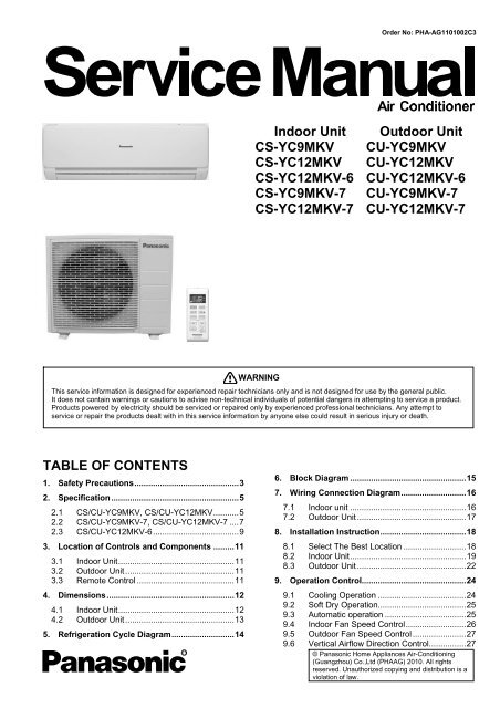
Indoor Unit Outdoor Unit CS-YC9MKV CS-YC12MKV ... - Panasonic
Indoor Unit Outdoor Unit CS-YC9MKV CS-YC12MKV ... - Panasonic
Indoor Unit Outdoor Unit CS-YC9MKV CS-YC12MKV ... - Panasonic

You also want an ePaper? Increase the reach of your titles
YUMPU automatically turns print PDFs into web optimized ePapers that Google loves.
Order No: PHA-AG1101002C3<br />
<strong>Indoor</strong> <strong>Unit</strong><br />
<strong>CS</strong>-<strong>YC9MKV</strong><br />
<strong>CS</strong>-<strong>YC12MKV</strong><br />
<strong>CS</strong>-<strong>YC12MKV</strong>-6<br />
<strong>CS</strong>-<strong>YC9MKV</strong>-7<br />
<strong>CS</strong>-<strong>YC12MKV</strong>-7<br />
<strong>Outdoor</strong> <strong>Unit</strong><br />
CU-<strong>YC9MKV</strong><br />
CU-<strong>YC12MKV</strong><br />
CU-<strong>YC12MKV</strong>-6<br />
CU-<strong>YC9MKV</strong>-7<br />
CU-<strong>YC12MKV</strong>-7<br />
WARNING<br />
This service information is designed for experienced repair technicians only and is not designed for use by the general public.<br />
It does not contain warnings or cautions to advise non-technical individuals of potential dangers in attempting to service a product.<br />
Products powered by electricity should be serviced or repaired only by experienced professional technicians. Any attempt to<br />
service or repair the products dealt with in this service information by anyone else could result in serious injury or death.<br />
TABLE OF CONTENTS<br />
1. Safety Precautions.............................................3<br />
2. Specification.......................................................5<br />
2.1 <strong>CS</strong>/CU-<strong>YC9MKV</strong>, <strong>CS</strong>/CU-<strong>YC12MKV</strong>...........5<br />
2.2 <strong>CS</strong>/CU-<strong>YC9MKV</strong>-7, <strong>CS</strong>/CU-<strong>YC12MKV</strong>-7 ....7<br />
2.3 <strong>CS</strong>/CU-<strong>YC12MKV</strong>-6.....................................9<br />
3. Location of Controls and Components .........11<br />
3.1 <strong>Indoor</strong> <strong>Unit</strong>..................................................11<br />
3.2 <strong>Outdoor</strong> <strong>Unit</strong>...............................................11<br />
3.3 Remote Control ..........................................11<br />
4. Dimensions.......................................................12<br />
4.1 <strong>Indoor</strong> <strong>Unit</strong>..................................................12<br />
4.2 <strong>Outdoor</strong> <strong>Unit</strong>...............................................13<br />
5. Refrigeration Cycle Diagram...........................14<br />
6. Block Diagram ..................................................15<br />
7. Wiring Connection Diagram............................16<br />
7.1 <strong>Indoor</strong> unit ..................................................16<br />
7.2 <strong>Outdoor</strong> <strong>Unit</strong>...............................................17<br />
8. Installation Instruction.....................................18<br />
8.1 Select The Best Location ...........................18<br />
8.2 <strong>Indoor</strong> <strong>Unit</strong>..................................................19<br />
8.3 <strong>Outdoor</strong> <strong>Unit</strong>...............................................22<br />
9. Operation Control.............................................24<br />
9.1 Cooling Operation ......................................24<br />
9.2 Soft Dry Operation......................................25<br />
9.3 Automatic operation ...................................25<br />
9.4 <strong>Indoor</strong> Fan Speed Control..........................26<br />
9.5 <strong>Outdoor</strong> Fan Speed Control .......................27<br />
9.6 Vertical Airflow Direction Control................27<br />
© <strong>Panasonic</strong> Home Appliances Air-Conditioning<br />
(Guangzhou) Co.,Ltd (PHAAG) 2010. All rights<br />
reserved. Unauthorized copying and distribution is a<br />
violation of law.
9.7 Horizontal Airflow Direction Control............27<br />
9.8 Timer Control..............................................27<br />
9.9 Random Auto Restart Control ....................27<br />
10. Protection Control............................................28<br />
10.1 Restart Control (Time Delay Safety Control)<br />
28<br />
10.2 7 minutes Time Save Control .....................28<br />
10.3 60 seconds Forced Operation ....................28<br />
10.4 30 Seconds Forced Operation ...................28<br />
10.5 Anti-Freezing Control .................................28<br />
10.6 Compressor Reverse Rotation Protection<br />
Control...................................................................28<br />
10.7 Dew Prevention Control .............................29<br />
11. Servicing Mode.................................................30<br />
11.1 Auto Off/On Button .....................................30<br />
11.2 Remote Control Button...............................30<br />
12. Troubleshooting Guide....................................31<br />
12.1 Refrigeration Cycle System........................31<br />
Diagnosis methods of a malfunction of a<br />
compressor .............................................................32<br />
13. Disassembly and Assembly Instructions ......33<br />
14. Exploded View and Replacement Pars List...36<br />
14.1 <strong>Indoor</strong> <strong>Unit</strong> ..................................................36<br />
14.2 <strong>Outdoor</strong> <strong>Unit</strong> ...............................................39<br />
2
1. Safety Precautions<br />
• Read the following “SAFETY PRECAUTIONS” carefully before perform any servicing.<br />
• Electrical work must be installed or serviced by a licensed electrician. Be sure to use the correct rating of the<br />
power plug and main circuit for the model installed.<br />
• The caution items stated here must be followed because these important contents are related to safety. The<br />
meaning of each indication used is as below. Incorrect installation or servicing due to ignoring of the instruction<br />
will cause harm or damage, and the seriousness is classified by the following indications.<br />
WARNING<br />
CAUTION<br />
This indication shows the possibility of causing death or serious injury<br />
This indication shows the possibility of causing injury or damage to properties.<br />
• The items to be followed are classified by the symbols:<br />
Symbol with white background denotes item that is PROHIBITED from doing.<br />
Symbol with dark background denotes item that must be carried out.<br />
• Carry out test run to confirm that no abnormality occurs after the servicing. Then, explain to user the operation,<br />
care and maintenance as stated in instructions. Please remind the customer to keep the operating instructions for<br />
future reference.<br />
WARNING<br />
1. Engage dealer or specialist for installation. If installation done by the user is defective, it will cause water leakage,<br />
electrical shock or fire.<br />
2. Install according to this installation instructions strictly. If installation is defective, it will cause water leakage, electrical<br />
shock or fire.<br />
3. Use the attached accessories parts and specified parts for installation. Otherwise, it will cause the set to fall, water<br />
leakage, fire or electrical shock.<br />
4. Install at a strong and firm location which is able to withstand the set’s weight. If the strength is not enough or<br />
installation is not properly done, the set will drop and cause injury.<br />
5. Do not install outdoor unit near handrail of veranda. When installing air-conditioner unit at veranda of high rise<br />
building, child may climb up to outdoor unit and cross over the handrail and causing accident.<br />
6. For electrical work, follow the local national wiring standard, regulation and this installation instruction. An independent<br />
circuit and single outlet must be used. If electrical circuit capacity is not enough or defect found in electrical work, it will<br />
cause electrical shock or fire.<br />
7. This equipment is strongly recommended to be installed with Earth Leakage Circuit Breaker (ELCB) or Residual<br />
Current Device (RCD). Otherwise, it may cause electrical shock and fire in case equipment breakdown or insulation<br />
breakdown.<br />
8. This equipment must be properly earthed. Earth line must not be connected to gas pipe, water pipe, earth of lightning<br />
rod and telephone. Otherwise, it may cause electrical shock in case equipment breakdown or insulation breakdown.<br />
9. Do not use joint cable for indoor/outdoor connection cable. Use the specified <strong>Indoor</strong>/<strong>Outdoor</strong> connection cable, refer<br />
to installation instructions CONNECT THE CABLE TO THE INDOOR UNIT and connect tightly for indoor / outdoor<br />
connection. Clamp the cable so that no external force will be acted on the terminal. If connection or fixing is not<br />
perfect, it will cause heat up or fire at the connection.<br />
10. Wire routing must be properly arranged so that control board cover is fixed properly. If control board cover is not fixed<br />
perfectly, it will cause fire or electrical shock.<br />
11. When carrying out piping connection, take care not to let air substances other than the specified refrigerant go into<br />
refrigeration cycle. Otherwise, it will cause lower capacity, abnormal high pressure in the refrigeration cycle, explosion<br />
and injury.<br />
12. Do not use unspecified cord, modified cord, joint cord or extension cord for power supply cord. Do not share the single<br />
outlet with other appliances. Poor contact, poor insulation or over current will cause electrical shock or fire.<br />
13. During installation, install the refrigerant piping properly before run the compressor. Operation of compressor without<br />
fixing refrigeration piping and valves at opened condition will cause suck-in of air, abnormal high pressure in<br />
refrigeration cycle and result in explosion, injury etc.<br />
14. During pump down operation, stop the compressor before remove the refrigeration piping. Removal of refrigeration<br />
piping while compressor is operating and valves are opened will cause suck-in of air, abnormal high pressure in<br />
refrigeration cycle and result in explosion, injury etc.<br />
15. After completion of installation or service, confirm there is no leakage of refrigerant gas. It may generate toxic gas<br />
when the refrigerant contacts with fire.<br />
16. Ventilate if there is refrigerant gas leakage during operation. It may cause toxic gas when the refrigerant contacts with<br />
fire.<br />
3
17. Recommended installation height for indoor unit shall be at least 2.5 m.<br />
18. The appliance shall be installed in accordance with national wiring regulations.<br />
19. Keep away from small children, the thin film may cling to nose and mouth and prevent breathing.<br />
20. Tighten the flare nut with torque wrench according to specified method. If the flare nut is over-tightened, after a long<br />
period, the flare may break and cause refrigerant gas leakage.<br />
22. Do not insert your fingers or other objects into the unit, high speed rotating fan may cause injury.<br />
23. Do not modify the machine, part, material during repairing service.<br />
24. Must not use other parts except original parts describe in catalog and manual.<br />
CAUTION<br />
1. Do not install the unit at place where leakage of flammable gas may occur. In case gas leaks and accumulates at<br />
surrounding of the unit, it may cause fire.<br />
2. Carry out drainage piping as mentioned in installation instructions. If drainage is not perfect, water may enter the room<br />
and damage the furniture.<br />
3. Do not touch outdoor unit air inlet and aluminums fin. It may cause injury.<br />
4. Select an installation location which is easy for maintenance.<br />
5. Power supply connection to the air conditioner.<br />
Connect the power supply cord of the air conditioner to the mains using one of the following methods.<br />
Power supply point should be in easily accessible place for power disconnection in case of emergency.<br />
In some countries, permanent connection of this air conditioner to the power supply is prohibited.<br />
1) Power supply connection to the receptacle using a power plug.<br />
Use an approved 15/16A power plug with earth pin for the connection to the receptacle.<br />
2) Power supply connection to a circuit breaker for the permanent connection. Use an approved 16A circuit breaker for<br />
the permanent connection. It must be a double pole switch with a minimum 3.5 mm contact gap.<br />
6. Do not release refrigerant.<br />
Do not release refrigerant during piping work for installation, re-installation and during repairing a refrigeration parts.<br />
Take care of the liquid refrigerant, it may cause frostbite.<br />
7. Installation or servicing work.<br />
It may need two people to carry out the installation and service work.<br />
8. Do not install this appliance in a laundry room or other location where water may drip from the ceiling, etc.<br />
9. Do not sit ot step on the unit, you may fall down accidentally.<br />
10. Do not touch the sharp aluminium fin, sharp parts may cause injury.<br />
11. Thermal fuse specification for indoor unit: 250V 3.15A T3.15AL.<br />
4
2. Specification<br />
2.1 <strong>CS</strong>/CU-<strong>YC9MKV</strong>, <strong>CS</strong>/CU-<strong>YC12MKV</strong><br />
Model<br />
Power Supply<br />
Capacity<br />
<strong>Indoor</strong> <strong>CS</strong>-<strong>YC9MKV</strong> <strong>CS</strong>-<strong>YC12MKV</strong><br />
<strong>Outdoor</strong> CU-<strong>YC9MKV</strong> CU-<strong>YC12MKV</strong><br />
Phase, Hz Single, 60 Single, 60<br />
V 220 220<br />
kW 2.64 3.52<br />
BTU/h 9000 12000<br />
Cooling<br />
kJ/h 2270 3027<br />
Running Current A 4.30 5.50<br />
Input Power W 900 1180<br />
EER<br />
W/W 2.93 2.98<br />
Btu/hW 10.00 10.17<br />
Power Factor % 95 97<br />
<strong>Indoor</strong> Noise (H / L ) dB-A 37 / 30 / 39 / 33 /<br />
<strong>Outdoor</strong> Noise (H / L) dB-A 49 / - 49 / -<br />
Max Current (A) / Max Input Power (W) 5.90 / 1.130k 7.40 / 1.450k<br />
Starting Current (A) 25.0 34.0<br />
Type Hermetic Motor Hermetic Motor<br />
Compressor Motor Type Induction (2 poles) Induction (2 poles)<br />
Output Power W 750 1.100k<br />
Type Cross-flow fan Cross-flow fan<br />
Material AS AS<br />
Motor Type Induction (4 poles) Induction (4 poles)<br />
Input Power W - -<br />
Output Power W 20 20<br />
Lo rpm 780 850<br />
Me rpm 880 960<br />
Hi rpm 1010 1060<br />
<strong>Indoor</strong> Fan<br />
Type Propeller Propeller<br />
Material PP PP<br />
Motor Type Induction (6 poles) Induction (6 poles)<br />
Input Power W - -<br />
Output Power W 28 28<br />
Speed Hi rpm 840 880<br />
Moisture Removal L/h (Pt/h) 1.5 (2.6) 2.0 (3.4)<br />
Lo m 3 /min (ft 3 /m) 8.9 (315) 9.8 (347)<br />
<strong>Indoor</strong> Airflow Me m 3 /min (ft 3 /m) 10.1 (355) 11.6 (392)<br />
Hi m 3 /min (ft 3 /m) 11.6 (408) 12.3 (433)<br />
<strong>Outdoor</strong><br />
Airflow<br />
Hi m 3 /min (ft 3 /m) 26.8 (948) 26.8 (948)<br />
<strong>Outdoor</strong> Fan<br />
Refrigeration<br />
Cycle<br />
Dimension<br />
Control Device Capillary Tube Capillary Tube<br />
Refrigerant Oil cm 3 ATMOS M60 OR SUNISO 4GDID<br />
ATMOS NM56 OR SUNISO 4GDID (350)<br />
(290)<br />
Refrigerant<br />
g (oz) R22, 550 (19.3) R22, 820 (28.9)<br />
Type<br />
Height(I/D /<br />
mm (inch) 283 (11-5/32) 530(20-7/8) 283 (11-5/32) 530 (20-7/8)<br />
O/D)<br />
Width (I/D / O/D) mm (inch) 803 (31-5/8) 650(25-19/32) 803 (31-5/8) 650 (25-19/32)<br />
Depth (I/D /<br />
mm (inch) 214 (8-7/16) 230 (9-1/16) 214 (8-7/16) 230 (9-1/16)<br />
O/D)<br />
5
Weight Net (I/D / O/D) kg (lb) 8.0 (18) 21 (46) 8.0 (18) 26 (57)<br />
Piping<br />
Pipe Diameter (Liquid /<br />
Gas)<br />
mm (inch) 6.35 (1/4) / 9.52 (3/8) 6.35 (1/4) / 12.70 (1/2)<br />
Standard length m (ft) 5.0 (16.4) 5.0 (16.4)<br />
Length range (min – max) m (ft) 3 (9.8) ~15 (49.2) 3 (9.8) ~ 15(49.2)<br />
I/D & O/D Height different m (ft) 5.0 (16.4) 5.0 (16.4)<br />
Additional Gas Amount g/m (oz/ft) 20 (0.2) 20 (0.2)<br />
Length for Additional Gas m (ft) 5.0 (16.4) 5.0 (16.4)<br />
Drain Hose<br />
Inner Diameter mm 16 16<br />
Length mm 500 500<br />
Fin Material Pre coated Pre coated<br />
<strong>Indoor</strong> Heat<br />
Exchanger<br />
<strong>Outdoor</strong><br />
Heat<br />
Exchanger<br />
Air Filter<br />
Fin Type Slit Fin Slit Fin<br />
Row x Stage x<br />
FPI<br />
2 x 16 x 19 2 x 16 x 19<br />
Size (W x H x L) mm 610 x 336 x 25.4 610 x 315 x 25.4<br />
Fin Material Bear Fin Bear Fin<br />
Fin Type Slit Fin Slit Fin<br />
Row x Stage x<br />
FPI<br />
1 x 24 x 18 2 x 24 x 18<br />
Size (W x H xD) mm 570.7 x504.0 x 12.7 565.2(545.3) x 504.0 x 12.7<br />
Material P.P.HONEY COMB P.P.HONEY COMB<br />
Type One-touch One-touch<br />
Power Supply <strong>Indoor</strong> <strong>Indoor</strong><br />
Power Supply Cord A 10 10<br />
Thermostat - -<br />
Protection Device - -<br />
<strong>Indoor</strong> Operation Range<br />
DRY BULB WET BULB DRY BULB WET BULB<br />
Maximum 32 23 32 23<br />
Minimum 16 11 16 11<br />
<strong>Outdoor</strong> Operation Range<br />
Maximum 43 26 43 26<br />
Minimum 16 11 16 11<br />
1. Cooling capacities are based on indoor temperature of 27°C DRY BULB (80.6°F DRY BULB), 19.0°C WET BULB (66°F WET BULB) and<br />
outdoor air temperature of 35°C DRY BULB (95°F DRY BULB), 24°C WET BULB (75.2°F WET BULB)<br />
6
2.2 <strong>CS</strong>/CU-<strong>YC9MKV</strong>-7, <strong>CS</strong>/CU-<strong>YC12MKV</strong>-7<br />
Cooling<br />
Model<br />
Power Supply<br />
Capacity<br />
<strong>Indoor</strong> <strong>CS</strong>-<strong>YC9MKV</strong>-7 <strong>CS</strong>-<strong>YC12MKV</strong>-7<br />
<strong>Outdoor</strong> CU-<strong>YC9MKV</strong>-7 CU-<strong>YC12MKV</strong>-7<br />
Phase, Hz Single, 60 Single, 60<br />
V 220 220<br />
kW 2.64 3.52<br />
BTU/h 9000 12000<br />
kJ/h 2270 3027<br />
Running Current A 4.30 5.50<br />
Input Power W 900 1180<br />
EER<br />
W/W 2.93 2.98<br />
Btu/hW 10.00 10.17<br />
Power Factor % 95 97<br />
<strong>Indoor</strong> Noise (H / L ) dB-A 37 / 30 / 39 / 33 /<br />
<strong>Outdoor</strong> Noise (H / L) dB-A 49 / - 49 / -<br />
Max Current (A) / Max Input Power (W) 5.90 / 1.130k 7.40 / 1.450k<br />
Starting Current (A) 25.0 34.0<br />
Type Hermetic Motor Hermetic Motor<br />
Compressor Motor Type Induction (2 poles) Induction (2 poles)<br />
Output Power W 750 1.100k<br />
Type Cross-flow fan Cross-flow fan<br />
Material AS AS<br />
Motor Type Induction (4 poles) Induction (4 poles)<br />
Input Power W - -<br />
Output Power W 20 20<br />
Lo rpm 780 850<br />
Me rpm 880 960<br />
Hi rpm 1010 1060<br />
Type Propeller Propeller<br />
Material PP PP<br />
Motor Type Induction (6 poles) Induction (6 poles)<br />
Input Power W - -<br />
Output Power W 28 28<br />
Speed Hi rpm 840 880<br />
Moisture Removal L/h (Pt/h) 1.5 (2.6) 2.0 (3.4)<br />
Lo m 3 /min (ft 3 /m) 8.9 (315) 9.8 (347)<br />
<strong>Indoor</strong> Airflow Me m 3 /min (ft 3 /m) 10.1 (355) 11.6 (392)<br />
Hi m 3 /min (ft 3 /m) 11.6 (408) 12.3 (433)<br />
<strong>Outdoor</strong><br />
Airflow<br />
Hi m 3 /min (ft 3 /m) 26.8 (948) 26.8 (948)<br />
<strong>Indoor</strong> Fan<br />
<strong>Outdoor</strong> Fan<br />
Refrigeration<br />
Cycle<br />
Dimension<br />
Control Device Capillary Tube Capillary Tube<br />
Refrigerant Oil cm 3 ATMOS M60 OR SUNISO 4GDID<br />
ATMOS NM56 OR SUNISO 4GDID (350)<br />
(290)<br />
Refrigerant<br />
g (oz) R22, 550 (19.3) R22, 820 (28.9)<br />
Type<br />
Height(I/D /<br />
mm (inch) 283 (11-5/32) 530(20-7/8) 283 (11-5/32) 530 (20-7/8)<br />
O/D)<br />
Width (I/D / O/D) mm (inch) 803 (31-5/8) 650(25-19/32) 803 (31-5/8) 650 (25-19/32)<br />
Depth (I/D /<br />
mm (inch) 214 (8-7/16) 230 (9-1/16) 214 (8-7/16) 230 (9-1/16)<br />
O/D)<br />
7
Weight Net (I/D / O/D) kg (lb) 8.0 (18) 21 (46) 8.0 (18) 26 (57)<br />
Piping<br />
Pipe Diameter (Liquid /<br />
Gas)<br />
mm (inch) 6.35 (1/4) / 9.52 (3/8) 6.35 (1/4) / 12.70 (1/2)<br />
Standard length m (ft) 5.0 (16.4) 5.0 (16.4)<br />
Length range (min – max) m (ft) 3 (9.8) ~15 (49.2) 3 (9.8) ~ 15(49.2)<br />
I/D & O/D Height different m (ft) 5.0 (16.4) 5.0 (16.4)<br />
Additional Gas Amount g/m (oz/ft) 20 (0.2) 20 (0.2)<br />
Length for Additional Gas m (ft) 5.0 (16.4) 5.0 (16.4)<br />
Drain Hose<br />
Inner Diameter mm 16 16<br />
Length mm 500 500<br />
Fin Material Pre coated Pre coated<br />
<strong>Indoor</strong> Heat<br />
Exchanger<br />
<strong>Outdoor</strong><br />
Heat<br />
Exchanger<br />
Air Filter<br />
Fin Type Slit Fin Slit Fin<br />
Row x Stage x<br />
FPI<br />
2 x 16 x 19 2 x 16 x 19<br />
Size (W x H x L) mm 610 x 336 x 25.4 610 x 315 x 25.4<br />
Fin Material Bear Fin Bear Fin<br />
Fin Type Slit Fin Slit Fin<br />
Row x Stage x<br />
FPI<br />
1 x 24 x 18 2 x 24 x 18<br />
Size (W x H xD) mm 570.7 x504.0 x 12.7 565.2(545.3) x 504.0 x 12.7<br />
Material P.P.HONEY COMB P.P.HONEY COMB<br />
Type One-touch One-touch<br />
Power Supply <strong>Indoor</strong> <strong>Indoor</strong><br />
Power Supply Cord A 10 10<br />
Thermostat - -<br />
Protection Device - -<br />
<strong>Indoor</strong> Operation Range<br />
DRY BULB WET BULB DRY BULB WET BULB<br />
Maximum 32 23 32 23<br />
Minimum 16 11 16 11<br />
<strong>Outdoor</strong> Operation Range<br />
Maximum 43 26 43 26<br />
Minimum 16 11 16 11<br />
2. Cooling capacities are based on indoor temperature of 27°C DRY BULB (80.6°F DRY BULB), 19.0°C WET BULB (66°F WET BULB) and<br />
outdoor air temperature of 35°C DRY BULB (95°F DRY BULB), 24°C WET BULB (75.2°F WET BULB)<br />
8
2.3 <strong>CS</strong>/CU-<strong>YC12MKV</strong>-6<br />
Cooling<br />
Model<br />
Power Supply<br />
<strong>Indoor</strong><br />
<strong>Outdoor</strong><br />
<strong>CS</strong>-<strong>YC12MKV</strong>-6<br />
CU-<strong>YC12MKV</strong>-6<br />
Phase, Hz Single, 60<br />
V 220<br />
kW 3.52<br />
Capacity<br />
BTU/h 12000<br />
kJ/h 3027<br />
Running Current A 5.50<br />
Input Power W 1180<br />
EER<br />
W/W 2.98<br />
Btu/hW 10.17<br />
Power Factor % 97<br />
<strong>Indoor</strong> Noise (H / L / QLo) dB-A 39 / 33 / -<br />
<strong>Outdoor</strong> Noise (H / L) dB-A 49 / -<br />
Max Current (A) / Max Input Power (W) 7.40 / 1.450k<br />
Starting Current (A) 34.0<br />
Type<br />
Hermetic Motor<br />
Compressor Motor Type<br />
Induction (2 poles)<br />
Output Power W 1100<br />
Type<br />
Cross-flow fan<br />
Material<br />
AS<br />
Motor Type<br />
Induction (4-poles)<br />
Input Power W -<br />
Output Power W 20<br />
Lo rpm 850<br />
<strong>Indoor</strong><br />
Airflow<br />
Me rpm 960<br />
Hi rpm 1060<br />
<strong>Indoor</strong> Fan<br />
<strong>Outdoor</strong> Fan<br />
Type<br />
Material<br />
Motor Type<br />
Propeller<br />
PP<br />
Induction (6 poles)<br />
Input Power W -<br />
Output Power W 28<br />
Speed Hi rpm 880<br />
Moisture Removal L/h (Pt/h) 2.0 (3.4)<br />
<strong>Indoor</strong> Airflow<br />
<strong>Outdoor</strong><br />
Airflow<br />
Refrigeration<br />
Cycle<br />
Lo<br />
Me<br />
Hi<br />
Hi<br />
Control Device<br />
m 3 /min<br />
(ft 3 /m)<br />
m 3 /min<br />
(ft 3 /m)<br />
m 3 /min<br />
(ft 3 /m)<br />
m 3 /min<br />
(ft 3 /m)<br />
9.8 (347)<br />
11.6 (392)<br />
12.3 (433)<br />
26.8 (948)<br />
Capillary tube<br />
Refrigerant Oil cm 3 ATMOS NM56 OR SUNISO 4GDID (350)<br />
Refrigerant Type g (oz) R22, 820 (28.9)<br />
9
Height(I/D / O/D) mm (inch) 283 (11-5/32) 530 (20-7/8)<br />
Dimension Width (I/D / O/D) mm (inch) 803 (31-5/8) 650 (25-19/32)<br />
Depth (I/D / O/D) mm (inch) 214 (8-7/16) 230 (9-1/16)<br />
Weight Net (I/D / O/D) kg (lb) 8.0 (18) 26 (57)<br />
Pipe Diameter (Liquid / Gas) mm (inch) 6.35 (1/4) / 12.70 (1/2)<br />
Piping<br />
Standard length m (ft) 5.0 (16.4)<br />
Length range (min – max) m (ft) 3 (9.8) ~ 15(49.2)<br />
I/D & O/D Height different m (ft) 5.0 (16.4)<br />
Additional Gas Amount g/m (oz/ft) 20 (0.2)<br />
Length for Additional Gas m (ft) 5.0 (16.4)<br />
Drain Hose<br />
<strong>Indoor</strong> Heat<br />
Exchanger<br />
<strong>Outdoor</strong><br />
Heat<br />
Exchanger<br />
Air Filter<br />
Inner Diameter mm 16<br />
Length mm 500<br />
Fin Material<br />
Fin Type<br />
Pre coated<br />
Slit fin<br />
Row x Stage x FPI 2 x 16 x 19<br />
Size (W x H x L) mm 610 x 315 x 25.4<br />
Fin Material<br />
Bear Fin<br />
Fin Type<br />
Slit Fin<br />
Row x Stage x FPI 2 x 24 x 18<br />
Size (W x H x L) mm 565.2(545.3) x 504.0 x 12.7<br />
Material<br />
Type<br />
Power Supply<br />
P.P.HONEY COMB<br />
One-touch<br />
Power Supply Cord A 10<br />
Thermostat -<br />
Protection Device -<br />
<strong>Indoor</strong> Operation Range<br />
DRY BULB<br />
<strong>Indoor</strong><br />
WET BULB<br />
Maximum 32 23<br />
Minimum 16 11<br />
<strong>Outdoor</strong> Operation Range<br />
Maximum 43 26<br />
Minimum 16 11<br />
1. Cooling capacities are based on indoor temperature of 27°C DRY BULB (80.6°F DRY BULB), 19.0°C WET BULB (66°F WET BULB) and<br />
outdoor air temperature of 35°C DRY BULB (95°F DRY BULB), 24°C WET BULB (75.2°F WET BULB)<br />
10
3. Location of Controls and Components<br />
3.1 <strong>Indoor</strong> <strong>Unit</strong><br />
3.2 <strong>Outdoor</strong> <strong>Unit</strong><br />
3.3 Remote Control<br />
11
4. Dimensions<br />
4.1 <strong>Indoor</strong> <strong>Unit</strong><br />
<strong>Unit</strong> : mm<br />
12
4.2 <strong>Outdoor</strong> <strong>Unit</strong><br />
13
5. Refrigeration Cycle Diagram<br />
Evaporator<br />
Condenser<br />
14
6. Block Diagram<br />
POWER SUPPLY AC 220v, 60 Hz, SINGLE PHASE,<br />
15
7. Wiring Connection Diagram<br />
7.1 <strong>Indoor</strong> unit<br />
16
7.2 <strong>Outdoor</strong> <strong>Unit</strong><br />
17
8. Installation Instruction<br />
8.1 Select The Best Location<br />
8.1.3 <strong>Indoor</strong>/<strong>Outdoor</strong> <strong>Unit</strong><br />
8.1.1 <strong>Indoor</strong> <strong>Unit</strong><br />
• There should not be any heat source or steam near the<br />
unit.<br />
• There should not be any obstacles blocking the air<br />
circulation.<br />
• A place where air circulation in the room is good.<br />
• A place where drainage can be easily done.<br />
• A place where noise prevention is taken into consideration.<br />
• Do not install the unit near the door way.<br />
• Ensure the spaces indicated by arrows from the wall,<br />
ceiling, fence or other obstacles.<br />
• Recommended installation height for indoor unit shall be at<br />
least 2.5m.<br />
8.1.2 <strong>Outdoor</strong> <strong>Unit</strong><br />
• If an awning is built over the unit to prevent direct sunlight<br />
or rain, be careful that heat radiation from the condenser is<br />
not obstructed.<br />
• There should not be any animal or plant which could be<br />
affected by hot air discharged.<br />
• Keep the spaces indicated by arrows from wall, ceiling,<br />
fence or other obstacles.<br />
• Do not place any obstacles which may cause a short circuit<br />
of the discharged air.<br />
• If piping length is over the rated length, additional<br />
refrigerant should be added as shown in the table below:<br />
Model<br />
<strong>CS</strong>/CU-<strong>YC9MKV</strong><br />
<strong>CS</strong>/CU-<strong>YC9MKV</strong>-7<br />
<strong>CS</strong>/CU-<strong>YC12MKV</strong><br />
<strong>CS</strong>/CU-<strong>YC12MKV</strong>-6<br />
<strong>CS</strong>/CU-<strong>YC12MKV</strong>-7<br />
Piping size<br />
Gas Liquid<br />
Rated Max Min<br />
Length Elevati Piping<br />
(m) on (m) Length<br />
(m)<br />
Example:<br />
If the unit is installed at a 10m distance, the quantity<br />
of additional refrigerant should be 60 g.<br />
…… (10-5) m x 20g/m = 100 g<br />
Max Additional<br />
Piping Refrigera<br />
Length nt (g/m)<br />
(m)<br />
3/8” 1/4" 5 5 3 15 20<br />
1/2” 1/4” 5 5 3 15 20<br />
*This illustration is for explanation<br />
purposes only.<br />
The indoor unit will actually face a<br />
different way.<br />
18
8.2 <strong>Indoor</strong> <strong>Unit</strong><br />
8.2.1 How to Fix Installation Plate<br />
The mounting wall is strong and solid enough to prevent if from the vibration.<br />
The centre of installation plate should be at more<br />
than 450 mm at right and left of the wall.<br />
The distance from installation plate edge to<br />
ceiling should more than 120 mm.<br />
From installation plate left edge to unit’s left side<br />
is 170 mm.<br />
From installation plate right edge to unit’s right<br />
side is 160 mm.<br />
○B<br />
: For left side piping, piping connection for gas should be about 105 mm from this line.<br />
: For left side piping, piping connection cable should be about 154 mm from this line.<br />
1 Mount the installation plate on the wall with 5 screws or more. (If mounting the unit on the wall, consider<br />
using anchor bolts.) Always mount the installation plate horizontally by aligning the marking-off line with<br />
the thread and using a level gauge.<br />
2 Drill the piping plate hole with ø70 mm hole-core drill.<br />
• Put measuring tape at position as shown in the diagram above. The hole centre is<br />
obtained by measuring the distance namely 178.5 mm and 161 mm for left and right<br />
hole respectively.<br />
• Drill the piping plate hole at either the right or left and the hole should be slightly slanted<br />
to the outdoor side.<br />
8.2.2 To Drill a Hole in the Wall and Install a Sleeve of<br />
Piping<br />
1 Insert the piping sleeve to the hole.<br />
2 Fix the busing to the sleeve.<br />
3 Cut the sleeve until it extrudes about 15mm from the wall<br />
Caution<br />
When the wall is hollow, please be sure to use the sleeve for tube<br />
ass’y to prevent dangers caused by mice biting the connecting<br />
cable.<br />
<strong>Indoor</strong><br />
Sleeve for<br />
tube ass’y<br />
Wall<br />
<strong>Outdoor</strong><br />
15 mm<br />
Approx. 5 - 7 mm<br />
Bushing for tube ass’y<br />
4 Finish by sealing the sleeve with putty or caulking compound at the final<br />
stage.<br />
Ø 70 through hole<br />
Putty or caulking compound<br />
19
8.2.3 <strong>Indoor</strong> <strong>Unit</strong> Installation<br />
20
8.2.4 Connect the Cable to the <strong>Indoor</strong> <strong>Unit</strong><br />
1 The inside and outside connecting cable can be connected without removing the front grille.<br />
2 Connecting cable between indoor unit and outdoor unit shall be approved polychloroprene sheathed 3x 1.0<br />
mm 2 .( <strong>YC9MKV</strong>,<strong>YC9MKV</strong>-7) or 3 x 1.5mm 2 (<strong>YC12MKV</strong>, <strong>YC12MKV</strong>-6, <strong>YC12MKV</strong>-7) flexible cords, type<br />
designation 245 IEC 57 or heavier cord.<br />
Ensure the color of wires of outdoor unit and the terminal numbers are the same to the indoor’s<br />
respectively.<br />
Earth lead wire shall be longer than the other lead wires as shown in the figure for the electrical safety<br />
in case of the slipping out of the cord from the anchorage.<br />
<br />
Secure the cable onto the board with the holder (clamper).<br />
8.2.4.1 Wiring Stripping and connecting requirement<br />
10 ± 1 mm<br />
Wire stripping<br />
No loose strand when insert<br />
<strong>Indoor</strong>/outdoor<br />
connecting<br />
terminal board<br />
5 mm<br />
or more<br />
(gap between<br />
wires)<br />
Conductor<br />
fully insert<br />
ACCEPT<br />
Conductor<br />
over insert<br />
PROHIBITED<br />
Conductor not<br />
fully insert<br />
PROHIBITED<br />
8.2.5 Cutting and flaring the piping<br />
1 Please cut using pipe cutter and then remove the burrs.<br />
2 Remove the burrs by using reamer. If burrs are not removed, gas leakage may be caused. Turn the piping<br />
end down to avoid the metal powder entering the pipe.<br />
3 Please make flare after inserting the flare nut onto the copper pipes.<br />
1. To cut<br />
Point down<br />
Pipe<br />
Reamer<br />
2. To remove burrs<br />
Bar<br />
Clamp handle<br />
Handle<br />
3. To flare<br />
Yoke<br />
Core<br />
Red arrow mark<br />
Bar<br />
0 – 0.5 mm<br />
Copper pipe<br />
Improper flaring<br />
Inclined S urface Cracked U neven<br />
dam aged thickness<br />
When properly flared, the internal surface of the<br />
flare will evenly shine and be of even thickness.<br />
Since the flare part comes into contact with the<br />
connections, carefully check the flare finish.<br />
21
8.3 <strong>Outdoor</strong> <strong>Unit</strong><br />
8.3.1 Install the <strong>Outdoor</strong> <strong>Unit</strong><br />
• After selecting the best location, start installation according to indoor/outdoor unit installation diagram.<br />
1 Fix the unit on concrete or rigid frame firmly and horizontally by bolt nut (ø10 mm).<br />
2 When installing at roof, please consider strong wind and earthquake.<br />
Please fasten the installation stand firmly with bolt or nails.<br />
A B<br />
C<br />
A B C D<br />
474 86.7 19.9 261<br />
D<br />
8.3.2 Connecting the Piping<br />
8.3.2.1 Connecting the piping to indoor unit<br />
Please make flare after inserting flare nut (locate at joint portion, of tube assembly) onto the copper pipe. (In case of<br />
using long piping)<br />
Connect the piping<br />
• Align the center of piping and sufficiently tighten the flare nut with fingers.<br />
• Further tighten the flare nut with torque wrench in specified torque as stated in the table.<br />
8.3.2.2 Connecting the piping to outdoor unit<br />
Decide piping length and then cut by using pipe cutter. Remove burrs from cut edge. Make flare after inserting the<br />
flare nut (locate at valve) onto the copper pipe. Align center of piping to valves and then tighten with torque wrench to<br />
the specified torque as stated in the table.<br />
Model<br />
Piping size (Torque)<br />
Gas<br />
Liquid<br />
<strong>YC9MKV</strong>, 3/8" (42N•m ) 1/4" (18N•m)<br />
Spanner<br />
or Wrench<br />
Torque<br />
wrench<br />
<strong>YC9MKV</strong>-7<br />
<strong>YC12MKV</strong>.<br />
<strong>YC12MKV</strong>-6<br />
<strong>YC12MKV</strong>-7<br />
1/2" (55N•m) 1/4" (18N•m)<br />
Do not over tighten, over tightening<br />
cause gas leakage<br />
8.3.3 Evacuation of the equipment<br />
When installing an air conditioner, be sure to evacuate the air inside the indoor unit and pipes in the following<br />
procedures.<br />
22
1 Connect a charging hose with a push pin to the Low side of a charging set and the service port of the 3-way<br />
valve.<br />
• Be sure to connect the end of the charging hose with the push pin to the service port.<br />
2 Connect the center hose of the charging set to a vacuum pump.<br />
3 Turn on the power switch of the vacuum pump and make sure that the needle in the gauge moves from<br />
0cmHg (0 Mpa) to -76cmHg (-0.1Mpa). Then evacuate the air approximately ten minutes.<br />
4 Close the Low side valve of the charging set and turn off the vacuum pump. Make sure the needle in the<br />
gauge does not move after approximately five minutes.<br />
Note: BE SURE TO TAKE THIS PROCEDURE IN ORDER TO AVOID REFRIGERANT GAS LEAKAGE.<br />
5 Disconnect the charging hose from the vacuum pump and from the service port of the 3-way valve.<br />
6 Tighten the service port caps of the 3-way valve at a torque of 18N•m with a torque wrench.<br />
7 Remove the valve caps of both of the 2-way valve and 3-way valve. Position both of the valves to “OPEN”<br />
using a hexagonal wrench (4mm).<br />
8 Mount valve caps onto the 2-way valve and the 3-way valve.<br />
• Be sure to check for gas leakage.<br />
Caution<br />
• If gauge needle does not move from 0cmHg (0Mpa) to -76cmHg (-0.1Mpa), in step 3 above take the following<br />
measure:<br />
• If the leak stops when the piping connections are tightened further, continue working from step 3.<br />
• If the leak does not stop when the connections are retightened, repair location of leak.<br />
• Do not release refrigerant during piping work for installation and reinstallation. Take care of the liquid refrigerant,<br />
it may cause frostbite.<br />
8.3.4 Connect the cable to the outdoor unit<br />
1 Remove the control board cover from the unit by loosening the screw.<br />
2 Connecting cable between indoor unit and outdoor unit shall be approved polychloroprene sheathed 3x 1.0<br />
mm 2 . ( <strong>YC9MKV</strong>,<strong>YC9MKV</strong>-7) or 3 x 1.5mm 2 (<strong>YC12MKV</strong>, <strong>YC12MKV</strong>-6, <strong>YC12MKV</strong>-7) flexible cords, type<br />
designation 245 IEC 57 or heavier cord.<br />
3 Secure the cable onto the control board with the holder (clamper).<br />
4 Attach the control board cover back to the original position with the screw.<br />
5 For wiring stripping and connection requirement, refer to instruction 8.2.4.1 of indoor unit.<br />
8.3.5 Piping insulation<br />
1 Please carry insulation at piping connection portion as mentioned in <strong>Indoor</strong>/<strong>Outdoor</strong> <strong>Unit</strong> Installation Diagram.<br />
Please wrap the insulated piping end to prevent water from going inside the piping.<br />
2 If drain hose or connecting piping is in the room (where dew may form), please increase the insulation by<br />
using POLY-E-FOAM with thickness 6mm or above.<br />
23
9. Operation Control<br />
9.1 Cooling Operation<br />
• Cooling Operation can be set using remote control.<br />
• This operation is applied to cool down the room temperature to the setting temperature set on the<br />
remote control.<br />
• The remote control setting temperature, which takes the reading of intake air temperature sensor, can<br />
be adjusted from 16℃ to 30℃<br />
• During cooling operation, the compressor will stop and restart as shown in figure below:<br />
9.1.1 Time Graph for Cooling Operation.<br />
24
9.2 Soft Dry Operation<br />
• Soft Dry Operation can be set using remote control.<br />
• Soft Dry operation is applied to dehumidify and to perform a gentle cooling to the room.<br />
• When selecting Soft Dry operation, the operation will be cooling until the room temperature reaches the set<br />
temperature on remote control, and then soft Dry will be activated.<br />
• The Soft Dry operation runs for less tan 10 minutes and once stop it will not be activated within 6 minutes.<br />
• Dry operation area is shown as follows:-<br />
9.2.1 Time Graph for Soft Dry operation.<br />
9.3 Automatic operation<br />
Automatic operation can be set using remote control.<br />
Operation mode is determined by set temperature of remote control, indoor intake temperature.<br />
This operation starts to operate with indoor fan at SLo speed for 20 seconds to judge the intake air temperature.<br />
After judged the temperature, the operation mode is determined by referring below standard.<br />
25
9.4 <strong>Indoor</strong> Fan Speed Control<br />
<strong>Indoor</strong> fan speed can be set using remote control.<br />
9.4.1 Fan Speed rotation Chart<br />
Model<br />
speed<br />
Hi Me Lo Slo<br />
<strong>CS</strong>-YC9 1080 920 750 500<br />
<strong>CS</strong>-YC12 1140 1000 820 500<br />
9.4.2 Automatic Fan Speed Control<br />
• When set to Auto Fan Speed, the fan speed is adjusted between maximum and minimum setting as shown in<br />
the table.<br />
Shi Hi Me Lo Lo- SLo SSLo<br />
Cooling<br />
Auto o o o<br />
Manual o o o<br />
Soft Dry Auto o o<br />
Area Manual o o<br />
• Auto Fan Speed during cooling operation:-<br />
1. At the beginning of each compressor starts operation, indoor fan speed increases gradually for deodorizing<br />
purpose.<br />
2. <strong>Indoor</strong> fan will rotate alternately between off and on as shown in below diagram.<br />
*1. Fan speed will be at Hi till the compressors ceases when set temperature is reached.<br />
*2. Fan Speed will be at Me when the compressor restarts.<br />
• Auto Fan Speed during soft Dry operation.<br />
1. <strong>Indoor</strong> fan will rotate alternately between OFF and Lo-.<br />
2. At the beginning of each compressor starts operation, indoor fan will increase fan speed gradually for deodorizing<br />
purpose.<br />
26
9.4.3 Manual Fan Speed Control<br />
• Manual fan speed can be set with Fan Speed selection button at the remote control<br />
• There are 3 level of fan speed setting : Lo, Me, Hi<br />
9.5 <strong>Outdoor</strong> Fan Speed Control<br />
• There is only one speed for outdoor fan motor.<br />
• When compressor stops, outdoor fan will continue running for 30 seconds.<br />
9.6 Vertical Airflow Direction Control.<br />
• The louver can be adjusted by pressing the button at remote control to the desired position.<br />
• When operation stops using remote control, the discharge vent is reset ,and stop at the closing position..<br />
Operation mode<br />
Cooling/ Soft Dry<br />
During judgment<br />
Manual 18° 28° 37° 46° 55°<br />
Auto 18° ~ 55°<br />
Manual<br />
Depending on remote control setting<br />
Auto 18°<br />
9.7 Horizontal Airflow Direction Control<br />
• Horizontal airflow direction louver can be adjusted manually by hand.<br />
9.8 Timer Control<br />
• Timer can be set using remote control (12-hour timer setting). When Timer- ON is set for cooling and Soft Dry<br />
operation, the unit with timer set will start operate earlier than the setting time. This is to provide a comfortable<br />
environment when reaching the set ON time.<br />
• For Cooling and Soft Dry operation, the operation will start 15 minutes before the set time.<br />
• For Automatic operation, the indoor fan will operate at Slo speed for 25 seconds, 30 minutes before the set time<br />
to detect the intake air temperature to determine the operation mode. The power LED will blink during detection.<br />
• If main power supply is switched off or encounter power failure, timer setting will be cancel. Timer needs to be<br />
reset.<br />
• The ON timer or OFF timer will be cancel by pressing CANCEL button.<br />
• The ON timer or OFF timer will be cancel is ON/OFF operation button is pressed.<br />
• Each timer setting is effective only once.<br />
9.9 Random Auto Restart Control<br />
• If there is a power failure during operation, the air conditioner will automatically restart after 3 minutes when the<br />
power is resumed.<br />
• It will start with previous operation mode and airflow direction.<br />
• If timer is set, timer setting will be cancel. The timer needs to be reset after the power is resumed.<br />
27
10. Protection Control<br />
10.1 Restart Control (Time Delay Safety Control)<br />
• When the thermo-off temperature is reach during Cooling operation, the compressor stops for 3 minutes<br />
(minimum) before resume operation.<br />
• When the thermo-off temperature is reach during Soft Dry operation, the compressor stops for 6 minutes<br />
(minimum) before resume operation.<br />
• This control is not applicable if the power supply is cut off and on again.<br />
• This phenomenon is to balance the pressure inside the refrigerant cycle.<br />
10.2 7 minutes Time Save Control<br />
• The compressor will automatically operate if it has stopped for 7 minutes even if the room temperature Is not<br />
reached the Thermo-ON point.<br />
• This phenomenon is to prevent the room humidity raising.<br />
10.3 60 seconds Forced Operation<br />
• Once the air conditioner is turned on, the compressor will not stop within 60 seconds in normal operation even if<br />
the intake air temperature has reached the thermo-off point. However, forced stop by pressing the OFF/ON<br />
operation button at the remote control is permitted.<br />
• This phenomenon is to allow the refrigerant oil run in a full cycle and return back to the outdoor unit.<br />
10.4 30 Seconds Forced Operation<br />
• Once the air conditioner is turned on, the compressor will not stop within 30 seconds in a normal operation<br />
although the intake air temperature has reached the thermo-off temperature. However, force stop by pressing the<br />
OFF/ON button at the remote control is permitted or the Auto OFF/ON button at indoor unit.<br />
• The reason for the compressor to force operation for minimum 30 seconds is to allow the refrigerant oil run in a<br />
full cycle and return back to the outdoor unit.<br />
10.5 Anti-Freezing Control<br />
• If the temperature of evaporator is lower than 2℃ continuously for 4 minutes, the compressor will cease to<br />
prevent the evaporator from freezing. Fan Speed setting will not be changed.<br />
• When temperature of evaporator reach 10℃, compressor will restart.<br />
• During Cooling and soft Dry operation, the Time Delay Safety Control will be applied if the recovery time is too<br />
short.<br />
10.6 Compressor Reverse Rotation Protection Control<br />
If the compressor has been continuously running for 5 minutes or longer, and the difference of temperature between<br />
intake air and evaporator is continuously lower than 2.5℃ or below for 2 minutes, the compressor will stop, and then<br />
restart 3 minutes later. (Time Delay Safety Control is effective.)<br />
Compressor runs ≥ 5 min<br />
△T≤ 2.5℃ for 2 min<br />
Compressor stops<br />
Compressor restarts 3 minutes later<br />
△ T= Intake air temperature – <strong>Indoor</strong> heat exchanger temperature<br />
28
10.7 Dew Prevention Control<br />
• To prevent dew formation at indoor unit discharge area, the horizontal air vane is automatically set at position 2<br />
(refer to 9.6).<br />
• This control is activated when:-<br />
*Compressor runs continuously for 60 minutes.<br />
*Horizontal air vane is at position 4 or 5 (refer to 9.6).<br />
*Actual fan speed is lower than Lo level.<br />
*Intake air temperature is lower than 29℃<br />
*Intake air temperature changes within 2℃ for more than 30 minutes.<br />
• Dew prevention stops when:-<br />
• Any of the above condition is out of the range described above.<br />
• Operation stops.<br />
• Power OFF.<br />
29
11. Servicing Mode<br />
11.1 Auto Off/On Button<br />
ON<br />
Auto Operation<br />
5 sec 10 sec 15 sec<br />
Test Run Operation<br />
(Forced Cooling Operation)<br />
Remote Control<br />
Receiving Sound<br />
OFF/ON<br />
Beep Beep x 2 Beep x 3<br />
Random Auto Restart<br />
OFF/ON<br />
1 AUTO OPERATION MODE<br />
Auto Operation will be activated immediately once the Auto OFF/ON button is pressed. This operation can be<br />
used to operate air conditioner with limited function if remote control is misplaced or malfunction.<br />
2 TEST RUN OPERATION (FOR PUMP DOWN/SERVICING PURPOSE)<br />
The Test Run Operation will be activated if the Auto OFF/ON button is pressed continuously for more than 5<br />
seconds. A “beep” sound will be heard at the fifth seconds, in order to identify the starting of this operation.<br />
3 REMOTE CONTROL RECEIVING SOUND OFF/ON MODE<br />
• To switch OFF the remote control receiving sound, press and hold "AUTO OFF/ON"<br />
button for approximately 10 seconds until you hear 2 “beep” sounds. Release you hand<br />
and then press this button again for 10 seconds until you hear 2 “beep” sounds again,<br />
setting complete.<br />
• To switch ON the sounds, repeat above operation.<br />
4 Random Auto Restart Function OFF/ON<br />
• Factory setting is ON.<br />
• To close this function, press and hold “AUTO OFF/ON” button for approximately 15<br />
seconds until you hear 3 “beep” sounds. Release you hand and then press this button<br />
again for 15 seconds until you hear 3 “beep” sounds again, setting complete.<br />
• To recover this function, repeat above operation.<br />
11.2 Remote Control Button<br />
11.2.1 Mode selecting button<br />
• AUTO, COOL, DRY, Fan can be selected by pressing “MODE” button.<br />
11.2.2 Temperature adjusting button<br />
Temperature adjusting range is between 16 ℃~30 ℃<br />
11.2.3 Fan speed button<br />
There are 3 speed levels other than AUTO can be selected. The display on the remote controller changes as follows by pressing<br />
the AIR SWING button.<br />
11.2.4 AIR SWING button<br />
To adjust vertical airflow directions by pressing AIR SWING button (5 options and AUTO)<br />
30
12. Troubleshooting Guide<br />
12.1 Refrigeration Cycle System<br />
In order to diagnose malfunctions, ensure the air conditioner is free<br />
from electrical problems before inspecting the refrigeration cycle.<br />
Such problems include insufficient insulation, problem with the<br />
power source, malfunction of a compressor and a fan. The normal<br />
outlet air temperature and pressure of the refrigeration cycle<br />
depends on various conditions, the standard values for them are<br />
shown in the table to the right.<br />
Normal Pressure and Outlet Air Temperature (Standard)<br />
Gas Pressure Outlet air<br />
Mpa<br />
Temperature<br />
(kg/cm 2 G)<br />
(°C)<br />
Cooling Mode 0.4 ~ 0.6 (4 ~ 6) 12 ~ 16<br />
Condition: <strong>Indoor</strong> fan speed = High<br />
<strong>Outdoor</strong> temperature = 35°C at cooling mode.<br />
Different in the intake<br />
and outlet<br />
air temperatures<br />
More than 8°C<br />
(15 minutes after an<br />
operation is started) at<br />
cooling mode.<br />
Normal<br />
• Measuring the air<br />
temperature different<br />
Less than 8°C at the cooling mode<br />
Value of electric current<br />
during operation<br />
Higher than specified<br />
Dusty condenser<br />
preventing heat radiation<br />
• Measuring electric current<br />
during operation<br />
Excessive amount<br />
of refrigerant<br />
Lower than specified<br />
Gas side pressure<br />
Cooling<br />
Mode<br />
High<br />
Inefficient compressor<br />
• Measuring gas side<br />
pressure<br />
Low<br />
Insufficient refrigerant<br />
Low<br />
Clogged strainer or<br />
capillary cube<br />
31
12.1.1 Relationship between the condition of the air conditioner and pressure and<br />
electric current<br />
Condition of the<br />
Cooling Mode<br />
air conditioner Low Pressure High Pressure Electric current during operation<br />
Insufficient refrigerant<br />
(gas leakage)<br />
Clogged capillary tube or<br />
strainer<br />
<br />
<br />
Short circuit in the indoor unit <br />
Heat radiation deficiency<br />
of the outdoor unit<br />
<br />
Inefficient compression <br />
• Carry out the measurement of pressure, electric current, and temperature fifteen minutes after an operation is started.<br />
Diagnosis methods of a malfunction of a compressor<br />
Nature of fault<br />
Symptom<br />
Insufficient compressing<br />
• Electric current during operation becomes approximately 20% lower thank the normal value.<br />
of a compressor<br />
• The discharge tube of the compressor becomes abnormally hot (normally 70℃ to 90℃ )<br />
• The different between high pressure and low pressure becomes almost zero.<br />
Locked compressor • Electric current reaches a high level abnormally, and the value exceeds the limit of an ammeter. In<br />
some cases, a breaker turns off.<br />
• Then compressor has a humming sound.<br />
32
13. Disassembly and Assembly Instructions<br />
WARNING<br />
High Voltage is generated in the electrical parts area by the capacitor. Ensure that the capacitor has discharged<br />
sufficiently before proceeding with repair work. Failure to heed this caution may result in electric shocks.<br />
Removal Procedure for front panel<br />
1. Open the intake grille and pull it to the horizontal position.<br />
3. Pull up the front panel and be careful of the hooks on both sides of intake grille. Slightly press the pieces and pull<br />
the front panel off.<br />
Removal Procedure for Front Grille<br />
1. Remove the two caps at the discharge port (right and left) and then release the two screws on both sides.<br />
Cap<br />
Screw<br />
33
2.Remove the air filters and then pull out the front grille form the unit body.<br />
Front grille<br />
Removal Procedure for Discharge Grille<br />
1. Separate the drain hose and the drain plate. 2. Pull out the discharge grille slightly.<br />
34
Removal Procedure for Cross Flow Fan<br />
1. Release fixing screws on both side, disassembly the fixing board from<br />
evaporator on the<br />
left side and pull out the whole evaporator.<br />
Fixing Screw<br />
2. Loose the fixing screw of the cross flow fan.<br />
3. After removing the bearing, indoor fan can be taken out from the left side<br />
4. Lift up the indoor fan slightly, and then pull the fan motor out.<br />
Bearing<br />
Fan motor<br />
35
14. Exploded View and Replacement Pars List<br />
14.1 <strong>Indoor</strong> <strong>Unit</strong><br />
Note<br />
The above exploded view is for the purpose of parts disassembly and replacement.<br />
The non-numbered parts are not kept as standard service parts.<br />
36
REF.<br />
PART NAME & DESCRIPTION QTY. <strong>CS</strong>-<strong>YC9MKV</strong> <strong>CS</strong>-<strong>YC9MKV</strong>-6 <strong>CS</strong>-<strong>YC9MKV</strong>-7<br />
NO.<br />
Remark<br />
1 CHASSIS COMPLETE 1 CWD50C1686 CWD50C1686 CWD50C1686<br />
2 FAN MOTOR 1 CWA921487 CWA921487 CWA921487 O<br />
3 CROSS FLOW FAN COMPLETE 1 CWH02C1101 CWH02C1101 CWH02C1101<br />
4 BEARING ASSY 1 CWH64K1007 CWH64K1007 CWH64K1007<br />
5 EVAPORATOR 1 CWB30C3374 CWB30C3374 CWB30C3374<br />
6 AUXILIARY TUBE ASS'Y 1 CWT01C5351 CWT01C5351 CWT01C5351<br />
7 DRAIN PLUG 1 CWH521096 CWH521096 CWH521096<br />
8 DISCHARGE GRILLE COMPLETE 1 CWE20C3182 CWE20C3182 CWE20C3182<br />
9 AIR SWING MOTOR 1 CWA981262 CWA981262 CWA981262<br />
10 HORIZONTAL AIR FLOW VANE 2 CWE241341 CWE241341 CWE241341<br />
11 VERTICAL AIR FLOW VANE 1 CWE24C1324 CWE24C1324 CWE24C1324<br />
12 C-BOX COMPLETE 1 CWH14C7984 CWH14C7984 CWH14C7988<br />
13 CONTROL BOARD CASING 1 CWH102438 CWH102438 CWH102438<br />
14 PARTICULAR PIECE 1 CWD933355 CWD933355 CWD933355<br />
15 TERMINAL BOARD COMPLETE 1 CWA28C2384 CWA28C2384 CWA28C2384<br />
16 POWER SUPPLY CORD COMPLETE 1 CWA20C3005 CWA20C3005 CWA20C3007<br />
17 MAIN PCB 1 CWA73C4900 CWA73C4900 CWA73C4900 O<br />
18 SENSOR 1 CWA50C2739 CWA50C2739 CWA50C2739 O<br />
19 CONTROL BOARD TOP COVER 1 CWH131454 CWH131454 CWH131454<br />
20 REMOTE CONTROL 1 CWA75C3748 CWA75C3748 CWA75C3748 O<br />
21 FRONT GRILLE COMPLETE 1 CWE11C4873 CWE11C4873 CWE11C4873<br />
22 INTAKE GRILLE 1 CWE22K1545 CWE22K1545 CWE22K1545<br />
23 GRILLE DOOR 1 CWE14C1081 CWE14C1081 CWE14C1081<br />
24 AIR FILTER 2 CWD001310 CWD001310 CWD001310<br />
25 SCREW-FRONT GRILLE 2 XTT4+16CFJ XTT4+16CFJ XTT4+16CFJ<br />
26 CAP-FRONT GRILLE 2 CWH521146 CWH521146 CWH521146<br />
27 DRAIN HOSE 1 CWH851136 CWH851136 CWH851136<br />
28 OPERATING INSTRUTIONS 1 CWF567653 CWF567897 CWF567898<br />
29 INSTALLATION INSTRUCTION 1 CWF614577 CWF614723 CWF614724<br />
30 INSTALLATION PLATE 1 CWH361120 CWH361120 CWH361120<br />
(Note)<br />
• All parts are supplied from PHAAG, China.<br />
• “O” marked parts are recommended to be kept in stock.<br />
37
REF.<br />
PART NAME & DESCRIPTION QTY. <strong>CS</strong>-<strong>YC12MKV</strong> <strong>CS</strong>-<strong>YC12MKV</strong>-6 <strong>CS</strong>-<strong>YC12MKV</strong>-7<br />
NO.<br />
Remark<br />
1 CHASSIS COMPLETE 1 CWD50C1686 CWD50C1686 CWD50C1686<br />
2 FAN MOTOR 1 CWA921489 CWA921489 CWA921489 O<br />
3 CROSS FLOW FAN COMPLETE 1 CWH02C1101 CWH02C1101 CWH02C1101<br />
4 BEARING ASSY 1 CWH64K1007 CWH64K1007 CWH64K1007<br />
5 EVAPORATOR 1 CWB30C3432 CWB30C3432 CWB30C3432<br />
6 AUXILIARY TUBE ASS'Y 1 CWT01C5327 CWT01C5327 CWT01C5327<br />
7 DRAIN PLUG 1 CWH521096 CWH521096 CWH521096<br />
8 DISCHARGE GRILLE COMPLETE 1 CWE20C3182 CWE20C3182 CWE20C3182<br />
9 AIR SWING MOTOR 1 CWA981262 CWA981262 CWA981262<br />
10 HORIZONTAL AIR FLOW VANE 2 CWE241341 CWE241341 CWE241341<br />
11 VERTICAL AIR FLOW VANE 1 CWE24C1324 CWE24C1324 CWE24C1324<br />
12 C-BOX COMPLETE 1 CWH14C7985 CWH14C7985 CWH14C7989<br />
13 CONTROL BOARD CASING 1 CWH102438 CWH102438 CWH102438<br />
14 PARTICULAR PIECE 1 CWD933355 CWD933355 CWD933355<br />
15 TERMINAL BOARD COMPLETE 1 CWA28C2384 CWA28C2384 CWA28C2384<br />
16 POWER SUPPLY CORD COMPLETE 1 CWA20C3004 CWA20C3004 CWA20C3006<br />
17 MAIN PCB 1 CWA73C4899 CWA73C4899 CWA73C4899 O<br />
18 SENSOR 1 CWA50C2739 CWA50C2739 CWA50C2739 O<br />
19 CONTROL BOARD TOP COVER 1 CWH131454 CWH131454 CWH131454<br />
20 REMOTE CONTROL 1 CWA75C3748 CWA75C3748 CWA75C3748 O<br />
21 FRONT GRILLE COMPLETE 1 CWE11C4873 CWE11C4873 CWE11C4873<br />
22 INTAKE GRILLE 1 CWE22K1545 CWE22K1545 CWE22K1545<br />
23 GRILLE DOOR 1 CWE14C1081 CWE14C1081 CWE14C1081<br />
24 AIR FILTER 2 CWD001310 CWD001310 CWD001310<br />
25 SCREW-FRONT GRILLE 2 XTT4+16CFJ XTT4+16CFJ XTT4+16CFJ<br />
26 CAP-FRONT GRILLE 2 CWH521146 CWH521146 CWH521146<br />
27 DRAIN HOSE 1 CWH851136 CWH851136 CWH851136<br />
28 OPERATING INSTRUTIONS 1 CWF567653 CWF567897 CWF567898<br />
29 INSTALLATION INSTRUCTION 1 CWF614577 CWF614723 CWF614724<br />
30 INSTALLATION PLATE 1 CWH361120 CWH361120 CWH361120<br />
(Note)<br />
• All parts are supplied from PHAAG, China.<br />
• “O” marked parts are recommended to be kept in stock.<br />
38
14.2 <strong>Outdoor</strong> <strong>Unit</strong><br />
Note<br />
The above exploded view is for the purpose of parts disassembly and replacement.<br />
The non-numbered parts are not kept as standard service parts.<br />
39
REF.<br />
NO.<br />
PART NAME & DESCRIPTION QTY. CU-<strong>YC9MKV</strong> CU-<strong>YC9MKV</strong>-6 CU-<strong>YC9MKV</strong>-7<br />
1 CHASSIS ASS'Y 1 CWD52K1216A CWD52K1216A CWD52K1216A<br />
2 FAN MOTOR BRACKET 1 CWD541094 CWD541094 CWD541094<br />
3 SCREW-FAN MOTOR BRACKET 2 CWH551148A CWH551148A CWH551148A<br />
4 FAN MOTOR 1 CWA951779 CWA951427 CWA951779 O<br />
5 SCREW-FAN MOTOR MOUNT 3 CWH55406J CWH55406J CWH55406J<br />
6 PROPELLER FAN ASS'Y 1 CWH03K1025 CWH03K1025 CWH03K1025<br />
7 NUT-PROPELLER FAN 1 CWH561036J CWH561036J CWH561036J<br />
8 COMPRESSOR 1 CWB092577 CWB092577 CWB092577 O<br />
9 ANTI-VIBRATION BUSHING 3 CWH501022 CWH501022 CWH501022<br />
10 NUT-COMPRESSOR MOUNT 3 CWH561047A CWH561047A CWH561047A<br />
11 CONDENSER 1 CWB32C3087 CWB32C3087 CWB32C3091<br />
12 HOLDER COUPLING ASS'Y 1 CWH351064A CWH351064A CWH351064A<br />
13 2-WAY VALVE 1 CWB021260 CWB021260 CWB021260 O<br />
14 3-WAY VALVE 1 CWB011322 CWB011322 CWB011322 O<br />
15 NUT FOR TERMIANL COVER 1 CW7080300J CW7080300J CW7080300J<br />
16 SOUND PROOF BOARD 1 CWH151080 CWH151080 CWH151080<br />
17 SOUND PROOF MATERIAL 1 CWG302580 CWG302554 CWG302580<br />
18 TUBE ASS'Y(CAPILLARY) 1 CWT01C5476 CWT01C5476 CWT01C5558<br />
19 CAPILLARY 1 1 CWB15308 CWB15308 CWB15471<br />
23 TOP PLATE 1 CWE031044A CWE031044A CWE031044A<br />
24 CABINET FRONT PLATE 1 CWE06K1061 CWE06K1061 CWE06K1061<br />
25 CABINET SIDE PLATE (R) 1 CWE041125A CWE041125A CWE041125A<br />
26 CABINET SIDE PLATE (L) 1 CWE041124A CWE041124A CWE041124A<br />
27 CONTROL BOX COVER(OUT) 1 CWH131223 CWH131223 CWH131223<br />
28 CAPACITOR-COMP. 1 DS371156CPNA DS371156CPNA DS371156CPNA O<br />
29 CAPACITOR-HOLDER 1 CWH301037 CWH301037 CWH301037<br />
30 CAPACITOR-FM 1 DS401205XPQC DS401205XPQC DS401205XPQC O<br />
31 TERMINAL BOARD ASS'Y 1 CWA28K1176 CWA28K1176 CWA28K1176<br />
Remark<br />
(Note)<br />
• All parts are supplied from PHAAG, China.<br />
• “O” marked parts are recommended to be kept in stock<br />
40
REF.<br />
NO.<br />
PART NAME & DESCRIPTION QTY. CU-<strong>YC12MKV</strong> CU-<strong>YC12MKV</strong>-6 CU-<strong>YC12MKV</strong>-7<br />
1 CHASSIS ASS'Y 1 CWD52K1216A CWD52K1216A CWD52K1216A<br />
2 FAN MOTOR BRACKET 1 CWD541097 CWD541097 CWD541097<br />
3 SCREW-FAN MOTOR BRACKET 2 CWH551148A CWH551148A CWH551148A<br />
4 FAN MOTOR 1 CWA951777 CWA951777 CWA951777 O<br />
5 SCREW-FAN MOTOR MOUNT 3 CWH55406J CWH55406J CWH55406J<br />
6 PROPELLER FAN ASS'Y 1 CWH03K1025 CWH03K1025 CWH03K1025<br />
7 NUT-PROPELLER FAN 1 CWH561036J CWH561036J CWH561036J<br />
8 COMPRESSOR 1 CWB092578 CWB092578 CWB092578 O<br />
9 ANTI-VIBRATION BUSHING 3 CWH501022 CWH501022 CWH501022<br />
10 NUT-COMPRESSOR MOUNT 3 CWH561047A CWH561047A CWH561047A<br />
11 CONDENSER 1 CWB32C3088 CWB32C3088 CWB32C3092<br />
12 HOLDER COUPLING ASS'Y 1 CWH351064A CWH351064A CWH351064A<br />
13 2-WAY VALVE 1 CWB021260 CWB021260 CWB021260 O<br />
14 3-WAY VALVE 1 CWB011323 CWB011323 CWB011323 O<br />
15 NUT FOR TERMIANL COVER 1 CW7080300J CW7080300J CW7080300J<br />
16 SOUND PROOF BOARD 1 CWH151080 CWH151080 CWH151080<br />
CWG302554/ CWG302554/ CWG302554/<br />
17 SOUND PROOF MATERIAL 1<br />
CWG302556<br />
CWG302556<br />
CWG302556<br />
18 TUBE ASS'Y(CAPILLARY) 1 CWT01C5254 CWT01C5254 CWT01C5477<br />
19 CAPILLARY 1 1 CWB15380 CWB15380 CWB15308<br />
23 TOP PLATE 1 CWE031044A CWE031044A CWE031044A<br />
24 CABINET FRONT PLATE 1 CWE06K1061 CWE06K1061 CWE06K1061<br />
25 CABINET SIDE PLATE (R) 1 CWE041125A CWE041125A CWE041125A<br />
26 CABINET SIDE PLATE (L) 1 CWE041124A CWE041124A CWE041124A<br />
27 CONTROL BOX COVER(OUT) 1 CWH131223 CWH131223 CWH131223<br />
28 CAPACITOR-COMP. 1 DS371306CPXC DS371306CPXC DS371306CPXC O<br />
29 CAPACITOR-HOLDER 1 CWH301037 CWH301037 CWH301037<br />
30 CAPACITOR-FM 1 DS401205XPQC CWDS401205XPQC DS401205XPQC O<br />
31 TERMINAL BOARD ASS'Y 1 CWA28K1176 CWA28K1176 CWA28K1176<br />
Remark<br />
(Note)<br />
• All parts are supplied from PHAAG, China.<br />
• “O” marked parts are recommended to be kept in stock<br />
Printed in CHINA<br />
41


