OI Catalog - Olson Instruments, Inc.
OI Catalog - Olson Instruments, Inc.
OI Catalog - Olson Instruments, Inc.

You also want an ePaper? Increase the reach of your titles
YUMPU automatically turns print PDFs into web optimized ePapers that Google loves.
structural | PAVEMENT | tunnel systems<br />
Impact Echo » ASTM C1383-04<br />
Impact Echo<br />
Test Head<br />
Receiver<br />
Source<br />
Void<br />
Reflection from slab/void interface<br />
Data Example » 1<br />
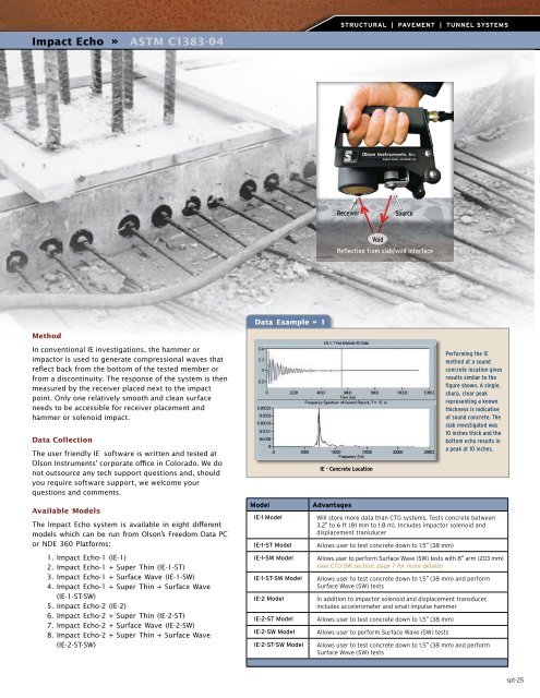
Method<br />
In conventional IE investigations, the hammer or<br />
impactor is used to generate compressional waves that<br />
reflect back from the bottom of the tested member or<br />
from a discontinuity. The response of the system is then<br />
measured by the receiver placed next to the impact<br />
point. Only one relatively smooth and clean surface<br />
needs to be accessible for receiver placement and<br />
hammer or solenoid impact.<br />
Data Collection<br />
The user friendly IE software is written and tested at<br />
<strong>Olson</strong> <strong>Instruments</strong>’ corporate office in Colorado. We do<br />
not outsource any tech support questions and, should<br />
you require software support, we welcome your<br />
questions and comments.<br />
Available Models<br />
The Impact Echo system is available in eight different<br />
models which can be run from <strong>Olson</strong>’s Freedom Data PC<br />
or NDE 360 Platforms:<br />
1. Impact Echo-1 (IE-1)<br />
2. Impact Echo-1 + Super Thin (IE-1-ST)<br />
3. Impact Echo-1 + Surface Wave (IE-1-SW)<br />
4. Impact Echo-1 + Super Thin + Surface Wave<br />
(IE-1-ST-SW)<br />
5. Impact Echo-2 (IE-2)<br />
6. Impact Echo-2 + Super Thin (IE-2-ST)<br />
7. Impact Echo-2 + Surface Wave (IE-2-SW)<br />
8. Impact Echo-2 + Super Thin + Surface Wave<br />
(IE-2-ST-SW)<br />
Model<br />
IE-1 Model<br />
IE-1-ST Model<br />
IE-1-SW Model<br />
IE-1-ST-SW Model<br />
IE-2 Model<br />
IE-2-ST Model<br />
IE-2-SW Model<br />
IE-2-ST-SW Model<br />
IE - Concrete Location<br />
Advantages<br />
Will store more data than CTG systems. Tests concrete between<br />
3.2" to 6 ft (81 mm to 1.8 m). <strong>Inc</strong>ludes impactor solenoid and<br />
displacement transducer<br />
Allows user to test concrete down to 1.5" (38 mm)<br />
Allows user to perform Surface Wave (SW) tests with 8" arm (203 mm)<br />
(see CTG-SW section, page 7 for more details)<br />
Allows user to test concrete down to 1.5" (38 mm) and perform<br />
Surface Wave (SW) tests<br />
In addition to impactor solenoid and displacement transducer,<br />
includes accelerometer and small impulse hammer<br />
Allows user to test concrete down to 1.5" (38 mm)<br />
Allows user to perform Surface Wave (SW) tests<br />
Performing the IE<br />
method at a sound<br />
concrete location gives<br />
results similar to the<br />
figure shown. A single,<br />
sharp, clear peak<br />
representing a known<br />
thickness is indicative<br />
of sound concrete. The<br />
slab investigated was<br />
10 inches thick and the<br />
bottom echo results in<br />
a peak at 10 inches.<br />
Allows user to test concrete down to 1.5" (38 mm) and perform<br />
Surface Wave (SW) tests<br />
spt-25