OI Catalog - Olson Instruments, Inc.
OI Catalog - Olson Instruments, Inc.
OI Catalog - Olson Instruments, Inc.

You also want an ePaper? Increase the reach of your titles
YUMPU automatically turns print PDFs into web optimized ePapers that Google loves.
structural | PAVEMENT | tunnel systems<br />
Ultrasonic Pulse Velocity/Sonic Pulse Velocity » ASTM C597-02, E494-95 | BSI 98/105795 | ACI 228.2R<br />
Method<br />
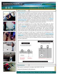
Conventional UPV testing requires access to two surfaces,<br />
preferably two parallel surfaces such as the top and bottom<br />
surfaces of a slab or the inside and outside surfaces of a wall.<br />
This test can be performed, however, using the indirect<br />
method (figure on previous page) which does not require<br />
access to two surfaces. In defect areas, the compressional<br />
wave velocity is slower than in sound areas and signal<br />
amplitude is often lower. For structural members containing<br />
large, severe voids, signal transmission may be completely<br />
lost. In some defect areas, such as honeycombs, the<br />
compressional wave velocity may be almost the same as in<br />
sound areas, but distortion of the signal (filtering of high<br />
frequencies) may be used as an indication of a honeycomb defect.<br />
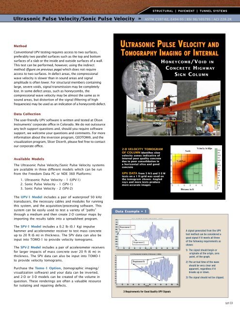
UL T R A S O PU N L I S EVE C L O C I T A Y N D<br />
TOM O G R A P H YIM A G I O N F G IN T E R N A L<br />
H O N E Y C O M B /VO I D I N<br />
C O N C R E T E HI G H W A Y<br />
S I G N CO L U M N<br />
Data Collection<br />
The user-friendly UPV software is written and tested at <strong>Olson</strong><br />
<strong>Instruments</strong>’ corporate office in Colorado. We do not outsource<br />
any tech support questions and, should you require software<br />
support, we welcome your questions and comments. For more<br />
information about the inversion program, GEOTOM®, and the<br />
visualization program, Slicer Dicer®, please feel free to contact<br />
our corporate office.<br />
Available Models<br />
The Ultrasonic Pulse Velocity/Sonic Pulse Velocity systems<br />
are available in three different models which can be run<br />
from the Freedom Data PC or NDE 360 Platforms:<br />
1. Ultrasonic Pulse Velocity - 1 (UPV-1)<br />
2. Sonic Pulse Velocity - 1 (SPV-1)<br />
3. Sonic Pulse Velocity - 2 (SPV-2)<br />
The UPV-1 Model includes a pair of waterproof 50 kHz<br />
transducers, the necessary cables and modules for running<br />
this system, and the acquisition/processing software. This<br />
system can be easily used to test a variety of “paths”<br />
through a medium and then create 2-D contour maps by<br />
importing the results table into a spreadsheet program.<br />
2-D VELOCITY TOMOGRAM<br />
OF COLUMN identifies slow<br />
velocity zones indicative of<br />
internal poor quality concrete<br />
due to poor consolidation in<br />
a horizontal slice and good<br />
concrete<br />
UPV DATA from 5 N-S and 5 E-W<br />
tests on a 1 ft grid was used on<br />
the tomogram shown. Angled<br />
rays and more tests produce<br />
more accurate images<br />
Data Example » 1<br />
The SPV-1 Model includes a 0.2 lb (0.1 Kg) impulse<br />
hammer and accelerometer receiver to test mass concrete<br />
up to 20 ft (6 m) in thickness. The SPV data can also be<br />
input into TOMO-1 to provide velocity tomograms.<br />
The SPV-2 Model includes a pair of accelerometer receivers<br />
for larger impacts of mass concrete over 20 ft (6 m) in<br />
thickness. The SPV data can also be input into TOMO-1<br />
to provide velocity tomograms.<br />
Purchase the Tomo -1 Option, (tomographic imaging/<br />
visualization software) and your data can be inverted,<br />
and 2-D or 3-D models can be created of the volume in<br />
question. These renderings are often a valuable resource<br />
for isolating and repairing defects.<br />
A signal generated from the UPV<br />
test method can be considered a<br />
good signal if it meets all three<br />
of the following requirements as<br />
shown:<br />
1) The signal should begin or<br />
originate at the origin, zero<br />
point, of the graph.<br />
2) The arrival time of the wave<br />
should be very clear and<br />
apparent, regardless if it<br />
breaks up or down.<br />
3) The signal should not be clipped.<br />
3 Requirements for Good Quality UPV Signals<br />
spt-33