OI Catalog - Olson Instruments, Inc.
OI Catalog - Olson Instruments, Inc.
OI Catalog - Olson Instruments, Inc.

You also want an ePaper? Increase the reach of your titles
YUMPU automatically turns print PDFs into web optimized ePapers that Google loves.
structural | PAVEMENT | tunnel systems<br />
Ultrasonic Pulse Velocity/Sonic Pulse Velocity » ASTM C597-02, E494-95 | BSI 98/105795 | ACI 228.2R<br />
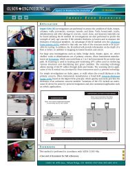
Ultrasonic Pulse Velocity (UPV) investigations are performed to assess the condition of structural members such as<br />
elevated slabs, beams, and columns when access to both sides is available. Sonic Pulse Velocity (SPV) is performed<br />
on mass concrete over 10 ft (3 m) in thickness.<br />
The Ultrasonic Pulse Velocity (UPV) systems are designed to<br />
identify and map voids, honeycomb, cracks, delaminations, and<br />
other damage in concrete, wood, masonry, stone, ceramics, and<br />
metal materials. UPV tests are also performed to predict strength<br />
of early age concrete. The UPV methodology relies on direct<br />
arrival of compressional waves, which are generated by sources<br />
with resonant frequencies ranging from 50 to 150 kHz. The<br />
highest resonant frequency sources/receivers are typically used<br />
with thinner structural members for higher resolution and smaller<br />
anomaly identification.<br />
Features:<br />
■■ ~ 50 kHz UPV transducers standard<br />
■■ Short learning curve for data acquisition and basic processing<br />
■■ Real-time waveform display while testing<br />
■■ System is compact, durable, and easily transported allowing<br />
for multiple tests per day<br />
■■ 2-D maps are easily generated from data by exporting the<br />
tables from WinUPV into Excel<br />
■■ Tomographic velocity images can be generated from this data<br />
giving the user a 2-D or 3-D visual tool of the region in question<br />
■■ English or Metric units can be used<br />
■■ System includes a calibration bar as per ASTM and other standards<br />
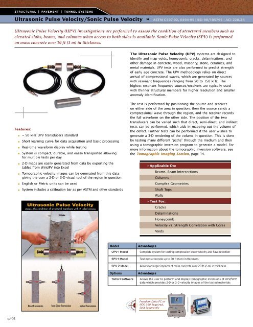
Ultrasonic Pulse Velocity<br />
Assess the condition of structural members with 2 sided access<br />
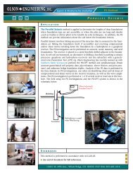
The test is performed by positioning the source and receiver<br />
on either side of the area in question, then the source sends a<br />
compressional wave through the region, and the receiver records<br />
the full waveform on the other side. The position of the two<br />
transducers can be varied such that direct, semi-direct, and indirect<br />
tests can be performed, which aids in mapping out the volume of<br />
the defect. Further tests can be performed if the user wishes to<br />
generate a 3-D rendering of the volume in question. This is done<br />
by testing many different “paths” through the medium and then<br />
using a tomographic inversion program to generate a model. For<br />
more information about the tomographic inversion software, see<br />
the Tomographic Imaging Section, page 14.<br />
» Applicable On:<br />
Beams, Beam Intersections<br />
Columns<br />
Complex Geometries<br />
Shaft Tops<br />
Walls<br />
» Test For:<br />
Cracks<br />
Delaminations<br />
Honeycomb<br />
Velocity vs. Strength Correlation with Cores<br />
Voids<br />
Model<br />
UPV-1 Model<br />
SPV-1 Model<br />
SPV-2 Model<br />
Advantages<br />
Complete system for testing compression wave velocity and flaw detection<br />
Test mass concrete up to 20 ft (6 m) in thickness<br />
Allows for larger impacts of mass concrete over 20 ft (6 m) in thickness<br />
Options<br />
Tomo-1 Software<br />
Advantages<br />
Allows the user to perform and display tomographic inversions of UPV/SPV<br />
data which provides 2-D or 3-D velocity images of the tested materials<br />
Direct Transmission Semi-Direct Transmission Indirect Transmission<br />
Freedom Data PC or<br />
NDE 360 Required,<br />
Sold Separately<br />
spt-32