ExaRAID JBOD Quick Installation Guide - Accusys
ExaRAID JBOD Quick Installation Guide - Accusys
ExaRAID JBOD Quick Installation Guide - Accusys

Create successful ePaper yourself
Turn your PDF publications into a flip-book with our unique Google optimized e-Paper software.
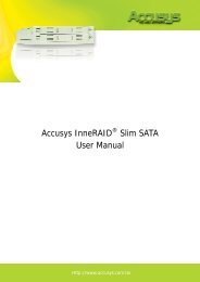
A16R-SJ <strong>Quick</strong> Start <strong>Guide</strong><br />
A12/16/24R/U-SJ<br />
<strong>Quick</strong> Start <strong>Guide</strong><br />
<strong>ExaRAID</strong> <strong>JBOD</strong> SYSTEM<br />
USER'S GUIDE<br />
1
A16R-SJ <strong>Quick</strong> Start <strong>Guide</strong><br />
A12/16/24R/U-SJ<br />
<strong>Quick</strong> Start <strong>Guide</strong><br />
42-33000-5030<br />
<strong>ExaRAID</strong> <strong>JBOD</strong> SYSTEM<br />
Version:1.1<br />
1
<strong>JBOD</strong> System <strong>Quick</strong> Start <strong>Guide</strong><br />
A16R-SJ <strong>JBOD</strong> Task List<br />
Step 1: Unpacking the <strong>JBOD</strong> System below<br />
Step 2: Mounting the <strong>JBOD</strong> System in a Rack on page 10<br />
Step 3: Installing Disk Drives on page 12<br />
Step 4: Making Connections on page 16<br />
Step 5: Powering on the System on page 19<br />
Step 6: Configuring the <strong>JBOD</strong> system on page 20<br />
Step 7: Host Configuration on page 26<br />
Step 8: Powering Off the System on page 27<br />
Step 1: Unpacking the <strong>JBOD</strong> System<br />
The following items come with the <strong>JBOD</strong> system package, if any of them<br />
is missing or damaged, please contact your supplier:<br />
1<br />
1. Hard disk tray: A12R/U-SJ x 12<br />
A16R/U-SJ x 16<br />
A24R/U-SJ x 24<br />
2. SAS cable: A12/A16/A24U-SJ x 1<br />
A12/A16/A24R-SJ x 2<br />
6<br />
7<br />
8<br />
9<br />
10<br />
11<br />
<strong>Quick</strong> Start <strong>Guide</strong><br />
2<br />
3<br />
4<br />
5<br />
3. Front panel key x 2<br />
4. Power cable: A12/A16R/U-SJ x 2<br />
A24R/U-SJ x 3<br />
5. <strong>Quick</strong> Start <strong>Guide</strong><br />
6. M5 fix screw x 2 packs<br />
7. M6 fix screw x 2 packs<br />
12<br />
8. UNC #10-32 fix screw x 2 packs<br />
9. HDD screw x 3 packs<br />
10. Rail x 1 set<br />
11. Rail extender x 1 set<br />
12. <strong>JBOD</strong> system<br />
1
<strong>JBOD</strong> System <strong>Quick</strong> Start <strong>Guide</strong><br />
Front Panel View (Closed)<br />
A12R/U-SJ<br />
1 2 3 4 5 6 7 8<br />
Power<br />
IO#2 ACT<br />
IO#1 ACT<br />
IO#2 RDY<br />
IO#1 RDY<br />
HDD<br />
Temp<br />
Fan<br />
9<br />
IO#2 ACT<br />
IO#1 ACT<br />
IO#2 RDY<br />
IO#1 RDY<br />
HDD<br />
Temp<br />
Fan<br />
Power<br />
A16R/U-SJ<br />
1 2 3 4 5 6 7 8<br />
Power<br />
IO#2 ACT<br />
IO#1 ACT<br />
IO#2 RDY<br />
IO#1 RDY<br />
HDD<br />
Temp<br />
Fan<br />
9<br />
IO#2 ACT<br />
IO#1 ACT<br />
IO#2 RDY<br />
IO#1 RDY<br />
HDD<br />
Temp<br />
Fan<br />
Power<br />
A24R/U-SJ<br />
1 2 3 4 5 6 7 8<br />
Power<br />
IO#2 ACT<br />
IO#1 ACT<br />
IO#2 RDY<br />
IO#1 RDY<br />
HDD<br />
Temp<br />
Fan<br />
9<br />
IO#2 ACT<br />
IO#1 ACT<br />
IO#2 RDY<br />
IO#1 RDY<br />
HDD<br />
Temp<br />
Fan<br />
Power<br />
No. Item Description<br />
1 Power LED<br />
• Green - Power supplies are installed and<br />
working properly.<br />
• Red - The <strong>JBOD</strong> system has a faulty power<br />
supply.<br />
2
<strong>JBOD</strong> System <strong>Quick</strong> Start <strong>Guide</strong><br />
No. Item Description<br />
2 Fan LED<br />
3 Temp LED<br />
4 HDD LED<br />
• Green - Fan modules are installed and<br />
working properly.<br />
• Red - The <strong>JBOD</strong> system has a faulty fan<br />
module.<br />
• Green - The <strong>JBOD</strong> system temperature is<br />
below 55ºC.<br />
• Red - The <strong>JBOD</strong> system temperature<br />
exceeds 55ºC.<br />
• Green - All installed disks are working<br />
properly.<br />
• Red - The <strong>JBOD</strong> system has a faulty hard<br />
disk.<br />
5 IO#1 RDY Indicates <strong>JBOD</strong> controller A is working properly.<br />
6 IO#2 RDY Indicates <strong>JBOD</strong> controller B is working properly.<br />
7 IO#1 ACT<br />
Indicates data activity in progress between host<br />
and <strong>JBOD</strong> controller A.<br />
8 IO#2 ACT<br />
Indicates data activity in progress between host<br />
and <strong>JBOD</strong> controller B.<br />
9 Lock Locks the front cover<br />
3
<strong>JBOD</strong> System <strong>Quick</strong> Start <strong>Guide</strong><br />
Front Panel View (Open)<br />
A12R/U-SJ<br />
1 2 3 4 5 6 7 8 9 10 11 12<br />
13<br />
No. Item Description<br />
1-12 Disk trays 12 Removal disk trays.<br />
13 Front panel door Protects the disks.<br />
A16R/U-SJ<br />
1<br />
2 3 4 5 6 7 8 9 10 11 12 13 14 15 16<br />
17<br />
No. Item Description<br />
1-16 Disk trays 16 Removal disk trays.<br />
17 Front panel door Protects the disks.<br />
A24R/U-SJ<br />
1<br />
3 5<br />
2 4 6<br />
7 9 11 13 15 17 19 21 23<br />
8 10 12 14 16 18 20 22 24<br />
25<br />
No. Item Description<br />
1-24 Disk trays 24 Removal disk trays.<br />
25 Front panel door Protects the disks.<br />
4
<strong>JBOD</strong> System <strong>Quick</strong> Start <strong>Guide</strong><br />
Disk Tray<br />
Front View<br />
3 2<br />
1<br />
4<br />
No. Item Description<br />
• Green - Disk is online<br />
1 Disk LED<br />
• Red - No disk or disk fail<br />
2 Tray button Press to release the tray handle.<br />
3 Access LED indicator<br />
Lights blue when the disk is being<br />
accessed.<br />
4 Tray handle<br />
Use to pull out or lock the disk tray into<br />
place.<br />
5
2<br />
2<br />
3<br />
3<br />
4<br />
4<br />
<strong>JBOD</strong> System <strong>Quick</strong> Start <strong>Guide</strong><br />
Rear View<br />
A12R-SJ<br />
A12U-SJ<br />
1<br />
2 3 4 5 6 7<br />
8 9 10<br />
1<br />
2 3 4 5 6 7 8 9 10<br />
1<br />
U<br />
PS<br />
1 5<br />
ON DIP<br />
2<br />
1<br />
U<br />
PS<br />
1 5<br />
ON DIP<br />
2<br />
A<br />
EXP CH 1 CH 2 EXP CH 1 CH 2<br />
B<br />
A<br />
EXP CH 1 CH 2<br />
B<br />
11<br />
12 13 14 15 16 17 18<br />
11<br />
12 13 14<br />
No. Item Description<br />
1 AC power port Connects to the power source.<br />
2 Power supply handle Use to pull out the power supply.<br />
3 Power supply switch Use to switch the power on or off.<br />
4 Cooling fan 1 System cooling fan.<br />
5 Chassis ID<br />
6 UPS port<br />
Use for <strong>JBOD</strong> enclosure only, See Switch<br />
ID on page 9.<br />
Data port for uninterruptable power<br />
supply.<br />
7 AC power port Connects to the power source.<br />
8 Power supply handle Use to pull out the power supply.<br />
9 Power supply switch Use to switch the power on or off.<br />
10 Cooling fan 2 System cooling fan.<br />
11 <strong>JBOD</strong> Controller A <strong>JBOD</strong> controller.<br />
12 Expansion port (Controller A) Use for <strong>JBOD</strong> expansion.<br />
13 Host channel 1 (Controller A)<br />
14 Host channel 2 (Controller A)<br />
15 <strong>JBOD</strong> Controller B <strong>JBOD</strong> controller.<br />
Connects to EXP port on RAID system or<br />
SAS HBA card of host.<br />
Connects to EXP port on RAID system or<br />
SAS HBA card of host.<br />
16 Expansion port (Controller B) Use for <strong>JBOD</strong> expansion.<br />
17 Host channel 1 (Controller B)<br />
18 Host channel 2 (Controller B)<br />
Connects to EXP port on RAID system or<br />
SAS HBA card of host.<br />
Connects to EXP port on RAID system or<br />
SAS HBA card of host.<br />
6
0567 89<br />
0567 89<br />
<strong>JBOD</strong> System <strong>Quick</strong> Start <strong>Guide</strong><br />
A16R-SJ<br />
1 2 3 4 5 6 7 8 9 10 11<br />
A16U-SJ<br />
1 2 3 4 5 6<br />
Fan 1 Fan 3<br />
Fan 2<br />
Fan 1 Fan 3<br />
Fan 2<br />
Contraller A<br />
Contraller B<br />
Contraller A<br />
Contraller B<br />
EXP CH 1 CH 2 EXP CH 1 CH 2<br />
EXP CH 1 CH 2<br />
P/S 1 P/S 2<br />
P/S Chassis<br />
ID<br />
UPS<br />
P/S 1 P/S 2<br />
P/S Chassis<br />
ID<br />
UPS<br />
12 34<br />
12 34<br />
VER 1.0<br />
VER 1.0<br />
12 13 14 15 16 17 18 19 20 21<br />
12 13 14 15 16 17 18 19 20 21<br />
No. Item Description<br />
1 Cooling fan 1 System cooling fan.<br />
2 <strong>JBOD</strong> Controller A <strong>JBOD</strong> controller.<br />
3 Expansion port (Controller A) Use for <strong>JBOD</strong> expansion.<br />
4 Host channel 1 (Controller A)<br />
Connects to EXP port on RAID system or<br />
SAS HBA card of host.<br />
5 Host channel 2 (Controller A)<br />
6 Cooling fan 3 System cooling fan.<br />
7 <strong>JBOD</strong> Controller B <strong>JBOD</strong> controller.<br />
Connects to EXP port on RAID system or<br />
SAS HBA card of host.<br />
8 Expansion port (Controller B) Use for <strong>JBOD</strong> expansion.<br />
9 Host channel 1 (Controller B)<br />
10 Host channel 2 (Controller B)<br />
11 Cooling fan 2 System cooling fan.<br />
Connects to EXP port on RAID system or<br />
SAS HBA card of host.<br />
Connects to EXP port on RAID system or<br />
SAS HBA card of host.<br />
12 AC power port Connects to the power source.<br />
13 Power supply 1 Removable power supply.<br />
14 Power supply handle Use to pull out the power supply.<br />
15 Power supply switch Use to switch the power on or off.<br />
16 Chasis ID switch Use for <strong>JBOD</strong> enclosure only.<br />
17 UPS port<br />
Data port for uninterruptable power<br />
supply.<br />
18 IO tray Holds the IO board and BBMs.<br />
19 AC power port Connects to the power source.<br />
20 Power supply 2 Removable power supply.<br />
21 Power supply handle Use to pull out the power supply.<br />
7
0567 89<br />
12 34<br />
0567 89<br />
12 34<br />
<strong>JBOD</strong> System <strong>Quick</strong> Start <strong>Guide</strong><br />
A24R-SJ<br />
1 2 3 4 5 6 7 8 9 10 11 12<br />
A24U-SJ<br />
1 2 3 4 5 6 7 12<br />
Fan 1<br />
Fan 3 Fan 4 Fan 2<br />
Fan 1<br />
Fan 3 Fan 4 Fan 2<br />
EXP CH 1 CH 2 EXP CH 1 CH 2<br />
EXP CH 1 CH 2<br />
Contraller A<br />
Chassis ID<br />
Contraller B<br />
Contraller A<br />
Chassis ID<br />
Contraller B<br />
P/S 1 P/S 3 P/S 2<br />
UPS<br />
P/S 1 P/S 3 P/S 2<br />
UPS<br />
13 14 15 16 17 18 19 20 21 22 23<br />
13 14 15 16 17 18 19 20 21 22 23<br />
No. Item Description<br />
1 Cooling fan 1 System cooling fan.<br />
2 <strong>JBOD</strong> Controller A <strong>JBOD</strong> controller.<br />
3 Expansion port (Controller A) Use for <strong>JBOD</strong> expansion.<br />
4 Host channel 1 (Controller A)<br />
5 Host channel 2 (Controller A)<br />
6 Cooling fan 3 System cooling fan.<br />
7 Cooling fan 4 System cooling fan.<br />
8 <strong>JBOD</strong> Controller B <strong>JBOD</strong> controller.<br />
Connects to EXP port on RAID system or<br />
SAS HBA card of host.<br />
Connects to EXP port on RAID system or<br />
SAS HBA card of host.<br />
9 Expansion port (Controller B) Use for <strong>JBOD</strong> expansion.<br />
10 Host channel 1 (Controller B)<br />
11 Host channel 2 (Controller B)<br />
12 Cooling fan 2 System cooling fan.<br />
Connects to EXP port on RAID system or<br />
SAS HBA card of host.<br />
Connects to EXP port on RAID system or<br />
SAS HBA card of host.<br />
13 AC power port Connects to the power source.<br />
14 Power supply 1 Removable power supply.<br />
15 Power supply handle Use to pull out the power supply.<br />
16 Power supply switch Use to switch the power on or off.<br />
17 AC power port Connects to the power source.<br />
18 Power supply 3 Removable power supply.<br />
19 Power supply handle Use to pull out the power supply.<br />
20 UPS port<br />
Data port for uninterruptable power<br />
supply.<br />
21 AC power port Connects to the power source.<br />
8
<strong>JBOD</strong> System <strong>Quick</strong> Start <strong>Guide</strong><br />
No. Item Description<br />
22 Power supply 2 Removable power supply.<br />
23 Power supply handle Use to pull out the power supply.<br />
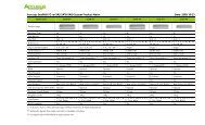
Switch ID<br />
See table below on how to set the Chassis ID.<br />
2U-12R/U Chassis ID<br />
ID1(A3) ID2(A2) ID3(A1) ID4(A0) ID5 Chassis ID FC-HDD Speed Remark<br />
0 2G<br />
1 4G<br />
0 0 0 0 0<br />
0 0 0 1 1<br />
0 0 1 0 2<br />
0 0 1 1 3<br />
0 1 0 0 4<br />
0 1 0 1 5<br />
0 1 1 0 6<br />
0 1 1 1 7<br />
1 0 0 0 8 N/A<br />
1 0 0 1 9 N/A<br />
ON(1)<br />
OFF(0)<br />
1<br />
2<br />
3<br />
4<br />
5<br />
ID1<br />
ID2<br />
ID3<br />
ID4<br />
ID5<br />
9
IO#2 ACT<br />
IO#1 ACT<br />
IO#2 RDY<br />
IO#1 RDY<br />
HDD<br />
Temp<br />
Fan<br />
Power<br />
<strong>JBOD</strong> System <strong>Quick</strong> Start <strong>Guide</strong><br />
Step 2: Mounting the <strong>JBOD</strong> System in a Rack<br />
The <strong>JBOD</strong> system can be installed in a standard 19-inch rack. Follow the<br />
procedures below:<br />
1.Attack eight rack nuts into the rack,<br />
making sure that they correspond with<br />
the mounting points on the rails.<br />
2.Adjust the length of the rails as<br />
needed.<br />
3.Secure the rails using two nuts and<br />
bolts on both the front and back posts<br />
of the rack.<br />
4.Tighten the locking screws.<br />
5.Slide the <strong>JBOD</strong> system into the rack<br />
and secure it into place using the<br />
fixing screws.<br />
10
IO#2 ACT<br />
IO#1 ACT<br />
IO#2 RDY<br />
IO#1 RDY<br />
HDD<br />
Temp<br />
Fan<br />
Power<br />
<strong>JBOD</strong> System <strong>Quick</strong> Start <strong>Guide</strong><br />
Using the Rail Extenders<br />
Follow the procedures below to install the rail extenders:<br />
1.Install the rail extenders and attach the screws to secure them.<br />
2.Slide the RAID system into the rack and secure it into place using the<br />
fixing screws.<br />
11
220<br />
20<br />
220<br />
<strong>JBOD</strong> System <strong>Quick</strong> Start <strong>Guide</strong><br />
Step 3: Installing Disk Drives<br />
The <strong>JBOD</strong> system supportS SAS or SATA interface hard drives.<br />
SAS hard disks<br />
Follow the procedures below to install SAS hard drives:<br />
1.Insert the SAS hard drive into the hard disk tray. Screw the sides to<br />
secure the hard disk. Repeat this procedure to install more hard disks.<br />
2.Insert the key to the key slot and turn to unlock the front panel door.<br />
A16R-SJ<br />
A12R-SJ / A24R-SJ<br />
3.Pull open the front panel door.<br />
12
<strong>JBOD</strong> System <strong>Quick</strong> Start <strong>Guide</strong><br />
4.Insert the hard disk tray into the empty slot.<br />
5.Push down the tray handle to secure the hard disk tray into place.<br />
6.Repeat steps 4 to 5 until all the required disks have been installed.<br />
7.Close the front panel door, then lock it.<br />
13
<strong>JBOD</strong> System <strong>Quick</strong> Start <strong>Guide</strong><br />
SATA hard disks<br />
SATA hard drive installation requires an AA-MUX adapter to be installed<br />
on the hard disk tray first before installing the SATA hard disk.<br />
Note<br />
AA-MUX is an optional accessory and is sold separately. Contact your<br />
supplier to purchase one.<br />
Follow the procedures below to install SATA hard disks:<br />
1.Place the AA-MUX adapter on the hard disk tray and attach the four<br />
screws as shown.<br />
2.Place the hard disk into the hard disk tray with the drive connectors<br />
facing the AA-MUX adapter.<br />
14
<strong>JBOD</strong> System <strong>Quick</strong> Start <strong>Guide</strong><br />
3.Slide the hard disk towards the AA-MUX adapter and connect the<br />
power and data connectors.<br />
4.Attach the screws to secure the hard disk.<br />
5.Insert the hard disk tray into an empty slot.<br />
6.Push down the tray handle to secure the hard disk tray into place.<br />
7.Repeat steps 1 to 6 until all the required disks have been installed.<br />
8.Close the front panel door, then lock it.<br />
15
<strong>JBOD</strong> System <strong>Quick</strong> Start <strong>Guide</strong><br />
Step 4: Making Connections<br />
The <strong>JBOD</strong> system has two controllers, each controller has three x4 SAS<br />
ports that enables you to connect to a host computer, a RAID system or<br />
expand the <strong>JBOD</strong> enclosure.<br />
Use a x4 SAS cable to connect the <strong>JBOD</strong> system to a host computer or to<br />
a RAID system. Follow the procedures below:<br />
1.Insert the SAS cable into the CH1 port of A16R-SJ.<br />
A<br />
2.To connect to a RAID system, insert the other end of the SAS cable to<br />
the EXP port of the RAID system(B). Or to connect to a host server,<br />
insert the other end of the SAS cable to the HBA connector of the host<br />
server (C).<br />
B<br />
C<br />
RAID system connection. A16R-FS<br />
Fibre RAID system is shown above.<br />
HBA card of host server<br />
Note<br />
To configure, see Step 6: Configuring the <strong>JBOD</strong> system.<br />
16
Expanding <strong>JBOD</strong> Enclosures<br />
<strong>JBOD</strong> System <strong>Quick</strong> Start <strong>Guide</strong><br />
You can expand a maximum of seven <strong>JBOD</strong> enclosures to a RAID system.<br />
Figure 1-1 shows a RAID system with three <strong>JBOD</strong> enclosures in a loop. The<br />
loop connection works to ensure the system can continue with its<br />
operation without interruption even if any of the <strong>JBOD</strong> fails. Once a <strong>JBOD</strong><br />
fails, the other two can still continue to transmit data around the loop via<br />
the redundant path.<br />
A16R-FS/ A16R-SS (RAID)<br />
Chassis ID = 0<br />
A16R-SJ (<strong>JBOD</strong>1)<br />
Chassis ID = 1<br />
A16R-SJ (<strong>JBOD</strong>2)<br />
Chassis ID = 2<br />
A16R-SJ (<strong>JBOD</strong>3)<br />
Chassis ID = 3<br />
Figure 1-1 RAID system with <strong>JBOD</strong> enclosure in a loop<br />
17
<strong>JBOD</strong> System <strong>Quick</strong> Start <strong>Guide</strong><br />
To establish the connection:<br />
1.Connect the RAID system EXP port to the CH1 port of the <strong>JBOD</strong>1 using a<br />
SAS cable.<br />
2.To connect to the next <strong>JBOD</strong>, connect the EXP port of <strong>JBOD</strong>1 to the<br />
CH1 port of <strong>JBOD</strong>2.<br />
3.Follow the same procedures to connect the succeeding <strong>JBOD</strong><br />
enclosures.<br />
4.To make a loop, connect the EXP port of <strong>JBOD</strong>3 to the CH1 port of<br />
<strong>JBOD</strong>2.<br />
5.Connect the EXP port of <strong>JBOD</strong>2 to the CH1 port of <strong>JBOD</strong>1.<br />
6.Connect the EXP port of the RAID system to the CH1 port of <strong>JBOD</strong>3.<br />
7.Set the chassis ID:<br />
• A16R-FS (RAID) = 0<br />
• A16R-SJ (<strong>JBOD</strong>1) = 1<br />
• A16R-SJ (<strong>JBOD</strong>2) = 2<br />
• A16R-SJ (<strong>JBOD</strong>3) = 3; and so forth for more <strong>JBOD</strong> enclosures<br />
Note<br />
For more information, see 2.3 SAS <strong>JBOD</strong> Enclosure Display on the<br />
<strong>Accusys</strong> RAID GUI user’s manual.<br />
To configure, see Step 6: Configuring the <strong>JBOD</strong> system.<br />
18
<strong>JBOD</strong> System <strong>Quick</strong> Start <strong>Guide</strong><br />
Step 5: Powering on the System<br />
Connecting the Power<br />
1.Plug one power cable into the AC power port.<br />
1<br />
A12R/U-SJ<br />
A16R/U-SJ<br />
A24R/U-SJ<br />
P/S 1<br />
Contraller A<br />
2.Plug the second power cable into the other AC power port.<br />
Once all the components have been connected, the system can now<br />
be powered on using the power switch.<br />
Power on the system in the following order:<br />
• <strong>JBOD</strong> system(s)<br />
• RAID system<br />
• Host server<br />
19
<strong>JBOD</strong> System <strong>Quick</strong> Start <strong>Guide</strong><br />
Note<br />
Before turning the system on, make sure the chassis ID switch has<br />
been set properly.<br />
When the <strong>JBOD</strong> system is successfully installed and powered on,<br />
Power, Fan, TEMP, and HDD will turn green and IO1 and IO2 RDY<br />
LEDs will flash green.<br />
Step 6: Configuring the <strong>JBOD</strong> system<br />
Configuring Host Server Connection<br />
Figure 1-2 shows an example of two A16R-SJ connected to the host<br />
server.<br />
Host Sever<br />
TV OUT<br />
SAS Card<br />
Controller A<br />
Controller B<br />
Controller A<br />
Controller B<br />
Figure 1-2 Host server connection with <strong>JBOD</strong> expansion<br />
Note<br />
The same procedures apply to A12R-SJ and A24R-SJ RAID systems<br />
when using SAS connectors.<br />
20
<strong>JBOD</strong> System <strong>Quick</strong> Start <strong>Guide</strong><br />
To configure the connection using Windows, follow the procedures<br />
below:<br />
Note<br />
The following procedures are based on Windows server 2003 R2.<br />
Make sure you are installing in Windows 32-bit or 64-bit.<br />
1.Open the folder with the installation files for Windows 32-bit or 64-bit.<br />
2.To check the configuration, open Computer Management > Device<br />
Manager.<br />
• Check if all the hard disk installed in the <strong>JBOD</strong> are detected.<br />
21
<strong>JBOD</strong> System <strong>Quick</strong> Start <strong>Guide</strong><br />
Configuring the RAID System<br />
Figure 1-3 shows an example of a RAID system (A16R-FS) connected to<br />
three <strong>JBOD</strong>s.<br />
Note<br />
The same procedures apply to A16R-SS RAID system using SAS<br />
connectors.<br />
The same procedures apply when using SAS: A12R-SS / A24R-SS<br />
connectors to A12R-FS / A24R-FS RAID systems.<br />
Host Sever<br />
LAN Switch<br />
TV OUT<br />
Fibre Card 1<br />
Fibre Card 2<br />
A16R-FS/SS<br />
ID : 0<br />
A16R-SJ<br />
ID : 1<br />
A16R-SJ<br />
ID : 2<br />
A16R-SJ<br />
ID : 3<br />
Figure 1-3 RAID system with <strong>JBOD</strong> expansion<br />
To establish the connection, follow the procedures below:<br />
1.Connect the RAID system and the <strong>JBOD</strong> enclusures following the<br />
procedures inExpanding <strong>JBOD</strong> Enclosures on page 17.<br />
2.Connect the RAID system to the host server using fibre cables as shown.<br />
22
<strong>JBOD</strong> System <strong>Quick</strong> Start <strong>Guide</strong><br />
3.Connect controller A and controller B of the RAID system to the LAN<br />
switch.<br />
4.Connect the host server to the LAN switch.<br />
This connection can be configured using GUI (Graphical User Interface)<br />
or CLI (Command Line Interface).<br />
• To configure using GUI<br />
The <strong>JBOD</strong> system can be detected automatically by the GUI when<br />
connected. The chassis ID corresponds to the enclosure tab number<br />
shown in the GUI. The number of enclosure tabs may vary according to<br />
the number of connected <strong>JBOD</strong> systems. The connection in Figure 1-3 will<br />
show three <strong>JBOD</strong> enclosure tabs. The enclosure display may show empty<br />
slots depending on the number of drives installed. The following table<br />
shows the supported number of <strong>JBOD</strong> systems and hard disks.<br />
A12R-SJ<br />
<strong>JBOD</strong> System<br />
12-bay<br />
Memory size<br />
Units of HDD<br />
Number of <strong>JBOD</strong><br />
Enclosure<br />
1G 64 5*<br />
2G or higher 120 9<br />
* When there are 5 <strong>JBOD</strong> enclosures, the last <strong>JBOD</strong> can only contain 8 disks.<br />
A16R-SJ<br />
<strong>JBOD</strong> System<br />
16-bay<br />
A24R-SJ<br />
<strong>JBOD</strong> System<br />
24-bay<br />
Memory size<br />
Units of HDD<br />
Number of <strong>JBOD</strong><br />
Enclosure<br />
1G 64 3<br />
2G or higher 120 7<br />
Memory size<br />
Units of HDD<br />
Number of <strong>JBOD</strong><br />
Enclosure<br />
1G 64 3*<br />
2G or higher 120 4<br />
* When there are 3 <strong>JBOD</strong> enclosures, the last <strong>JBOD</strong> can only contain 16 disks.<br />
1.Connect and login to the GUI webpage.<br />
• Login name = admin<br />
• Password = 0000<br />
2.Check if the status of all the hard disks are unused.<br />
3.Create disk groups.<br />
4.Create logical disks.<br />
5.Create LUN mapping.<br />
23
<strong>JBOD</strong> System <strong>Quick</strong> Start <strong>Guide</strong><br />
Note<br />
For more details on GUI configuration, please see Chapter 2 Using<br />
the RAID GUI in the <strong>Accusys</strong> RAID GUI user’s manual.<br />
• To configure using CLI<br />
The Command Line Interface (CLI) is a set of commands which allows<br />
users to configure or monitor the system by entering lines of text through<br />
a variety of terminal consoles. For more information about the CLI<br />
commands, please refer to the software manual.<br />
To perform basic configurations, follow the steps below:<br />
1.Login to the CLI utility.<br />
2.Check the hard disk condition, type hddlist all in the command line<br />
(CLI>).<br />
3.Create disk groups using the dgcreate command.<br />
Command<br />
Synopsis<br />
Description<br />
dgcreate<br />
dgcreate dgi hddx hddy ... [-n name] [-i par/seq] [-z]<br />
[-s hddz,hdda, ...] [-t capacity]<br />
Create a disk group with member disks.<br />
24
<strong>JBOD</strong> System <strong>Quick</strong> Start <strong>Guide</strong><br />
Parameters<br />
[-n name]: the name of a disk group<br />
[-i par/seq]: logical disk initialization mode (parallel or<br />
sequential)<br />
[-z]: write-zero immediately<br />
[-s hddz,hdda, ...]: local spare disks<br />
[-t capacity]: capacity to truncate<br />
For example, to create disk group 0 (DG0), with hard disks 1 to 8 in the<br />
group, type the following in the command line:<br />
CLI>dgcreate dg0 hdd1 hdd2 hdd3 hdd4 hdd5 hdd6 hdd7 hdd8<br />
4.Create logical disks using the ldcreate command.<br />
Command<br />
Synopsis<br />
Description<br />
Parameters<br />
ldcreate<br />
ldcreate dgxldy capacity raidlevel [-s stripesize]<br />
[-i initopt] [-f x] [-o offset] [-n name] [-c ctlx]<br />
Create a logical disk.<br />
capacity: logical disk capacity<br />
raidlevel: raid0, raid5, raid3, raid1, raid6, raid10, or nraid<br />
[-s stripesize]: stripe size<br />
[-i initopt]: initialization method<br />
[-f x]: free chunk<br />
[-o sector]: alignment offset<br />
[-n name]: the name of a logical disk<br />
[-c ctlx] (for redundant controller only): the preferred<br />
controller of a logical disk<br />
For example, to create logical disk 0 (DG0LD0) with 1000GB capacity,<br />
using RAID level 5, type the following in the command line:<br />
CLI>ldcreate dg0ld0 1000gb raid5 -s 128kb -i bkg -c ctla<br />
5.Create LUN mapping using the htpaddlun command.<br />
Command<br />
Synopsis<br />
Description<br />
htpaddlun<br />
htpaddlun fcpx/sasx jbdy/dgyldz/voly/vvoly [-l lunz] [-s<br />
512b/1kb/2kb/4kb] [-g cylinder head sector] [-w wt/wb]<br />
htpaddlun scpx jbdy/dgyldz/voly/vvoly [-i scsi_id] [-l lunz] [-<br />
s 512b/1kb/2kb/4kb] [-g cylinder head sector] [-w wt/wb]<br />
Add a LUN in a FC port with a virtual disk.<br />
25
<strong>JBOD</strong> System <strong>Quick</strong> Start <strong>Guide</strong><br />
Parameters<br />
[-i scsi_id]: SCSI ID<br />
Refer to sgaddlun for other parameters.<br />
For example, to add LUN of fcpa1 in the logical disk DG0LD0, type the<br />
following in the command line:<br />
CLI>htpaddlun fcpa1 dg0ld0<br />
Note<br />
Make sure that all logical disk have LUN mapping.<br />
6.Check if all logical disks have LUN mapping, type htplistlun all in the<br />
command line.<br />
Note<br />
For more details on CLI configuration, please see Chapter 4 Using<br />
the CLI Commands in the <strong>Accusys</strong> RAID GUI user’s manual.<br />
Step 7: Host Configuration<br />
Windows Multi−Path Solution: Pathguard<br />
Pathguard is the bundled multi-path IO solution for Windows platforms. It<br />
consists of MPIO drivers and a web-based path manager GUI that allows<br />
you to manage MPIO configurations for multiple host computers.<br />
Windows MPIO framework requires rebooting the host computer when<br />
enabling the MPIO driver on the host computer, so that the regular disk<br />
device drivers will be replaced by the MPIO disk drivers.<br />
Windows can properly detect multi-path disks only during MPIO driver<br />
installation, so reconfiguration, like adding/removing paths or LUNs<br />
requires you to reinstall the Pathguard MPIO driver and reboot the host<br />
computer.<br />
• To install Pathguard:<br />
1.Double click the installation files on a host computer (choose Windows<br />
32-bit or 64-bit installation file according to your host system). Installing<br />
Pathguard will automatically install the MPIO driver.<br />
2.Follow the installation wizard to start installation.<br />
3.After installing Pathguard utility, click Next to continue installing the<br />
MPIO driver.<br />
4.Reboot the computer to complete installation.<br />
26
<strong>JBOD</strong> System <strong>Quick</strong> Start <strong>Guide</strong><br />
• To check disk configuration:<br />
1.Go to Computer Management > Device Manager.<br />
• Click Disk Drivers, and check for Multi Path Disc Device.<br />
• Click SCSI and RAID controller, and check for Multi Path Support.<br />
Note<br />
If the two items are not found, you need to re-install Pathguard<br />
utility.<br />
2.Go to Disk Management, and check for the two installed disk devices<br />
to indicate the system is successfully connected.<br />
For more information about Pathguard utility and MPIO Solutions, please<br />
refer to the <strong>Accusys</strong> RAID GUI user’s manual.<br />
Step 8: Powering Off the System<br />
Follow the procedures below to power off the system:<br />
1.Stop all applications running in the host server.<br />
2.Turn off the host server.<br />
3.Close any GUI or CLI applications.<br />
4.Power off the RAID system using the power switch.<br />
5.Power off the <strong>JBOD</strong> system using the power switch.<br />
Caution<br />
Disconnect all AC power cords from the MAINS to completely power<br />
off the devices.<br />
27
<strong>JBOD</strong> System <strong>Quick</strong> Start <strong>Guide</strong><br />
Technical Support<br />
For access information and updates, contact our technical support<br />
team or visit our website.<br />
<strong>Accusys</strong>, Inc.<br />
• 5F., No.38, Taiyuan St., Jhubei City, Hsinchu County 30265, Taiwan(R.O.C)<br />
• Tel: +886-3-560-0288<br />
• Fax: +886-3-560-0299<br />
• http://www.accusys.com.tw/<br />
• E-mail: sales@accusys.com.tw<br />
<strong>Accusys</strong> U.S.A., Inc.<br />
• 1321 W. Foothill Blvd. Azusa, CA91702<br />
• Tel: +1-510-661-0800<br />
• Fax: +1-510-661-9800<br />
• http://www.accusys.com.tw<br />
• E-mail: Maggie@accusys.com.tw<br />
<strong>Accusys</strong> Korea, Inc.<br />
• Baegang B/D 5F Shinsa-Dong 666-14 Kangnam-Gu, Seoul, Korea<br />
• Tel: +82 (02) 6245-9050<br />
• Fax: +82 (02) 3443-9050<br />
• http://www.accusys.co.kr/<br />
• E-mail: sales@accusys.co.kr<br />
<strong>Accusys</strong> China(Beijing), Inc.<br />
• No. 9A, Tower B, Yingdu Mansion, No. 48 Zhichunlu Street, Haidian District, Beijing, China<br />
(100098)<br />
• Ftp://ftp.accusys.com.cn<br />
• E-mail: sales@accusys.com.cn<br />
• Tel: +86-10-58734580/81/82/83<br />
• Fax: +86-10-58734585<br />
• E-mail: sales@accusys.com.cn<br />
• http://www.accusys.com.tw<br />
26
<strong>JBOD</strong> System <strong>Quick</strong> Start <strong>Guide</strong><br />
<strong>Accusys</strong> China(Shanghai), Inc.<br />
• Room 701, No. 666, Kirin Tower, Gubei Road, Changning Area Shanghai, ZIP: 200336,<br />
China<br />
• Tel: +86-21-6270-8599<br />
• Fax: +86-21-6270-8580<br />
• E-mail: stone@accusys.com.cn<br />
<strong>Accusys</strong> EU B.V<br />
• Orionweg 6, 4782 SC Moerdijk, The Netherlands<br />
• Tel: +31 (0) 102995758<br />
• Fax: +31 (0) 168358621<br />
• http://www.accusys.com.tw<br />
• E-mail: sales@accusyseu.com, support@accusyseu.com<br />
27