M-05-18 GPTLR 25/33 Underride Kit, 96" Wide (P/N ... - Maxon
M-05-18 GPTLR 25/33 Underride Kit, 96" Wide (P/N ... - Maxon
M-05-18 GPTLR 25/33 Underride Kit, 96" Wide (P/N ... - Maxon

You also want an ePaper? Increase the reach of your titles
YUMPU automatically turns print PDFs into web optimized ePapers that Google loves.
LIFT CORPORATION Sht. 5 of 6 DSG# M-<strong>05</strong>-<strong>18</strong> Rev. - Date: 1/16/06<br />
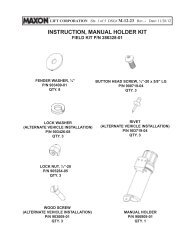
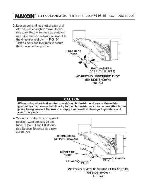
3. Loosen bolt and lock nut at each end<br />
of tube, just enough to move <strong>Underride</strong><br />
tube. Rotate the tube up or down,<br />
and slide the tube outward or inward to<br />
the dimensions shown in FIG. 5-1.<br />
Tighten bolts and lock nuts to secure<br />
the tube in correct position.<br />
UNDERRIDE<br />
TUBE<br />
BOLT, WASHER &<br />
LOCK NUT (2 PLACES)<br />
ADJUSTING UNDERRIDE TUBE<br />
(RH SIDE SHOWN)<br />
FIG. 5-1<br />
CAUTION<br />
When using electrical welder to weld on <strong>Underride</strong>, make sure the welder<br />
ground lead is connected directly to the <strong>Underride</strong>, as close as possible to the<br />
place being welded. Failure to comply can result in damaged cylinders and<br />
electrical parts.<br />
4. When the <strong>Underride</strong> is in correct<br />
position, weld the fl ats on the<br />
tube, to the RH and LH <strong>Underride</strong><br />
Support Brackets as shown<br />
in FIG. 5-2.<br />
RH UNDERRIDE<br />
SUPPORT BRACKET<br />
FLAT<br />
UNDERRIDE<br />
TUBE<br />
2 PLACES<br />
1/4”<br />
1/4”<br />
2 PLACES<br />
WELDING FLATS TO SUPPORT BRACKETS<br />
(RH SIDE SHOWN)<br />
FIG. 5-2