MDUI - 4222 - Connection Details - IG002R02.pdf
MDUI - 4222 - Connection Details - IG002R02.pdf
MDUI - 4222 - Connection Details - IG002R02.pdf
You also want an ePaper? Increase the reach of your titles
YUMPU automatically turns print PDFs into web optimized ePapers that Google loves.
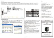
General<br />
The <strong>MDUI</strong> is a four port (3 RS-232 and 1 RS-422A) communications interface configured as 1 in and 3 out.<br />
Any one of the ports can be configured as the upstream port (primary), the remaining three ports are then downstream<br />
(secondary). An Aux RS-232 port is provided to enable diagnostic information to be accessed.<br />
RS-422A connections can be configured as single pair RS-485 connections by changing the jumper settings.<br />
The main uses of the <strong>MDUI</strong> include:<br />
1. Conversion between different comms protocols.<br />
2. To split individual RS-232 lines where multiple leased line modems are required for connection to remote sites.<br />
3. Galvanic isolation of segments of the JANUS comms line where there are differences in ground potential.<br />
4. To supervise and control two PCs in order to maintain a ‘Back-up’ system for live JANUS Comms. A <strong>MDUI</strong><br />
complete with supervisory software running on Windows NT will change over the JANUS Comms connections to a<br />
back-up PC should the main PC fail.<br />
Drive<br />
TX<br />
RX<br />
Fault<br />
Drive<br />
TX<br />
RX<br />
Fault<br />
Drive<br />
TX<br />
RX<br />
Fault<br />
Drive<br />
TX<br />
RX<br />
Fault<br />
Pulse<br />
Status LEDs<br />
Port 1<br />
Port 2<br />
Port 3<br />
Port 4<br />
P = F =<br />
1<br />
2<br />
3<br />
4<br />
Aux I/O<br />
Connector<br />
1<br />
8<br />
OFF<br />
AUX 4<br />
Transmit/Receive<br />
pin reverse jumpers<br />
ON<br />
Configuration Switches<br />
Diagnostic Port Comms Parameters<br />
Baud rate<br />
Data bits<br />
Stop bits<br />
Parity<br />
19200<br />
8<br />
1<br />
None<br />
(See note 5)<br />
Error Message Format<br />
CAS - Collision, data received simultaneously on more than one port<br />
SBM - Stop bit missing<br />
FSS - False start, very short duration noise pulse received.<br />
No port number will be given<br />
DCH - Data changed within one bit time window<br />
TOR - Transaction overrun, too many characters in transaction<br />
ICD - Illegal character detected<br />
RS-422A or RS-485<br />
selection jumpers<br />
Handshake<br />
jumpers<br />
(See note 6)<br />
Transmit/Receive<br />
pin reverse jumpers<br />
Line termination and<br />
screen connection<br />
jumpers<br />
RS-232 to RS-422A Converter<br />
<strong>MDUI</strong>-<strong>4222</strong><br />
TX-A<br />
TX-B<br />
RX-A<br />
RX-B<br />
SCRN<br />
(Port 3)<br />
2<br />
1<br />
Power Supply<br />
3<br />
2<br />
1<br />
- VE<br />
+ VE<br />
SCRN<br />
RX-B<br />
RX-A<br />
TX-B<br />
TX-A<br />
SCRN<br />
(8)<br />
(3)<br />
(2)<br />
(7)<br />
SCRN<br />
(8)<br />
(3)<br />
First IDC/IPC<br />
Upstream comms<br />
TX-A<br />
TX-B<br />
RX-A<br />
RX-B<br />
SCRN<br />
TX-A<br />
TX-B<br />
RX-A<br />
RX-B<br />
SCRN<br />
Downstream<br />
Comms<br />
Page 1 of 2<br />
(2)<br />
(7)<br />
OFF<br />
ON<br />
1<br />
Power Supply<br />
+12V<br />
GND<br />
(See note 3)<br />
PWR 4<br />
Line Termination<br />
(RS-422/485 Ports)<br />
SCRN<br />
RX-B<br />
RX-A<br />
TX-B<br />
TX-A<br />
SCRN<br />
RX-B<br />
RX-A<br />
TX-B<br />
TX-A<br />
RS-422A or RS-485<br />
Selection<br />
RS-485<br />
RS-422A<br />
RS-485<br />
RS-422A<br />
Jumper Settings<br />
RS-422A selected<br />
RS-485 selected<br />
Sw1 Switch Settings<br />
8<br />
Unused<br />
Unused<br />
Unused<br />
Pulse LED (See note 4)<br />
1200 Baud<br />
2400 Baud<br />
4800 Baud<br />
9600 Baud<br />
Port 1<br />
Port 2<br />
Port 3<br />
Port 4<br />
Screen <strong>Connection</strong><br />
(RS-422/485 Ports)<br />
SCRN<br />
RX-B<br />
RX-A<br />
TX-B<br />
TX-A<br />
SCRN<br />
RX-B<br />
RX-A<br />
TX-B<br />
TX-A<br />
Screen<br />
connected<br />
Screen<br />
broken<br />
Transmit/Receive<br />
pin reverse<br />
(RS-232 & diagnostic ports)<br />
Standard<br />
configuration<br />
TX/RX pins<br />
reversed<br />
Primary port<br />
selection<br />
Power<br />
from<br />
IDC PSU<br />
Battery<br />
Notes<br />
1. Status LEDs<br />
The transmit and receive of the primary and<br />
secondary ports will always be reversed.<br />
The red Fault LED indicates the respective port<br />
has been disabled. This occurs when error rate<br />
threshold is exceeded. All four Fault LEDs<br />
flashing indicates power supply low voltage.<br />
2. <strong>Connection</strong>s<br />
All RS-232 ports have the same configuration.<br />
A comms segment (maximum length of 1200M)<br />
remains part of the original comms line.<br />
Ports 1 & 2 can be connected using either the ‘D’<br />
type sockets or screen terminals.<br />
Screen connections on non-isolated ports (3 & 4)<br />
can be broken to remove earth loops.<br />
3. Power Supply<br />
A 1 Amp power supply is suitable for one or two<br />
<strong>MDUI</strong> boards, which can be fitted in a standard<br />
wall mounting enclosure. Connect the 0V power<br />
supply rail (Output - ) to chassis earth to provide<br />
a reference point.<br />
4. SW1/4<br />
Must be set to ON or the board will not run.<br />
5. Aux I/O Port<br />
Used for polling fail alarm.<br />
6. Handshake Jumpers<br />
These should not be set .<br />
IG002R02<br />
Multi-Drop Universal<br />
Interface <strong>4222</strong><br />
<strong>MDUI</strong>-<strong>4222</strong><br />
<strong>Connection</strong> <strong>Details</strong><br />
Grosvenor Technology Ltd, Millars Three,<br />
Southmill Road, Bishop’s Stortford,<br />
Hertfordshire. Tel: +44 (0)1279 838000<br />
grosvenortechnology.com
Typical Applications<br />
Leased Line Link<br />
Previous IDC/IPC<br />
Downstream comms<br />
TX-A<br />
TX-B<br />
RX-A<br />
RX-B<br />
SCRN<br />
TX-A<br />
TX-B<br />
RX-A<br />
RX-B<br />
SCRN<br />
<strong>MDUI</strong>-<strong>4222</strong><br />
(Port 3)<br />
TX-A<br />
TX-B<br />
RX-A<br />
RX-B<br />
SCRN<br />
Next <strong>MDUI</strong>-<strong>4222</strong><br />
(Port 4)<br />
Auto Changeover Configuration<br />
Network<br />
Server A<br />
Server B<br />
Com Port<br />
Com Port<br />
Server B<br />
<strong>MDUI</strong>-<strong>4222</strong><br />
(Port 3)<br />
TX-A<br />
TX-B<br />
RX-A<br />
RX-B<br />
SCRN<br />
(Port 2)<br />
First IDC/IPC<br />
Upstream Comms<br />
TX-A<br />
TX-B<br />
RX-A<br />
RX-B<br />
SCRN<br />
TX-A<br />
TX-B<br />
RX-A<br />
RX-B<br />
SCRN<br />
Modem<br />
Modem<br />
RS-232 Cables<br />
9 way D-type Male-Female<br />
pin to pin<br />
Leased Line<br />
Next IDC/IPC<br />
Upstream Comms<br />
(Port 1)<br />
Port 4 Port 3<br />
Port 2<br />
<strong>MDUI</strong>-<strong>4222</strong><br />
(Port 2)<br />
RS-422A<br />
RS-232<br />
From downstream port<br />
of previous IDC/IPC<br />
Modem<br />
TX-A<br />
TX-B<br />
RX-A<br />
RX-B<br />
SCRN<br />
<strong>MDUI</strong>-<strong>4222</strong><br />
(Port 3)<br />
TX-A<br />
TX-B<br />
RX-A<br />
RX-B<br />
SCRN<br />
TX-A<br />
TX-B<br />
RX-A<br />
RX-B<br />
SCRN<br />
Port 4<br />
Port 3<br />
Port 2<br />
RS-422A<br />
Server A<br />
To upstream port<br />
of first IDC/IPC<br />
Leased Line<br />
<strong>MDUI</strong>-<strong>4222</strong><br />
Port 1<br />
Modem<br />
RS-232<br />
<strong>MDUI</strong>-<strong>4222</strong><br />
Port 1<br />
To next <strong>MDUI</strong><br />
RS-232 Fibre Link<br />
Previous IDC/IPC<br />
Downstream comms<br />
Port 4 Port 3<br />
Port 2<br />
Port 1<br />
<strong>MDUI</strong>-<strong>4222</strong><br />
RS-422A<br />
RS-232<br />
TX-A<br />
TX-B<br />
RX-A<br />
RX-B<br />
SCRN<br />
From downstream port<br />
of previous IDC/IPC<br />
DVR-232/1 or 2xST<br />
Fibre Link<br />
TX-A<br />
TX-B<br />
RX-A<br />
RX-B<br />
SCRN<br />
RS-232<br />
To next <strong>MDUI</strong><br />
<strong>MDUI</strong>-<strong>4222</strong><br />
(Port 3)<br />
TX-A<br />
TX-B<br />
RX-A<br />
RX-B<br />
SCRN<br />
7<br />
2<br />
3<br />
8<br />
SCRN<br />
<strong>MDUI</strong>-<strong>4222</strong><br />
(Port 2)<br />
3<br />
2<br />
7<br />
Male<br />
TX<br />
RX<br />
SCRN<br />
DVR-232<br />
Fibre<br />
Link<br />
SCRN 7<br />
RX<br />
TX<br />
Male<br />
DVR-232<br />
2<br />
3<br />
Next <strong>MDUI</strong>-<strong>4222</strong><br />
(Port 4)<br />
2<br />
3<br />
5<br />
TX-A<br />
TX-B<br />
RX-A<br />
RX-B<br />
SCRN<br />
<strong>MDUI</strong>-<strong>4222</strong><br />
(Port 3)<br />
Next IDC/IPC<br />
Upstream Comms<br />
TX-A<br />
TX-B<br />
RX-A<br />
RX-B<br />
SCRN<br />
TX-A<br />
TX-B<br />
RX-A<br />
RX-B<br />
SCRN<br />
Page 2 of 2


