JANUS Engineering Training 0.4.pdf - Grostech.com
JANUS Engineering Training 0.4.pdf - Grostech.com
JANUS Engineering Training 0.4.pdf - Grostech.com
- No tags were found...

Create successful ePaper yourself
Turn your PDF publications into a flip-book with our unique Google optimized e-Paper software.
Level 1 - Hardware
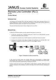
The Plan For Today<strong>JANUS</strong> ServerEthernet to RS485TCP/IP Directly onto ControllerLINE HEADERComms Line SegmentIDCe (Addr 1)Door CH1Reader CH1IDC485Addr ___Reader CH2Door CH2Door CH1Reader CH1Reader CH252
Readers Wiegand or Clock & DataSwipe Cards• Mag Swipe (Hotels – old credit cards)• A plastic card with a magnetic strip containing encoded data that is read by passingthe card through a usually slotted electronic deviceProximity (125kHz)• Contactless (Access Control)• Within the Proximity card an IC, capacitor, and coil are connected in parallel. The cardreader presents a field that excites the coil and charges the capacitor, which in turnenergizes and powers the IC. The IC then transmits the card number via the coil to thecard reader. The card readers <strong>com</strong>municate in Wiegand Protocol that consists of a data 0and a data 1 circuit.SMART 13.56mHz (MiFare / iClass / Legic / Indala / Deister etc)• Contactless (Access control / Cashless Vending)— Card• Contact― Chip and PIN― The Contactless chip <strong>com</strong>municates with the card reader through RFID induction technology.Like smart cards with contacts, contactless cards do not have a battery. The card readerpresents a field that excites the coil and charges the capacitor, which in turn energizes andpowers the card’s electronics. Data can be read and written.7Pulse Stretchers RDR-INT-PULSESTR• Allows non GTL format readers to be used on an IDC• Symptoms:• One read in 5 / 10 reads of a valid card will not allow access• Comms - View - Line Controller - Line - Box – DUMP• Same number of bits should be displayed each time the same card is presented• For each IDC only 1 x RDR-INT-PULSESTR is required73
IDC - 1 Door ConfigIDC - 2 Door Config• 2 x Readers (1 Door IN and OUT)• + 6 x Alarm Inputs• + 4 x Relay Outputs• + Tamper Circuit for Enclosure• 2 x Readers (2 x Doors)• + 6 x Alarm Inputs• + 4 x Relay Outputs• + Tamper Circuit forEnclosureKeypad either built in to reader or via PIN-INT-12-KEYEmergency Break GlassRelease lock– Use Dual Pole – Break +ve and –ve (Fail open locks)Keypad either built in to reader or via PIN-INT-12-KEYEmergency Break GlassRelease lock – Use Dual Pole – Break +ve and –ve (Fail open locks)894
Example Naming ConventionsLONDON Grosvenor HouseLGHPOOLE Blandford HousePBHLGH:01:10.0.0.1LGH ServerLGH:01:e:Gnd FloorLGH:01:LineLGH:01:01:Gnd FloorLGH:DG435:ReceptionLGH:DG435:Reception ININPUTOUTPUTPBH:D1435:OfficePBH:D1435:Office INPBH:D1435:Office OUTOUTPUTINPUTLGH:i556:PIRLGH:o6645:LightsPBH:o6653:SounderPBH:i87655:PIR105
<strong>JANUS</strong> Controller Connectivity• LINE HEADER connects a <strong>JANUS</strong> Server to IDCs and IPCs• RS232 Converter• USB Converter• Ethernet Converter• SEGMENT - 1,200m length of Belden (2 or 4 wire)• COMMS LINE - Total length from LINE HEADER to last IDC/IPC• NODE is an IDC or an IPC (Controller / Box / Tin?)• A COMMS LINE may have 32 x Nodes - address range 1 to 63• A COMMS LINE may have multiple segments using a MDUI orGI485• IDC-485s/IPC-485s connect via RS485 (2-wire)/RS422 (4-wire)• IDCes / IPCes (eSeries) connect via Ethernet (RJ45)connection ONLYRe<strong>com</strong>mended Cable Types• Line Header to IDC• 2 Pair Belden 1 #8723 1200m per Segment• Cat 5 – Use Twists – Not for electrically noisy environments – 200m• IDC to Reader• 4 Pair Belden 1 #9504 50m (If Using Keypad Interface)• Keypad to Keypad Interface• 4 Pair Belden 1 #9504 2m• Keypad Interface to IDC• 2 Pair Belden 1 #8723 50m• External Inputs• 2 Core Cable (Alarm) 100m• Locks• Use suitable gauge cable for current draw and volt dropCurrent Draw (Amps) x Distance (Meters) x Wire Resistance per Meter (Ohms) =Voltage Drop (Volts)1or equivalent12136
Intelligent Door Controller (IDC)• The Intelligent Door Controller(Multi-drop RS485 or TCP/IP available)• 2 readers with PIN - 1 or 2 door configuration• Additional 6 alarm inputs and 4 relay outputs• 12,288 /65,280 1 users at controller 2• AES Encryption on eSeries• Real-time processing at door• 2A power supply with battery back-up• Local LED and sounder outputs• Memory buffer whilst off-line (4,000 Events)• Upgrade flash whilst system is working• Any modern reader technology1 6144/ 55,296 With Custom PIN option firmware2 With memory expansion (Issue 9 / 10 IDC only)157
IDC-485 Connections IDC-485-6/4IDC-E-6/4 Connections IDC-E-6/4• Comms : RS485 or RS422• Address 1 to 63• SW1 – 1 & 2 Line Speed• SW1 – 3 to 8 Address (8=1, 3=32)• 2A at 12v available for locks / readers• Comms Chips RS 540-3921• Comms : Ethernet (RJ45) Only• Is its Own Line Header• Address 1 On Line• SW1-1 used to reset IP config• SW1- 2 to 8 spare• 2A at 12v available for locks /readersLEDs• RUN CPU Running• COMMS TX• ENG1 Comms Traffic on line• ENG2 Build Packet• ENG3 Mains Status• ENG4 See Documentation• Lock Pwr Lock Power StatusSee documentation for remaining LEDs16• Issue 1 version 2LEDs• RUN CPU Running• ENG1 Comms Traffic (RX)• ENG2 Build Packet (TX)• ENG3 Mains Status• ENG4 See Documentation• ENG5 X Port Status• ENG6 X Port Status• ONLINE <strong>JANUS</strong> Comms Connected• Lock Pwr Lock Power StatusSee documentation for remaining LEDs178
Reader and Lock WiringIDC-485 History• Issue 10 IDC-485-6/42001 - To date 6 x Inputs / 4 Outputs. Flash Firmware• Issue 91997 - 2001 4 x Inputs / 4 Outputs. Flash Firmware• Issue 8> 1994 - 1997 4 x Inputs / 4 Outputs EPROM Firmware• Orange connectors = <strong>JANUS</strong> DOS(Works on windows with Updated Firmware chip)• So. . .Issue 10 is6 x Inputs 4 x OutputsIssue 9 and earlier is 4 x Inputs 4 x OutputsIssue 8 and below EPROM firmwareDry Relay Output IDC-RLY-LCK-INT18199
Intelligent Peripheral Controller (IPC)The Intelligent Peripheral Controller (IPC)(Multi-drop RS485 or TCP/IP (e) available)• 16 Supervised Alarm Inputs• 16 Change-Over Relay Outputs• AES Encryption (eSeries)• Upgrade Flash whilst System is Operating• IPC-485-16/16 (RS485 – 422)• IPC-E-16/16 (Ethernet)NB: If box reports Tamper (where 16 inputs are used andinputs are not monitored) when enclosure is closed, install a300ohm resistor in series with input 12010
<strong>JANUS</strong> Enclosure ENC-20-PSU-230VSingle Board Enclosure• 1 x IDC or IPC Board• 1 x 7Ah Battery• Built in tamper to lid• Built in Power Supply with 2A available for externalequipment, i.e. locks and readers2111
<strong>JANUS</strong> 5-Way Enclosure ENC-5WAY-230V• 5-Way Enclosure - ENC-5WAY-230V• Blades for 5-Way enclosure - ENC-BLADE-20-PSU (IDC / IPC sold separately)• Blade + 12v Switch - ENC-BLADE-ENET• Must be installed using Uni Strut(unit is HEAVY)• Transformer built in• Fused internally at 3A• Space for 5 x 12v 7Ah Batteries• Side / rear / top low voltage cable entries• Side / rear mains supply entriesBlades ENC-BLADE-20-PSU / ENC-BLADE-ENETBlades for 5-Way enclosure• ENC-BLADE-20-PSU(IDCs / IPCs sold separately)Blade with Ethernet Switch• ENC-BLADE-ENET• Enclosure will hold5 x Blades222312
Comms WiringComms Lines Outside• A 485/422 <strong>com</strong>ms line is only ever grounded at ONE END between nodes• Each node on a segment must share a <strong>com</strong>mon building ground• If a <strong>com</strong>mon ground is not available then Galvanic Isolation should be employedbetween different earth potentials, otherwise <strong>com</strong>ms problems may arise• If cables run externally, Lightning Arrestors should be installed where the cablesenter and exit the building. Galvanic Isolation should then be used between theLightning Arrestor and IDC• Underground cable runs do not require Lightning ArrestorsAlternatively use TCP/IP or Fibre272814
Install <strong>JANUS</strong> 4.3r1• Auto run the Install software from the USB Stick• Install the MAIN PC and select MAIN PC• Say yes to Graphics and No to windows account synchronisation.• Load the licence file from the LIC folder from the USB Device• Restart the PC• Plug in the Dongle• Run:• <strong>JANUS</strong> COMMS• <strong>JANUS</strong> DATABASE• <strong>JANUS</strong> REPORT SCREEN (SCROLL)•Get the MAC and Serial from your Board. Using the eSeries Programmer configure your LH-ENET-485 and IDCe•Test the connectionsEngineer Logon:username : INSTALLERpassword : <strong>JANUS</strong>•Get the IDC and IDCe Online313215
<strong>JANUS</strong> Comms ProgramGREENMEENZCHOICESNever type into a green box!• Heart of the <strong>JANUS</strong> system• Must have access to the dongle and .gtl file to licence• Runs the MAIN PC (Server)• Only one Comms program should be running on a system• Can be run as a service• Is not used for general monitoring – good diagnostic tool.• Must run at CONSOLE level on Servers (/ADMIN now replaces/CONSOLE on MSTSC for VISTA and XP SP3)• Must logon at Installer Level to interact (Control – Login)• Diagnostics:• States of Inputs / Outputs on Controllers• See raw Binary card data from reader• Upload and activate Controller Firmware• Force Controller Poll• Missed Poll Count for each controller.343516
<strong>JANUS</strong> Comms Program<strong>JANUS</strong> Comms ProgramBoard willcontinue tooperatenormallywhiledownloadingThe Reports window will showtraffic from the IDCs / IPCs andwhere it is being routed to.Dump of raw carddata from readerThe System window will show Databasetraffic and Comms information andwhere it is being routed to.36Real Time Data3717
<strong>JANUS</strong> Comms ProgramCreating a Comms LineNeed to be logged on;When a box is selectedand this button is pressedthe MP count will be resetand if the box is offline<strong>com</strong>ms will immediatelypoll the box.• Local Comms Port: PhysicalPort attached to Server (1-9)• Network Comms Port:Software accessible CommsPort• Local Modem: Modem• Ethernet Comms Server:Ethernet Line Header (Nonencrypted)• eSeries: IDCe and encryptedline headersNo need to be loggedon; MP count for allboxes on line reset• Missed Polls indicate <strong>com</strong>municationsproblems; check cables/<strong>com</strong>ms chips etc.• You would expect all the boxes on a line tohave roughly the same MP count.• A controller may affect the MP count ofother boxes on the line.Auxiliary Line Type: If because of a fault, acontroller cannot be contacted through theprimary route, another route canautomatically be initiated by the system.Two additional ports may be defined for anygiven Comms Line.Speed: Must match box speed.38Normally, fields in the Comms Line Record be<strong>com</strong>e available or remain greyed out depending uponchoices made. For example the Telephone Number field would only be<strong>com</strong>e available if Local Modem isselected as the Line Type. For clarity, the Comms Line Record shown here has all fields shown withoutbeing greyed out.3918
eSeries SetupEncrypted - eSeries must be seeded by dongle number for IDCe to <strong>com</strong>e onlineUnencrypted - Ethernet Comms Server (LH-ENET) no seed requiredSite Codes – Used With Redundant Comms programsWindows Server – MUST be Logged in at CONSOLE (admin) level4019
Ethernet Line HeaderIDCeIf No Site code then either no Dongle plugged in or you are notlogged on at Console Level (/console or /admin depending on OSversion)If a standard <strong>JANUS</strong> system then the dongle number will bedisplayed - if fail over is required then site codes are used - V4.3upIf No Site code then either no Dongle plugged in or you are notlogged on at Console Level (/console or /admin depending onOS version)If a standard <strong>JANUS</strong> system then the dongle number will bedisplayed - if fail over is required then site codes are used -V4.3 up414220
Connection Confirmation.TELNET IPADDRESS 3001This will only work if <strong>JANUS</strong> Commsis NOT connected to the deviceeSeries Devices use three network ports— 80,9999 and 3001To test the network connections you can:Ping the device—PING IPADDRESSTelnet to Comms Port—TELNET IPADDRESS 3001—LED should illuminateTelnet to Configuration Port—TELNET IPADDRESS 9999—you should see:eSeries Devices IP ADDRESS ____.____.____.____Port 3001 test pass?Port 9999 test pass?LH Devices IP ADDRESS ____.____.____.____Port 3001 test pass?Port 9999 test pass?4321
Box (Controller)IDC Card Capacity IDC-MEM-UPG-65KName the BOXBox address (1 - 63)Max 32 on each lineLineDoor or I/ONormal BoxReportingEnter a descriptionof where thisController/Box isphysically located.This field is providedto assist futuremaintenanceengineers to locatethe Controller/Box.eSeries Devices; ADDRESS 1 insoftware but DO NOT addressboard. Leave all 8 DOWN.Poll Box - Click in the Poll Box field if you want the Controller/Box to be polled by the system.This feature is used to pre-define the system software before the hardware is installed. If thePoll Box field is not selected, 'Off-Line' alarms will be inhibited making the <strong>com</strong>missioningprocess easier to manage.• The IDC holds cards that have access to its readers inonboard volatile memory. There is space for just over 12,288cards• If User Definable PINs are required, special firmware needs tobe loaded into the IDC. This will restrict the number of cardsat the IDC to 6,144• To increase the number of cards available at a box, fitmemory expansion (Power the Board down first)• IDC Total cards: 65,280 (User Definable Pin – 55,296)454622
IDC - 2 Door ConfigIDC - 1 Door Config• 2 x Readers (2 x Doors)• + 6 x Alarm Inputs• + 4 x Relay Outputs• + Tamper Circuit forEnclosure• 2 x Readers (1 Door IN and OUT)• + 6 x Alarm Inputs• + 4 x Relay Outputs• + Tamper Circuit for EnclosureKeypad either built in to reader or via PIN-INT-12-KEYEmergency Break GlassRelease lock – Use Dual Pole – Break +ve and –ve (Fail open locks)Keypad either built in to reader or via PIN-INT-12-KEYEmergency Break GlassRelease lock– Use Dual Pole – Break +ve and –ve (Fail open locks)484923
DoorReaderName the doorChoose IDCTime door is unlockedafter valid card etc(default – 5 seconds)Name the ReaderChoose the boxIf card record ismarked Extendedunlock door byfactor of 2Door Ch1 or Ch2Door Contact Fitted?Report Forced?Two (IN / OUT) Readers?Interlock two doors on thisIDC?Time after legal open todeem wedged(default – 30 seconds)If the door contact is openfor this time deem faultyContinuous = NeverReader pluggedinto Ch1 or CH2Reader to controlLock Ch1 or Ch2Reader Group ForAccessIn conjunction withthe Door recorddefines sounderoutput.Cont = Continuous2s = 2 Seconds1m3s = 1 Minute 3SecondsApply lock power whendoor contact shows opensafter valid read / rte etc?Resistors installed to DoorContact?OPG – For linking to actions (F2)Usually ‘Normal Door Reporting’Defines where door events aresent. (F2)In <strong>com</strong>bination withReader Record controlsSNDR outputSee Note 1See Anti-PassbackOpens Access Rights Grid showing only the Reader Groups assigned to this reader.Defines if a Keypadis installed andwhen a PIN isrequired. Timeoutdefines how longthe user has toenter PIN. (F2)Normally ‘Normal Reader Reporting’2nd Rdr Group - This field is used for high security doors where two card holders must be valid at the reader before the Door will unlock. (Two differentReader Groups OR same Reader Group)Escort Reader - When an Escorted Card is seen at Escort Reader it requires a Host Card to also be presented before granting access (Same Reader Groups)2nd Read Only Authorises – The second card is not access granted – just authorises access for the first card.505224
Explaining Card AccessThe card can access any Readers in the COMMONDOORS reader group Mon – Fri 08:00 to 18:00.The Card has no access to Readers in the R&D orSupport Reader Groups.5125
CardsCard<strong>JANUS</strong> reads the whole card number including site code. The way the cardis read is defined by the Reader Type in the reader record and the firmwareversion in the IDC.For example:A card has a Site Code of 00502 and a Card Number of 0005001.<strong>JANUS</strong> would interpret this number as 5020005001.This means that <strong>JANUS</strong> will read multiple site codes so you do not needcards of the same Site Code on site, just the correct format.Card HolderDetailsCard DesignValid 1CustomerDefinedUsually Blank(Trace card)Card NumberGet NumberPIN Number 2Assigned AccessGroupsEdit Access Tablefor AssignedAccess RightsDon’t enforceAntiPassback4 times thelock time 4Dual ReaderGroups 4Date and TimesFree Text541: Valid will allow access, any other value will prevent access. You may select from the drop down or type your own reason.2: Two options; 1: System Generated – Standard IDC Firmware (choose from drop down list) 2: User Defined – PIN option IDC Firmware –Choose own 4 digit PIN ( Reduces card capacity in box)3: Opens a Dialog box that will show any unknown card (i.e. not already Programmed) and the reader it was seen on. Select and OK to put thenumber in the Record.4: Dependent on Reader Record configuration.5426
InputOutputName the inputChoose IDCThe Input number connectedInput Reporting GroupInput Type 2Select Input ReportingCategory M (F2)How long the input is activebefore generating an alarmPIR: Minimum timebetween activations togenerate an alarm 2PIR: If the input remains inalarm for this time deemthe input to be faultySelect if input is normallyopenSelect if input has ResistorsfittedName the OutputChoose IDC /IPCOutput Number on BoardChoose OPGOutput Pulse lengthDescription the input will reportto the Comms when it isactivated / deactivated(i.e. OFF if Normally Closed)1 IDC Issue 10 has Auxiliary Inputs, IDC Issue 9 and previous has 4 Auxiliary Inputs, IDC-Lite has 1 Auxiliary Input.2 Normal (Re<strong>com</strong>mended), PIR detector (Reports once every 30s after initial trigger or Aux 1 Period if set), Output pulse when triggered (If Input 1 willtrigger output 1 for 1 second (fixed) Limited)Normal Input ReportingIDC 6/4 has 4 Auxiliary outputsIDC-Lite has No Auxiliary OutputsIPC 16/16 has 16 Auxiliary OutputsIPC 16/4 has 4 Auxiliary Outputs (No Longer Supported)IPC32/24 has 24 Auxiliary Outputs (No Longer Supported)5556Actions – Linking Inputs to Outputs• The input has an Input Group of ‘BS PIR IPG’.• The action will use the ‘BS PIR IPG’ input group as the trigger to the Output Group ‘BS Alarm OPG’ as long asthe Mode is on and the timezone is active.• The output ‘BS Alarm Bell’ will turn on when the action turns on the ‘BS Alarm OPG’• You can have multiple inputs with the same Input Group and multiple outputs with the same Output Group.2757
Janus Report ScrollWhere a card was last badgedList the cards inan areaControl Output –On – Off and PulseList ‘not normal’itemsAcknowledge alarmsControl Modes –change access andreporting, etcControl Doors – Unlock –Relock and Momentary6228
Calling SupportWhen calling Support you will be asked for your Dongle (Serial) number. You can find this:• At the top of the <strong>JANUS</strong> Comms window• At the bottom of the <strong>JANUS</strong> Database Update windowYou will be given a Call Reference Number – you will need this if you call back so pleasehave a pen and paper ready• Support Phone Number: +44 (0)1279 838000• Support email: support@gtl.biz• Support website: www.grostech.<strong>com</strong>• Support FTP: ftp.grostech.<strong>com</strong>— Username and password required6329
Getting a Door Working1. <strong>JANUS</strong> DATABASE• Program the Comms Line• Program the Box2. <strong>JANUS</strong> COMMS• Check Box is Online• Upgrade the Firmware in the box• Run Diagnostics3. <strong>JANUS</strong> DATABASE• Create Access Group• Create Reader Group• Link Access Groups to Reader Groups• Create the Door• Create the readers (IN/OUT or IN)• HID PROX WIEGAND• Check D0 & D1 Correct4. SCROLL SCREEN• Control Door?• Door / Reader Monitoring?5. <strong>JANUS</strong> DATABASE• Program a card6. TEST CARD• Valid Access?• Watch Scroll screen• Look in Comms (Reports)6430