Remote Line Controller (RLC) - Grostech.com
Remote Line Controller (RLC) - Grostech.com
Remote Line Controller (RLC) - Grostech.com

Create successful ePaper yourself
Turn your PDF publications into a flip-book with our unique Google optimized e-Paper software.
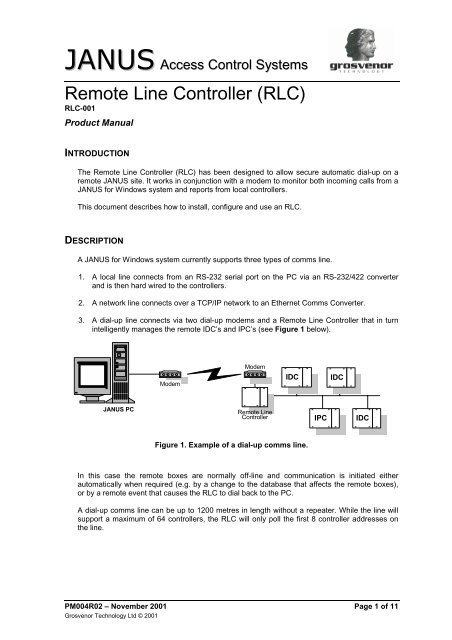
JANUS Access Control Systems<br />
<strong>Remote</strong> <strong>Line</strong> <strong>Controller</strong> (<strong>RLC</strong>)<br />
<strong>RLC</strong>-001<br />
Product Manual<br />
INTRODUCTION<br />
The <strong>Remote</strong> <strong>Line</strong> <strong>Controller</strong> (<strong>RLC</strong>) has been designed to allow secure automatic dial-up on a<br />
remote JANUS site. It works in conjunction with a modem to monitor both in<strong>com</strong>ing calls from a<br />
JANUS for Windows system and reports from local controllers.<br />
This document describes how to install, configure and use an <strong>RLC</strong>.<br />
DESCRIPTION<br />
A JANUS for Windows system currently supports three types of <strong>com</strong>ms line.<br />
1. A local line connects from an RS-232 serial port on the PC via an RS-232/422 converter<br />
and is then hard wired to the controllers.<br />
2. A network line connects over a TCP/IP network to an Ethernet Comms Converter.<br />
3. A dial-up line connects via two dial-up modems and a <strong>Remote</strong> <strong>Line</strong> <strong>Controller</strong> that in turn<br />
intelligently manages the remote IDC’s and IPC’s (see Figure 1 below).<br />
Modem<br />
Modem<br />
IDC<br />
IDC<br />
JANUS PC<br />
<strong>Remote</strong> <strong>Line</strong><br />
<strong>Controller</strong><br />
IPC<br />
IDC<br />
Figure 1. Example of a dial-up <strong>com</strong>ms line.<br />
In this case the remote boxes are normally off-line and <strong>com</strong>munication is initiated either<br />
automatically when required (e.g. by a change to the database that affects the remote boxes),<br />
or by a remote event that causes the <strong>RLC</strong> to dial back to the PC.<br />
A dial-up <strong>com</strong>ms line can be up to 1200 metres in length without a repeater. While the line will<br />
support a maximum of 64 controllers, the <strong>RLC</strong> will only poll the first 8 controller addresses on<br />
the line.<br />
PM004R02 – November 2001 Page 1 of 11<br />
Grosvenor Technology Ltd © 2001
<strong>Remote</strong> <strong>Line</strong> <strong>Controller</strong> (<strong>RLC</strong>)<br />
Product Manual<br />
<strong>RLC</strong> Features<br />
Answers calls from the JANUS system<br />
The <strong>RLC</strong> monitors the modem, if a call is received, the <strong>RLC</strong> will check that it is connected to the<br />
correct JANUS for Windows system. When this is established, it connects the controllers to the<br />
line for automatic transfer of information.<br />
Makes automatic calls to the JANUS system<br />
The <strong>RLC</strong> polls the first eight controller addresses on the <strong>com</strong>ms line, for information on what is<br />
happening on the remote site. If one of the events listed below occurs, the <strong>RLC</strong> connects itself<br />
to the JANUS for Windows system. After providing security and line information, the controllers<br />
are connected for automatic transfer of information.<br />
Compulsory dial-up from the remote site occurs if:<br />
<br />
<br />
<br />
<br />
<br />
<br />
<br />
<br />
<br />
<br />
A controller goes off-line from the <strong>RLC</strong><br />
A controller requests a config reset<br />
A controller event buffer is nearly full<br />
A controller mains power supply fails<br />
A controller has a tamper or lock power fail<br />
A duress pin occurs<br />
An input tamper occurs<br />
An <strong>RLC</strong> tamper occurs<br />
The <strong>RLC</strong> is powered-up<br />
Low battery voltage is detected for the <strong>RLC</strong><br />
Optional dial-up from the remote site occurs if:<br />
A programmed output group triggers a connection. This can be initiated by an action (the action<br />
would normally take place on activation of an input).<br />
Other features<br />
The <strong>RLC</strong> will attempt to connect to the JANUS for Windows system every minute until it<br />
achieves connection.<br />
Anti-passback and action information is controlled by the <strong>RLC</strong> during periods whilst it is<br />
disconnected from the Main JANUS for Windows site.<br />
The standard controller metal enclosure, PSU and battery backup can be used if wall<br />
mounting. Alternatively, the MDUI, modem-type euro enclosure can be used for desk or<br />
shelf mounting.<br />
The <strong>RLC</strong> can be upgraded by download from the JANUS system in the same way that<br />
an IDC issue 9 board can.<br />
Page 2 of 11 PM004R02 – November 2001<br />
Grosvenor Technology Ltd © 2001
Product Manual<br />
<strong>Remote</strong> <strong>Line</strong> <strong>Controller</strong> (<strong>RLC</strong>)<br />
INSTALLATION<br />
The installation requirements for an <strong>RLC</strong> are listed in Table 1.<br />
Description<br />
Part Number<br />
1 x Modem c/w chassis back-plate MDM-CHASSIS-001<br />
1 x <strong>Remote</strong> <strong>Line</strong> <strong>Controller</strong> (Mounts on chassis back-plate <strong>RLC</strong>-001<br />
with modem)<br />
1 x Enclosure (wall mounting, or modem type) IDC-ENC-WHI<br />
AUX-ENC-GRY<br />
1 x Power supply IDC-10-PSU<br />
1 x Battery. Typically 7Ah<br />
1 x Direct dial telephone point<br />
1 x 230V power source<br />
1 x Modem at main site (May already exist) MDM-USRB-CRR<br />
JANUS for Windows V2.40<br />
Box firmware dated on or after 09/12/98 (only required for<br />
auto-dialup and distribution of APB and Action information)<br />
Table 1. <strong>RLC</strong> installation requirements.<br />
The Modem requires 12V AC (separate power supply included with MDM-CHASSIS-<br />
001) and therefore can not be maintained with a battery.<br />
EMC Compatibility<br />
In order to <strong>com</strong>ply with the EMC Directive 89/336/EEC the following installation practices must<br />
be adhered to:-<br />
<br />
<br />
<br />
<br />
<br />
<br />
<br />
Use screened cable for all <strong>com</strong>munications connections, Belden #8723 or equivalent.<br />
Keep all cable runs as short and as neat as possible, particularly inside the enclosure<br />
where it is re<strong>com</strong>mended to route the cables around the main PCB thus avoiding laying the<br />
cables on the low voltage circuits.<br />
Do not route the cables near high voltages or strong magnetic fields<br />
Ensure that the 0v power supply connection is connected to earth<br />
Ensure the enclosure is connected to a reliable ground, an earthing stud is provided for this<br />
purpose in the wall mounting enclosure and ¼” tags are provided inside the desktop<br />
enclosure.<br />
Ensure that the enclosure lids are connected to chassis ground and that they are<br />
sufficiently secured once the installation is <strong>com</strong>plete. Panel gaps should be kept to a<br />
minimum<br />
Do not remove any more panel ‘knockouts’ than is necessary to <strong>com</strong>plete the wiring<br />
installation.<br />
Safety<br />
All equipment must be installed to meet Health and Safety requirements and the IEE 16 th edition<br />
of regulations for electrical installations. In particular, all enclosures must be securely connected<br />
to a reliable ground. Earth studs are provided in the wall mounting enclosure and earthing tags<br />
are provided in the free-standing enclosure for this purpose.<br />
PM004R02 – November 2001 Page 3 of 11<br />
Grosvenor Technology Ltd © 2001
<strong>Remote</strong> <strong>Line</strong> <strong>Controller</strong> (<strong>RLC</strong>)<br />
Product Manual<br />
Workmanship<br />
All wiring should be identified. The use of consistent cable types and colours for each element<br />
of the system will greatly ease system maintenance and future expansion.<br />
It is of vital importance to accurately label the installation and to provide detailed ‘as-installed’<br />
wiring drawings. Future maintenance and expansion of the system will depend on this<br />
information.<br />
Enclosure<br />
One <strong>RLC</strong> can be mounted vertically in the standard wall mounting enclosure with an IDC and<br />
power supply, or with a modem and power supply. Alternatively, a custom designed low-profile<br />
desk mounting enclosure is available.<br />
The enclosure should be installed in a secure area to prevent <strong>com</strong>promise of the system. The<br />
wall-mounting box may also be mounted horizontally if required. In all situations, sufficient<br />
space should be allowed to permit engineers to work inside the enclosures for future<br />
maintenance.<br />
The <strong>RLC</strong> should be installed in a clean dry area. It will work satisfactorily between a<br />
temperature of 0 degrees and 50 degrees centigrade with a relative humidity between 5% and<br />
85% and no condensation. The air should be <strong>com</strong>pletely free of corrosive gases<br />
Avoid strong magnetic fields generated by transformers and motors etc. Do not install the<br />
enclosures near to hazardous voltages or where they will be exposed to strong radio frequency<br />
signals.<br />
Power Supply<br />
If the <strong>RLC</strong> is fitted in a wall-mounting box then a standard 1 Amp power supply can be used.<br />
This is fitted in the same manner as for an IDC/IPC. Alternatively, if the <strong>RLC</strong> is mounted in the<br />
desktop enclosure then a separate plug-top power supply is available.<br />
It is re<strong>com</strong>mended that a standby battery be used. This is fitted in the wall mounting enclosure<br />
and is connected in the same way as for an IDC or IPC.<br />
Communications<br />
RS-422A <strong>com</strong>ms connections should be made with two individually shielded, twisted pairs (i.e.<br />
4 wires). All cable should be 22awg or larger, preferably stranded since it is less prone to<br />
damage during installation. Belden #8723 or it’s equivalent is re<strong>com</strong>mended.<br />
Page 4 of 11 PM004R02 – November 2001<br />
Grosvenor Technology Ltd © 2001
Product Manual<br />
<strong>Remote</strong> <strong>Line</strong> <strong>Controller</strong> (<strong>RLC</strong>)<br />
COMMISSIONING<br />
IDC/IPC Setup<br />
Currently the RS-422A <strong>com</strong>ms speed must be set to 4800 baud.<br />
Addresses should start at 1, any box with an address above 8 will NOT be polled by the <strong>RLC</strong>,<br />
and so cannot initiate dial-up or receive action/anti-passback packets. However, JANUS<br />
Comms can <strong>com</strong>municate with these boxes in the normal way when the link has been<br />
established.<br />
The Upstream/Downstream GND Select link on the IDC should be set to Downstream to<br />
ensure that only one end of each segment is grounded. See the Connection Details section for<br />
further information.<br />
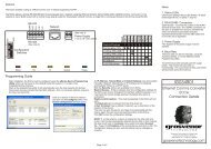
Board Layout<br />
The mounting holes must be connected to chassis earth via the mounting stud.<br />
Five way connector blocks are used for RS-422A connections, RS-232 connections are made<br />
via a standard 9 way ‘D’ connector mounted directly on the PCB.<br />
Status LEDs<br />
Jbus<br />
Pbus<br />
Run<br />
Pulse<br />
Eng1<br />
Eng2<br />
Mounting hole<br />
1. In (Red, PSU Load +ve)<br />
2. Sense (Blue, PSU LED)<br />
3. GND (Green, PSU Load -ve)<br />
Aux I/O Connector<br />
for future use<br />
Tamper Switch<br />
connector<br />
Power In<br />
+12V DC<br />
Modem connection<br />
2 - RxD<br />
3 - TxD<br />
4 - CTS<br />
5 - GND<br />
7 - RTS<br />
Pbus<br />
(For future use)<br />
Configuration Switches<br />
OFF ON<br />
1<br />
8<br />
SCRN<br />
RX-B<br />
RX-A<br />
TX-B<br />
TX-A<br />
Mounting hole<br />
Figure 2. <strong>RLC</strong> board layout (not to scale).<br />
An auxiliary I/O port has been provided for future development. No connection should<br />
be made to this port as it may cause irreversible damage to the <strong>RLC</strong>.<br />
PM004R02 – November 2001 Page 5 of 11<br />
Grosvenor Technology Ltd © 2001
<strong>Remote</strong> <strong>Line</strong> <strong>Controller</strong> (<strong>RLC</strong>)<br />
Product Manual<br />
Configuration switch settings<br />
The 8-way dip switch is used to make changes to the operational settings of the <strong>RLC</strong>.<br />
Switch # Default Operation<br />
Setting<br />
1 ON <strong>Line</strong> termination and failsafe resistors are activated.<br />
2 ON <strong>Line</strong> termination and failsafe resistors are activated.<br />
3 ON <strong>Line</strong> termination and failsafe resistors are activated.<br />
4 ON <strong>Line</strong> termination and failsafe resistors are activated.<br />
5 OFF Comms Protocol. OFF for RS-422A, ON for RS-485<br />
(not supported at this time).<br />
6 ON Pbus termination.<br />
7 ON Pbus termination.<br />
8 OFF Clear configuration. With the <strong>RLC</strong> powered, momentarily<br />
move this switch to the ON position to clear the<br />
configuration. JANUS Comms will need to connect and<br />
download new information before the <strong>RLC</strong> will operate.<br />
Table 2. Configuration switch settings.<br />
Please note that the switch settings are only read when the power is first connected<br />
to the <strong>RLC</strong>. Thus, when changes are made to the settings the <strong>RLC</strong> will need to be<br />
switched off and re-started before the changes take effect.<br />
Page 6 of 11 PM004R02 – November 2001<br />
Grosvenor Technology Ltd © 2001
Product Manual<br />
<strong>Remote</strong> <strong>Line</strong> <strong>Controller</strong> (<strong>RLC</strong>)<br />
Status LEDs<br />
Once the board is running the status can be monitored on the LEDs mounted on the front of the<br />
board. There are six LED’s, only five of which are currently used. See a description of each<br />
below.<br />
Jbus (yellow)<br />
This LED indicates the drive of the JANUS IDC/IPC <strong>com</strong>munications bus. This should be ON<br />
when using RS-422A.<br />
Pbus (yellow)<br />
This indicated the drive of the local Pbus. Normally OFF.<br />
Run (green)<br />
Indicated the main <strong>RLC</strong> processor is running. Normally ON.<br />
Pulse (green)<br />
Indicates the supervisory processor is running. Normally PULSING.<br />
Eng1 (red)<br />
Indicates any abnormal conditions. Normally OFF. The <strong>RLC</strong> will indicate a problem by flashing a<br />
code made up of a <strong>com</strong>bination of 8 long or short pulses. A long flash indicates a problem. By<br />
counting through the chain of 8 flashes and taking note of which are long, the problem can be<br />
determined. Table 3 below gives the meaning of each long flash.<br />
Flash # Problem<br />
1 <strong>RLC</strong> requires a reload (memory has been cleared)<br />
2 Can not establish <strong>com</strong>munications with modem<br />
3 Can not establish <strong>com</strong>munications with Jan<strong>com</strong>ms<br />
4 Lost <strong>com</strong>munications with an IDC/IPC (box off-line)<br />
5 Mains power to <strong>RLC</strong> has failed<br />
6 Battery voltage to <strong>RLC</strong> is low<br />
7 Unused<br />
8 Unused<br />
Table 3. Fault diagnosis.<br />
If Eng1 is on continuously, this indicates an internal fault.<br />
Eng2 (red)<br />
Not currently used. Normally OFF.<br />
PM004R02 – November 2001 Page 7 of 11<br />
Grosvenor Technology Ltd © 2001
<strong>Remote</strong> <strong>Line</strong> <strong>Controller</strong> (<strong>RLC</strong>)<br />
Product Manual<br />
CONNECTION DETAILS<br />
RS-232<br />
A 9 to 25-way cable is used to connect the modem to the RS-232 port on the <strong>RLC</strong>.<br />
RS-422A<br />
Connect the screen to the SCRN terminal at both ends and use the Upstream/Downstream<br />
GND select link on the IDC set to Downstream in order to ensure that only one end of each<br />
segment is grounded. See Figure 3 below. The SCRN terminal is grounded within the <strong>RLC</strong>.<br />
<strong>RLC</strong> Jbus RS-422<br />
TX-A<br />
TX-B<br />
RX-A<br />
RX-B<br />
SCRN<br />
First IDC<br />
RS-422 Comms<br />
Upstream Comms<br />
TX-A<br />
TX-B<br />
RX-A<br />
RX-B<br />
SCRN<br />
TX-A<br />
TX-B<br />
RX-A<br />
RX-B<br />
SCRN<br />
Downstream Comms<br />
Figure 3. RS-422A Connection details.<br />
All Further IDCs<br />
RS-422 Comms<br />
Upstream Comms<br />
TX-A<br />
TX-B<br />
RX-A<br />
RX-B<br />
SCRN<br />
TX-A<br />
TX-B<br />
RX-A<br />
RX-B<br />
SCRN<br />
Downstream Comms<br />
(To Upstream Port of Next IDC/IPC)<br />
When discussing JANUS <strong>com</strong>munications, the convention has been adopted that<br />
upstream is towards the host <strong>com</strong>puter and downstream is away from the host.<br />
Power Supply<br />
The power supply connections from the <strong>RLC</strong> should be taken from the OUTPUT + and<br />
OUTPUT - terminals on the PSU. Connection to the <strong>RLC</strong> is made via the Molex 3-pole<br />
connector on the board (see Figure 4). Care should be taken to ensure that polarity is not<br />
reversed. The OUTPUT - terminal of the power supply should also be grounded to the chassis<br />
earth via the mounting stud.<br />
<strong>RLC</strong> Power IN<br />
10-14V DC<br />
200mA<br />
+12V<br />
S<br />
GND<br />
Red<br />
Blue<br />
Green<br />
Molex 3-pole<br />
connector<br />
IDC PSU<br />
LED<br />
Figure 4. Power supply connections.<br />
Page 8 of 11 PM004R02 – November 2001<br />
Grosvenor Technology Ltd © 2001
Product Manual<br />
<strong>Remote</strong> <strong>Line</strong> <strong>Controller</strong> (<strong>RLC</strong>)<br />
CONFIGURING REMOTE LINE CONTROLLERS<br />
The <strong>RLC</strong> must be configured in the JANUS Database Update program. For full details, consult<br />
A Guide to Using JANUS for Windows by Grosvenor Technology Ltd.<br />
Three elements need to be set up on the JANUS system for the <strong>RLC</strong> to function:<br />
<br />
<br />
<br />
At least one modem should be defined.<br />
The <strong>com</strong>ms line must be defined as requiring a local modem.<br />
The <strong>RLC</strong> itself must be defined on the <strong>com</strong>ms line.<br />
1. In the JANUS Database Update program, click the mouse on Open · Hardware · <strong>Remote</strong><br />
<strong>Line</strong> <strong>Controller</strong>. The <strong>RLC</strong> dialog opens as shown in Figure 5.<br />
Figure 5. <strong>RLC</strong> dialog in JANUS Database Update program.<br />
2. To enter details of a new <strong>RLC</strong> click on the New button followed by the Choice button.<br />
Figure 6. Selecting line name for <strong>RLC</strong>.<br />
PM004R02 – November 2001 Page 9 of 11<br />
Grosvenor Technology Ltd © 2001
<strong>Remote</strong> <strong>Line</strong> <strong>Controller</strong> (<strong>RLC</strong>)<br />
Product Manual<br />
3. Select the <strong>Line</strong> Name to be used. Click OK.<br />
You must select a line that is defined as a Local Modem line.<br />
4. Type the telephone number that the <strong>RLC</strong> will need to dial to connect to the in<strong>com</strong>ing<br />
modem on the PC.<br />
5. With the cursor in the Trigger dial-up field, click on Choice.<br />
Figure 7. Select output group that will trigger dial-up.<br />
6. Select an Output Group, that will start the dial up when triggered. Click OK.<br />
7. With the cursor in the Reporting category field, click on the Choice button.<br />
Figure 8. Select reporting category.<br />
Page 10 of 11 PM004R02 – November 2001<br />
Grosvenor Technology Ltd © 2001
Product Manual<br />
<strong>Remote</strong> <strong>Line</strong> <strong>Controller</strong> (<strong>RLC</strong>)<br />
8. Select the name of the reporting category record that defines the messages you want from<br />
this <strong>RLC</strong>. Click OK.<br />
9. Select Save.<br />
You can define a new reporting category, either by clicking on the Add+ button in the<br />
Choice box, or by clicking on Open · Hardware · Box · Reporting.<br />
10. Repeat for each <strong>RLC</strong> to be configured.<br />
Millars Three, Southmill Road, Bishops Stortford, Herts, UK, CM23 3DH.<br />
Tel: +44 (0)1279 838000, email: sales@grosvenortechnology.<strong>com</strong>, web: grosvenortechnology.<strong>com</strong><br />
PM004R02 – November 2001 Page 11 of 11<br />
Grosvenor Technology Ltd © 2001