Remote Line Controller (RLC) - Grostech.com
Remote Line Controller (RLC) - Grostech.com
Remote Line Controller (RLC) - Grostech.com

You also want an ePaper? Increase the reach of your titles
YUMPU automatically turns print PDFs into web optimized ePapers that Google loves.
<strong>Remote</strong> <strong>Line</strong> <strong>Controller</strong> (<strong>RLC</strong>)<br />
Product Manual<br />
CONNECTION DETAILS<br />
RS-232<br />
A 9 to 25-way cable is used to connect the modem to the RS-232 port on the <strong>RLC</strong>.<br />
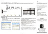
RS-422A<br />
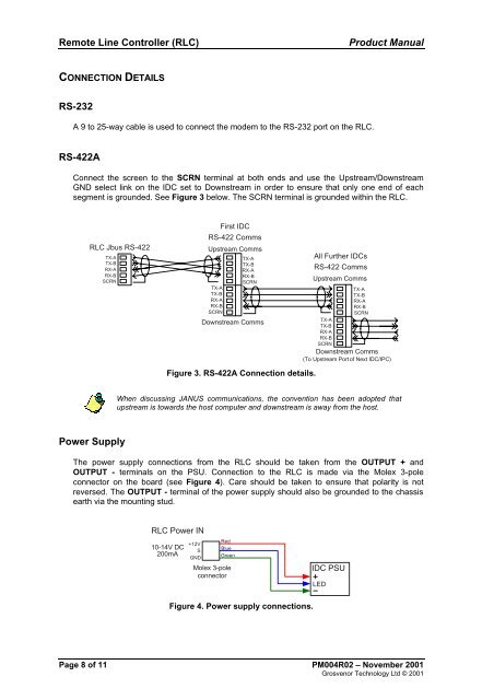
Connect the screen to the SCRN terminal at both ends and use the Upstream/Downstream<br />
GND select link on the IDC set to Downstream in order to ensure that only one end of each<br />
segment is grounded. See Figure 3 below. The SCRN terminal is grounded within the <strong>RLC</strong>.<br />
<strong>RLC</strong> Jbus RS-422<br />
TX-A<br />
TX-B<br />
RX-A<br />
RX-B<br />
SCRN<br />
First IDC<br />
RS-422 Comms<br />
Upstream Comms<br />
TX-A<br />
TX-B<br />
RX-A<br />
RX-B<br />
SCRN<br />
TX-A<br />
TX-B<br />
RX-A<br />
RX-B<br />
SCRN<br />
Downstream Comms<br />
Figure 3. RS-422A Connection details.<br />
All Further IDCs<br />
RS-422 Comms<br />
Upstream Comms<br />
TX-A<br />
TX-B<br />
RX-A<br />
RX-B<br />
SCRN<br />
TX-A<br />
TX-B<br />
RX-A<br />
RX-B<br />
SCRN<br />
Downstream Comms<br />
(To Upstream Port of Next IDC/IPC)<br />
When discussing JANUS <strong>com</strong>munications, the convention has been adopted that<br />
upstream is towards the host <strong>com</strong>puter and downstream is away from the host.<br />
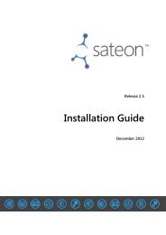
Power Supply<br />
The power supply connections from the <strong>RLC</strong> should be taken from the OUTPUT + and<br />
OUTPUT - terminals on the PSU. Connection to the <strong>RLC</strong> is made via the Molex 3-pole<br />
connector on the board (see Figure 4). Care should be taken to ensure that polarity is not<br />
reversed. The OUTPUT - terminal of the power supply should also be grounded to the chassis<br />
earth via the mounting stud.<br />
<strong>RLC</strong> Power IN<br />
10-14V DC<br />
200mA<br />
+12V<br />
S<br />
GND<br />
Red<br />
Blue<br />
Green<br />
Molex 3-pole<br />
connector<br />
IDC PSU<br />
LED<br />
Figure 4. Power supply connections.<br />
Page 8 of 11 PM004R02 – November 2001<br />
Grosvenor Technology Ltd © 2001