ParSec Data Display & Entry Panel (DDE ... - How do I
ParSec Data Display & Entry Panel (DDE ... - How do I
ParSec Data Display & Entry Panel (DDE ... - How do I

Create successful ePaper yourself
Turn your PDF publications into a flip-book with our unique Google optimized e-Paper software.
<strong>ParSec</strong><br />
<strong>Data</strong> <strong>Display</strong> &<br />
<strong>Entry</strong> <strong>Panel</strong> (<strong>DDE</strong>)<br />
INSTALLATION &<br />
USER MANUAL
This page is intentionally blank
<strong>ParSec</strong> <strong>Data</strong> <strong>Display</strong> & <strong>Entry</strong> <strong>Panel</strong> (<strong>DDE</strong>)<br />
INSTALLATION & USER MANUAL<br />
Part No: UM016<br />
Document No: A/UM 230 851<br />
Issue Draft 5<br />
August 2000<br />
Newmark Technology Ltd<br />
21-23, Ormside Way<br />
Redhill<br />
Surrey<br />
RH1 2NT<br />
United King<strong>do</strong>m<br />
Tel: +44(0) 1737 788800<br />
Fax: +44(0) 1737 779535<br />
Web site: www.newmarkworld.com<br />
<strong>DDE</strong> Installation & Operation Manual - Issue: 5 August 2000 - Page 1
FCC Compliance Statement<br />
These devices comply with part 15 of the FCC CFR 47 rules.<br />
Operation is subject to the following two conditions:<br />
(1) These devices may not cause harmful interference, and<br />
(2) These devices must accept interference received, including<br />
interference that may cause undesired operation.<br />
The user is cautioned that modifications or changes to an<br />
intentional or unintentional radiator not expressly approved by the<br />
party responsible for compliance could void the user's authority to<br />
operate the equipment.<br />
The <strong>DDE</strong> contains a standard Lithium coin cell and as such the<br />
following warning shall be noted:<br />
CAUTION<br />
Danger of explosion if batteries are incorrectly replaced.<br />
Replace only with the same or equivalent type recommended by<br />
the manufacturer. Dispose of used batteries according to the<br />
manufacturers instructions within this manual.<br />
IMPORTANT NOTE<br />
This manual should be read in conjunction with the <strong>ParSec</strong><br />
Reader manual IM016.<br />
<strong>DDE</strong> Installation & Operation Manual - Issue: 5 August 2000 - Page 2
CONTENTS<br />
1 Caution - Static Precautions<br />
2 General Installation & Guidance Notes<br />
2.1 <strong>DDE</strong> Function & Design<br />
2.2 Siting the <strong>DDE</strong><br />
2.3 Power Supply Requirements<br />
2.4 Communications Interface<br />
2.5 Alarm Contacts<br />
3 Installing the <strong>DDE</strong><br />
3.1 Fixing the Enclosure<br />
3.2 Wiring Connections<br />
3.3 Ferrite Cores<br />
3.4 Ferrite Installation and Wiring<br />
4 <strong>DDE</strong> Operation<br />
4.1 Pin Level 0 - Alarm Acknowledgement<br />
4.2 Pin Level 1 - Disable PAT's<br />
4.3 Pin Level 2 - Disable SAT's<br />
4.4 Pin Level 3 - Administration Level<br />
4.4.1 PAT Options<br />
4.4.2 SAT Options<br />
4.4.3 System Options<br />
4.4.4 Reset Options<br />
4.4.5 Print Options<br />
4.4.6 Alarm Options<br />
4.4.7 Change PIN Numbers<br />
5 Commissioning the system<br />
5.1 Power Up<br />
5.2 Default SAT Pulse Count<br />
5.3 Monitoring Mode<br />
5.4 Commissioning Procedure Summary<br />
<strong>DDE</strong> Installation & Operation Manual - Issue: 5 August 2000 - Page 3
6 Trouble shooting<br />
7 Repair<br />
6.1 System Self-test<br />
6.2 Tags Not Being Reported<br />
6.3 Loss of <strong>Data</strong><br />
8 Technical Specification<br />
9 Change Record<br />
<strong>DDE</strong> Installation & Operation Manual - Issue: 5 August 2000 - Page 4
1 CAUTION- STATIC PRECAUTIONS<br />
Some devices used within the <strong>DDE</strong> are sensitive to static electricity.<br />
Anti-static precautions must be taken when handling the printed circuit boards.<br />
Static discharge may permanently damage the boards. The damage<br />
may not be immediate, but could affect the performance and life of the<br />
unit.<br />
2 GENERAL INSTALLATION AND GUIDANCE NOTES<br />
2.1 <strong>DDE</strong> Function and Design<br />
Function<br />
The <strong>DDE</strong> is a microprocessor-controlled device and communicates up<br />
to 9-<strong>ParSec</strong> Readers via an RS-232 serial data port. The <strong>DDE</strong> includes<br />
a Centronics parallel printer port for a hard copy record of system<br />
events.<br />
The <strong>DDE</strong> panel has been designed for small to medium sized Asset<br />
Protection installation. Its memory capability will store up to 200 tags,<br />
portable (PAT's) and/or Static tags (SAT's).<br />
For larger installations, PC-based Asset management and Protection<br />
software is available. For further information contact Newmark<br />
Technology.<br />
The main purposes of the <strong>DDE</strong> panel in everyday use are to;<br />
1. Report alarm events.<br />
2. Facilitate the authorised removal from site and validate re-entry of<br />
PAT's.<br />
3. Permit enabling/disabling of SAT's to allow temporary movement of<br />
SAT- protected assets.<br />
The <strong>DDE</strong> also has the ability to individually adjust the motion sensitivity<br />
of each SAT within the system.<br />
Note:<br />
The <strong>DDE</strong> is not designed to recognise personnel tags (PET's).<br />
<strong>DDE</strong> Installation & Operation Manual - Issue: 5 August 2000 - Page 5
POWER<br />
ALARM<br />
1 2 3<br />
4 5 6<br />
7 8 9<br />
REJECT<br />
0<br />
ACCEPT<br />
Figure 1<br />
<strong>Data</strong> <strong>Display</strong> & <strong>Entry</strong> panel<br />
shown with front panel open & closed<br />
<strong>DDE</strong> Installation & Operation Manual - Issue: 5 August 2000 - Page 6
Design<br />
The <strong>DDE</strong> consists of a hinged all metal housing which provides<br />
protection and security to the internal Logic Printed Circuit Board (PCB).<br />
The front panel comprises a 2-line x 20 character back-lit LCD panel, on<br />
which alarms and status information are displayed, and a numeric<br />
membrane keypad for system configuration and tag control. The front<br />
panel also includes two LED's that indicate power on (green) and an<br />
alarm (red).<br />
The <strong>DDE</strong> front cover is normally supplied with standard M3 x 10mm<br />
long cross head screws, which may be replaced by security or “Torx”<br />
head screws. Newmark provide these alternative security screws with<br />
every unit. To use these alternative fixings you will require the following<br />
tools; “Torx” type TX10 screwdriver or a Newmark security driver (Part<br />
no SS0001).<br />
Any attempt to remove the front cover will operate the internal antitamper<br />
switch that may be used to trigger a local or remote alarm.<br />
The housing rear panel provides wall mounting points, cable entry holes<br />
and a chassis earth/ground point.<br />
The <strong>DDE</strong> logic PCB is mounted on the rear of the hinge-<strong>do</strong>wn front<br />
panel and permits easy access to the connection terminals and<br />
components for installation and maintenance.<br />
<strong>DDE</strong> Installation & Operation Manual - Issue: 5 August 2000 - Page 7
2.2 Siting the <strong>DDE</strong><br />
Caution<br />
Because the <strong>DDE</strong> is housed within a metal box, if mounted<br />
in close proximity to a <strong>ParSec</strong> reader it may affect the<br />
performance of that reader.<br />
The <strong>DDE</strong> will normally be sited in a secure area or for convenience near<br />
the exit, which is being monitored by <strong>ParSec</strong> Readers. To permit the<br />
logging out of tagged assets. It should be mounted at a convenient<br />
height to allow easy operation of the keypad in conjunction with a clear<br />
view of the LCD display.<br />
If you wish to use the PAT log-out facility whilst carrying the tagged<br />
asset, the <strong>DDE</strong> must be located outside the PAT Protected Reader<br />
zone to enable correct operation of the system.<br />
If the <strong>DDE</strong> is to be used purely for monitoring and the log-out facility is<br />
not required; the unit may be mounted in a location convenient to the<br />
designated administrator of the asset protection system.<br />
For an installation where there are multiple Readers, the <strong>DDE</strong> should be<br />
located in a conveniently central location.<br />
The <strong>DDE</strong> is screened and requires no special precautions for protection<br />
against electromagnetic interference, other than proper grounding.<br />
2.3 Power Supply Requirements<br />
The <strong>DDE</strong> requires a 12V/150mA, DC power supply, which must be CE<br />
or other local authority approved.<br />
Power to the <strong>DDE</strong> may optionally be derived from an adjacent <strong>ParSec</strong><br />
Reader, in which case use a suitable shielded cables e.g. 2-core Belden<br />
8760.<br />
It is recommended that power and signal cables to the <strong>DDE</strong> should be<br />
separated from 3-phase mains supplies by at least 1 metre and from<br />
single phase main supplies and all other types of cable runs by at least<br />
0.5 metres.<br />
The <strong>DDE</strong> is equipped with an internal lithium battery to protect the<br />
stored data for a period of one month. If power is removed from the<br />
<strong>DDE</strong> for longer than this all its data may be lost.<br />
<strong>DDE</strong> Installation & Operation Manual - Issue: 5 August 2000 - Page 8
2.4 Communications Interface<br />
Communication between the <strong>DDE</strong> and its associated <strong>ParSec</strong> Reader(s)<br />
is made via an RS-232 serial data link operating at 2400 baud. To<br />
comply with the RS-232 specification, the signal cable between the two<br />
devices should not be greater than 60 metres in length; in practice,<br />
greater lengths are often possible. Use 2-core Belden 8761, 9841 or<br />
9501. Always connect the screen to earth/ground at the remote end.<br />
2.5 Alarm Contacts<br />
The <strong>DDE</strong> panel has an internal audible alarm and relay contacts for<br />
connection to an external alarm device. The alarm is ‘fail safe’, i.e.<br />
during normal operation with no alarms activated, the relay is energised;<br />
the relay is de-energised when an alarm is generated. Use a suitable 2<br />
or 3-core shielded cable, e.g. Belden 9533.<br />
Terminal connections for the wiring of an external alarm are;<br />
TERMINAL 1<br />
Pin 6 - Relay Normally Open (when power is OFF).<br />
Pin 5 - Relay Common.<br />
Pin 4 - Relay Normally Closed (when power is OFF).<br />
<strong>DDE</strong> Installation & Operation Manual - Issue: 5 August 2000 - Page 9
This page is intentionally blank<br />
<strong>DDE</strong> Installation & Operation Manual - Issue: 5 August 2000 - Page 10
3 INSTALLING THE <strong>DDE</strong><br />
3.1 Fixing the <strong>DDE</strong> Enclosure<br />
The case should be fixed in position with appropriate screws (No 6 or<br />
No 8) in the upper two Keyhole mounting points, and secured with a<br />
third screw in the lower slotted hole. The location of the 3-cable entry<br />
holes (A) and the chassis earth point (B) must also be taken into<br />
consideration prior to permanently mounting the <strong>DDE</strong>.<br />
10<br />
31<br />
152<br />
90<br />
10<br />
42<br />
31<br />
11<br />
A<br />
210<br />
150<br />
127.5<br />
133<br />
A<br />
A<br />
B<br />
CABLE ENTRY<br />
HOLE 'A'<br />
IN 3 POS'NS<br />
45<br />
CHASSIS<br />
EARTH<br />
GROUND<br />
Figure 2 Fixing Details<br />
<strong>DDE</strong> Installation & Operation Manual - Issue: 5 August 2000 - Page 11
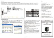
3.2 Wiring Connections<br />
The diagram below shows the <strong>DDE</strong> logic PCB and identifies its major<br />
components. The diagram depicts the PCB as viewed with the front<br />
panel hinged open, and shows the wiring connections to the three<br />
terminal blocks (Term 1-3).<br />
PL2<br />
Battery<br />
Tamper<br />
Switches<br />
S1<br />
S3<br />
S1 Reserved for<br />
future use<br />
3 - RS232 Ground<br />
2 - RS-232 Receive In<br />
1 - RS232 Transmit Out*<br />
2 - Power supply 0V<br />
1 - Power Supply + 12V<br />
Term3<br />
1<br />
Term2<br />
1<br />
Term1<br />
1<br />
S3<br />
8 Tamper<br />
Normally<br />
7 Tamper closed<br />
6 Relay NO (Power OFF)<br />
5 Relay C<br />
4 Relay NC (Power OFF)<br />
3 Reserved<br />
2 Ground<br />
1 Reserved<br />
EPROM<br />
Sounder<br />
* RS232 Transmit out ( used for self-test only. See section 6.1)<br />
FIGURE 3<br />
<strong>DDE</strong> LOGIC PCB LAYOUT & WIRING CONNECTION<br />
<strong>DDE</strong> Installation & Operation Manual - Issue: 5 August 2000 - Page 12
Term 2-6 (0V) Term 2-6 (0V) Term 2-6 (0V)<br />
Term 2-5 (Tx) Term 2-4 (Rx) Term 2-5 (Tx) Term 2-4 (Rx)<br />
Term 2-5 (Tx)<br />
Up to Reader 9 Reader 2 Reader 1<br />
Term 3-2 (Rx)<br />
Belden 8761,9841 or 9501<br />
Term 3-3 (0V)<br />
<strong>DDE</strong><br />
Optional <strong>DDE</strong> alarm relay<br />
and/or tamper switch<br />
connections to intruder alarm<br />
panel, beacon or sounder etc.<br />
Optional event printer (Dot-matrix)<br />
FIGURE 4<br />
<strong>DDE</strong> TO READER RS232 WIRING CONNECTIONS<br />
<strong>DDE</strong> Installation & Operation Manual - Issue: 5 August 2000 - Page 13
3.3 Ferrite Cores.<br />
WARNING<br />
The <strong>DDE</strong> is supplied with 3 cylindrical ferrite cores, these must be fitted<br />
to the cables entering or exiting the <strong>DDE</strong>. The Ferrite's are designed to<br />
reduce the amount of radiated EMC transmissions from the unit and<br />
MUST be fitted for it to conform to CE and FCC certification. Always<br />
install the <strong>DDE</strong> wiring in accordance with this section. Newmark<br />
Technology takes no responsibility for any unit installed incorrectly.<br />
Of the 3 ferrite's supplied, 2 are physically the same shape and size,<br />
these are used for the RS232 and RELAY contact cables prior to<br />
termination. The third ferrite, which is physically larger, is used for the<br />
entering POWER cable prior to termination.<br />
You will notice that there are 3 cable entry holes in the <strong>DDE</strong> rear<br />
chassis plate. When the unit is closed these holes correspond with the<br />
3 terminal locations on the <strong>DDE</strong> processor PCB. Adjacent to each PCB<br />
terminal is a threaded earth stud, which MUST be used to ground the<br />
cable screen to the <strong>DDE</strong> chassis. These cable screens must be kept as<br />
short as possible to obtain the best results.<br />
Cable-tie bases are situated inside the unit to aid the location and<br />
mounting the ferrite cores. Cable-ties have also been supplied to use<br />
for retaining the ferrite's and cables once fitted.<br />
IMPORTANT WIRING INFORMATION<br />
The individual conductors of each cable must be fed through the ferrite<br />
cores a number of times, this must be taken into account when<br />
providing enough cable and removal of the outer insulation sleeve.<br />
1. The POWER and RELAY conductor MUST pass 3 times through its<br />
ferrite core before termination.<br />
2. The RS232 DATA conductors MUST pass twice through its ferrite<br />
core before termination.<br />
3. The <strong>DDE</strong> unit chassis MUST be EARTHED.<br />
<strong>DDE</strong> Installation & Operation Manual - Issue: 5 August 2000 - Page 14
This page is intentionally blank<br />
<strong>DDE</strong> Installation & Operation Manual - Issue: 5 August 2000 - Page 15
3.4 Ferrite Installation and Wiring.<br />
Fitting the ferrite's (See figure 5 & 6).<br />
1. Feed the RS232 cable through the <strong>DDE</strong> chassis rear panel using the<br />
appropriate hole (in this case bottom Left-hand side). Ensure there is<br />
enough cable to reach terminal 3 and to feed through the ferrite core<br />
twice (RS232 ONLY).<br />
2. Strip back the outer insulating sleeve approx. 200mm (RS232<br />
ONLY).<br />
3. If your cable has an aluminium foil and shield drain wire, remove the<br />
foil back to the outer insulation.<br />
4. Twist the shield drain wire as tightly as possible and position the<br />
cable so that the stripped back insulated section is as close as<br />
possible to the relevant earth/ground stud.<br />
5. Wrap the shield drain wire around the stud and secure using the nut<br />
and washer provided. Once the cable is secure you can cut off the<br />
excess shield drain wire.<br />
Note: A suitable crimp or solder ring terminal can also be used to<br />
terminate this shield drain wire. Remember to keep the length of this<br />
wire as short as possible.<br />
6. Feed the remaining conductors through the ferrite core the correct<br />
number of times (in this case twice for RS232 cable).<br />
7. Fit the cable ties to the cable tie bases, but <strong>do</strong> not loop or interlock<br />
them.<br />
8. Place the ferrite between the two cable tie bases adjacent to terminal<br />
3 and adjust the cable by removing as much cable slack as possible<br />
from either side of the ferrite.<br />
9. Cut the individual conductors to the required length for termination.<br />
10.Strip back approx. 5-6mm of the conductor insulation and terminate<br />
the wires in accordance with section 3.2.<br />
11. Loop and interlock the cable ties on either side of the ferrite and<br />
secure the cable in place.<br />
12. Remove the loose ends of the cable ties.<br />
Repeat this procedure for the POWER and RELAY cables observing the<br />
cable length and correct number of cable loops in parts 2 and 6<br />
(3 times for POWER and RELAY cables).<br />
<strong>DDE</strong> Installation & Operation Manual - Issue: 5 August 2000 - Page 16
Loop individual<br />
conductors<br />
Screened cable<br />
Cable Tie &<br />
Cable screen<br />
earth stud<br />
Terminal<br />
Ferrite<br />
Core<br />
FIGURE 5<br />
TYPICAL FERRITE CORE INSTALLATION<br />
Chassis<br />
Earth<br />
Point<br />
PL2<br />
S1<br />
S3<br />
Earth Stud<br />
In 3 positions<br />
RS232<br />
Ferrite<br />
Core<br />
Power In<br />
Ferrite<br />
Core<br />
Term3<br />
(RS232)<br />
1<br />
Term2<br />
1<br />
(Power)<br />
Term1<br />
(Relay)<br />
1<br />
Relay<br />
Ferrite<br />
Core<br />
Cable Tie & Base<br />
In 6 positions<br />
FIGURE 6<br />
FERRITE CORE POSITION<br />
<strong>DDE</strong> Installation & Operation Manual - Issue: 5 August 2000 - Page 17
This page is intentionally blank<br />
<strong>DDE</strong> Installation & Operation Manual - Issue: 5 August 2000 - Page 18
4 <strong>DDE</strong> OPERATION<br />
General Notes & Conventions<br />
The <strong>DDE</strong> user interface comprises a numeric keypad 0-9 with an Accept<br />
and Reject key. Numeric keys 2, 4, 6 & 8 are dual function keys, bearing<br />
arrows for navigation around the user menu.<br />
1<br />
2<br />
3<br />
4 5 6<br />
7<br />
8<br />
9<br />
The LCD display provides user feedback in the form of menu functions<br />
and status reports. The arrow indicators shown on the display<br />
correspond with the dual function arrow keys on the numeric keypad.<br />
2<br />
REJECT<br />
0<br />
ACCEPT<br />
4<br />
8<br />
In the diagrammatic operating instructions within this section the<br />
following conventions are used.<br />
28-Mar-00 10:31<br />
Monitoring<br />
1234<br />
Accept<br />
6<br />
LCD text display<br />
indicates a key sequence should be entered<br />
indicates a particular arrow key should be pressed<br />
denotes normal logic flow<br />
denotes incorrect or invalid logic flow<br />
<strong>DDE</strong> Installation & Operation Manual - Issue: 5 August 2000 - Page 19
Access to all <strong>DDE</strong> functions is controlled by ‘PIN’ numbers, which are<br />
user-programmable. The unit is delivered with the following default PIN<br />
codes.<br />
• PIN level 0 - Alarm Acknowledgement 0001<br />
• PIN level 1 - Log out PAT 1111<br />
• PIN level 2 - Enable/disable SAT 2222<br />
• PIN level 3 - Administrator level 3333<br />
It is recommended for security reasons that the person assigned Administrator<br />
for the <strong>ParSec</strong> system should change the PIN codes to their own selection<br />
during the commissioning process which follows.<br />
Notes<br />
1. If at any time <strong>DDE</strong> is waiting for a key-press action, a 10-second<br />
time-out will come into effect. If the time-out occurs, the unit will in<br />
most cases revert back to the monitoring mode display.<br />
2. When monitoring, the first key-press is accepted as the first digit of<br />
a PIN number. PIN numbers are confirmed using the Accept key.<br />
3. Error messages are cleared by pressing any key, or by waiting for<br />
the unit to time-out.<br />
4.1 PIN Level 0 - Alarm Acknowledgement<br />
Default PIN = 0001<br />
This level acknowledges and clears an alarm; the alarm relay is reenergised<br />
(its default state) and the alarm LED is goes out. The <strong>DDE</strong><br />
reverts immediately to monitoring mode.<br />
<strong>DDE</strong> Installation & Operation Manual - Issue: 5 August 2000 - Page 20
4.2 PIN Level 1 - Disable PAT's [User Level]<br />
Default PIN = 1111<br />
This PIN level is used to disable or re-enable individual PAT's, to allow<br />
an authorised user to remove a tagged item from an area, and<br />
subsequently to bring the item back in, without causing an alarm.<br />
Upon entry of the PIN, any alarm sounding will be cleared.<br />
29-Mar-00 10:30<br />
Monitoring<br />
1111<br />
Accept<br />
Enable pat<br />
2 8<br />
6<br />
Disable pat 6<br />
Pat number<br />
Pat number<br />
24<br />
Accept<br />
24<br />
Accept<br />
No such tag<br />
No such tag<br />
4<br />
or timeout<br />
When the tag is next seen by a reader, a grace period of 5 minutes is<br />
initiated, following which an alarm will be generated if the tag is seen<br />
again by a reader.<br />
Notes<br />
1. Tamper alarms are always reported.<br />
<strong>DDE</strong> Installation & Operation Manual - Issue: 5 August 2000 - Page 21
4.3 PIN Level 2 – Disable SAT's<br />
Default PIN = 2222<br />
This level is used to disable and re-enable individual SAT's, when the<br />
asset protected by the SAT is to be moved, for example, for<br />
maintenance purposes.<br />
29-Mar-00 10:30<br />
Monitoring<br />
2222<br />
Accept<br />
enable sat<br />
2 8<br />
6<br />
disable sat 6<br />
Sat number<br />
Sat number<br />
24<br />
Accept<br />
24<br />
Accept<br />
no such tag<br />
no such tag<br />
4<br />
or timeout<br />
Note<br />
1. Tamper alarms are always reported, even if a SAT has been<br />
disabled.<br />
<strong>DDE</strong> Installation & Operation Manual - Issue: 5 August 2000 - Page 22
4.4 PIN Level 3 - Administration Level<br />
Default PIN = 3333<br />
This PIN is used to access all system functions (any alarm sounding will<br />
be cleared).<br />
print options<br />
alarm options<br />
logout options<br />
change pins<br />
29-Mar-00 10:31<br />
Monitoring<br />
3333<br />
Accept<br />
Status v3<br />
P-Y S-Y A-Y T=006<br />
pat options<br />
sat options<br />
system options<br />
reset options<br />
<strong>DDE</strong> Installation & Operation Manual - Issue: 5 August 2000 - Page 23
The system status is displayed, comprising<br />
• Software version number:<br />
Where X.X = The version of software fitted<br />
• PAT's, SAT's & Alarms enabled (disabled):<br />
V X.X<br />
P-Y S-Y A-Y<br />
For example;<br />
P-Y means all PAT's are enabled (Y = Yes, N = No).<br />
S-Y means all SAT's are enabled (Y = Yes, N = No).<br />
A-Y means the <strong>DDE</strong> alarm is enabled (Y = Yes, N = No)<br />
• Total number of tags recognised by the <strong>DDE</strong>:<br />
T=NNN<br />
Where NNN = the Total number of tags programmed into the <strong>DDE</strong><br />
(SAT's and PAT's combined)<br />
All other system functions are available from this level by scrolling<br />
through the menu options, and described in the following sections.<br />
<strong>DDE</strong> Installation & Operation Manual - Issue: 5 August 2000 - Page 24
4.4.1 PAT Options<br />
This function enables PAT's to be acquired by the <strong>DDE</strong>, and<br />
subsequently deleted if required.<br />
delete pats<br />
11<br />
6 PAT number Accept<br />
no such tag<br />
2 8<br />
or time out<br />
4<br />
29-Mar-0010:31<br />
Monitoring<br />
3333<br />
Accept<br />
pat options<br />
2<br />
8<br />
status<br />
p-y s-y a-y t=006<br />
6<br />
6<br />
acquire pats finding pats . . . found pat<br />
p11<br />
Accept<br />
Reject<br />
Present to Reader<br />
PAT Options<br />
<strong>DDE</strong> Installation & Operation Manual - Issue: 5 August 2000 - Page 25
4.4.2 SAT Options<br />
This function enables SAT's to be acquired by the <strong>DDE</strong>, and<br />
subsequently deleted if required.<br />
The sensitivity of all SAT's may also be adjusted individually, by altering<br />
the number of reports (‘pulse counts’) before the <strong>DDE</strong> initiates an alarm<br />
condition for a particular SAT. This can be used to prevent false alarms<br />
from accidental activation of the tag motion sensor caused by, for<br />
example, a cleaner.<br />
99<br />
Accept<br />
no such tag<br />
24<br />
modify sats sat number Accept pulse count<br />
6<br />
5<br />
Accept<br />
2 8<br />
or timeout<br />
4<br />
sat options<br />
6<br />
6<br />
acquire sats finding sats . . . found sat<br />
Accept<br />
29-Mar-00 10:31<br />
Monitoring<br />
3333<br />
Accept<br />
2 8<br />
status v2.2<br />
p-y s-y a-y t=006<br />
2 8<br />
6<br />
delete sats sat number<br />
24<br />
Accept<br />
no such tag<br />
Reject<br />
SAT Options<br />
Switch on SAT<br />
and present to<br />
Reader<br />
The pulse count can be set from 1 to 9. UK SAT1's normally transmit 4<br />
pulses at 1.5 second intervals, each time the tag motion sensor is<br />
activated. FCC SAT2 tags transmit 7 pulses at 0.7 second intervals.<br />
So setting the pulse count between 1 and 4 for a UK SAT1 tag only<br />
delays the alarm activation by up to 5 seconds. Setting the pulse count<br />
to 5 for a UK SAT1 will prevent a single activation of the motion sensor<br />
causing an alarm.<br />
Setting the pulse count to 8 for an FCC SAT2 tag will have the same<br />
effect. To reduce sensitivity still further it is possible to use a<br />
combination of <strong>DDE</strong> setting and reader adjustment (switch S9).<br />
The previous statements assume that the reader pulse count switch is<br />
set to position 0 or 1.<br />
<strong>DDE</strong> Installation & Operation Manual - Issue: 5 August 2000 - Page 26
The following table illustrates how the various combinations of reader<br />
and <strong>DDE</strong> pulse counts can be used.<br />
Reader<br />
S9<br />
<strong>DDE</strong><br />
Pulse<br />
count<br />
Effective<br />
Pulse<br />
count<br />
UK SAT1<br />
FCC SAT2<br />
2 4 8 1 motion sensor<br />
activation's ignored<br />
1 motion sensor<br />
activation ignored<br />
2 5 10 2 motion sensor<br />
activation's ignored<br />
1 motion sensor<br />
activation ignored<br />
2 6 12 2 motion sensor<br />
activation ignored<br />
1 motion sensor<br />
activation ignored<br />
2 7 to 9 14 to 18 Do not use. Disables Do not use<br />
all tag activity.<br />
3 4 12 2 motion sensor<br />
activation's ignored<br />
1 motion sensor<br />
activation ignored<br />
3 5 15 Do not use 2 motion sensor<br />
activation's ignored<br />
3 6 18 Do not use Do not use<br />
3 7 21 Do not use Do not use<br />
3 8 24 Do not use 3 motion sensor<br />
activation's ignored<br />
3 9 27 Do not use Do not use<br />
It is important to note that the <strong>DDE</strong> counts pulses in a 15 second time<br />
period. Therefore the number of tag sensor activation's allowed must<br />
not be exceeded within this 15 second period. After this 15 second<br />
period the counter is reset to zero.<br />
These combinations are also valid for the global default SAT pulse<br />
count settings.<br />
<strong>DDE</strong> Installation & Operation Manual - Issue: 5 August 2000 - Page 27
4.4.3 System Options<br />
The following system options are provided<br />
• Set date & time<br />
• Set default SAT pulse count - the global sensitivity setting for all<br />
SAT's subsequently acquired except those programmed individually<br />
(see SAT options); the count may be set between 1 & 9 pulses, with<br />
1 giving the maximum sensitivity; this setting should ideally be made<br />
before SAT's are acquired. Switch S9 on the <strong>ParSec</strong> reader maybe<br />
used in combination with the <strong>DDE</strong> pulse count. (See section 4.2.2<br />
for more details)<br />
• Disabling and re-enabling alarms from all PAT's (tamper alarms are<br />
not disabled)<br />
• Disabling and re-enabling alarms from all SAT's (tamper alarms are<br />
not disabled)<br />
set time<br />
6<br />
enter date/time<br />
dd/mm/yy hh:mm<br />
0201971140<br />
Accept<br />
2 8<br />
default pulses<br />
6<br />
pulse count<br />
1<br />
5<br />
Accept<br />
2 8<br />
or time out<br />
4<br />
system options<br />
6<br />
disable all pats<br />
Accept<br />
enable all pats<br />
29-Mar-00 10:31<br />
Monitoring<br />
3333<br />
Accept<br />
2 8<br />
status v2.2<br />
p-y s-y a-y t=006<br />
2 8<br />
disable all sats<br />
Accept<br />
enable all sats<br />
System Options<br />
Note<br />
1. When all PAT or SAT alarms have been disabled, no alarm will be<br />
generated from the <strong>DDE</strong> when PAT or SAT transmissions are<br />
detected by a Reader; to ensure system integrity the PAT or SAT<br />
alarms should be re-enabled as soon as possible.<br />
<strong>DDE</strong> Installation & Operation Manual - Issue: 5 August 2000 - Page 28
4.4.4 Reset Options<br />
This function clears the <strong>DDE</strong> tag memory of all logged PAT's and SAT's<br />
Use with caution!<br />
or time out<br />
4<br />
Reset options<br />
6<br />
Clear Tag Table<br />
Accept/<br />
Reject<br />
29-Mar-00 10:31<br />
Monitoring<br />
3333<br />
Accept<br />
2 8<br />
Status v3.x<br />
P-Y S-Y A-Y T=006<br />
2 8<br />
Clear Event Log<br />
Reset Options<br />
Note- Clearing the Event Log clears all the events stored in the Print<br />
Log (Up to 50 events).<br />
<strong>DDE</strong> Installation & Operation Manual - Issue: 5 August 2000 - Page 29
4.4.5 Print Options<br />
The <strong>DDE</strong> logs events continuously. If a Centronics parallel printer is<br />
connected to the <strong>DDE</strong>’s printer port, the following reports will be printed<br />
1. Event log - comprising the last 50 events logged by the <strong>DDE</strong>,<br />
including tag alarms, PAT's logged out/in, SAT's disabled/enabled<br />
and all system events<br />
2. Tag table - the identity of all PAT's and SAT's acquired by the <strong>DDE</strong><br />
and stored in its tag memory.<br />
print log<br />
Accept<br />
2 8<br />
or time out<br />
4<br />
print options<br />
6<br />
print tags<br />
Accept<br />
29-Mar-00 10:31<br />
Monitoring<br />
3333<br />
Accept<br />
2 8<br />
status v2.2<br />
p-y s-y a-y t=006<br />
Print Options<br />
Notes<br />
1. The event memory is cleared when the event log is printed; if less<br />
than 50 events have occurred since the previous printout, only<br />
those events will be printed<br />
2. If more than 50 events occur, the earliest events will be overwritten.<br />
3. The tag log lists the tags in acquired order, not in tag number order.<br />
4. Only <strong>do</strong>t matrix type printers are supported. Inkjet and laser printers<br />
are not suitable.<br />
<strong>DDE</strong> Installation & Operation Manual - Issue: 5 August 2000 - Page 30
4.4.6 Alarm Options<br />
Facilities are provided to<br />
• Globally disable and re-enable all alarms, both internal and<br />
external, including tamper alarms<br />
• Set the length of time that the alarm LED and sounder operate and<br />
the alarm relay de-energises after a tag alarm has been generated;<br />
note that the alarms will be silenced for a time equal to their on<br />
period<br />
or time out<br />
29-Mar-00 10:31<br />
Monitoring<br />
4<br />
3333<br />
Accept<br />
alarm options<br />
2 8<br />
status v2.2<br />
p-y s-y a-y t=006<br />
6<br />
set alarm period<br />
2 8<br />
6<br />
disable alarms Accept<br />
enter<br />
00<br />
period<br />
00<br />
enable alarms<br />
01<br />
Accept<br />
invalid period<br />
Alarm Options<br />
Notes<br />
1. A setting of 0 gives an alarm time of 5 seconds<br />
2. Any other numbers entered are set as minutes (e.g. for 15 minutes<br />
enter 15)<br />
<strong>DDE</strong> Installation & Operation Manual - Issue: 5 August 2000 - Page 31
4.4.7 Change PIN numbers.<br />
This facility is provided to change the PIN codes of Levels 0, 1, 2 & 3.<br />
Re-entry invalid<br />
2345<br />
Accept<br />
or time out<br />
4<br />
change pins<br />
6<br />
access level<br />
0, 1, 2 or 3<br />
Accept<br />
enter new pin<br />
<br />
1234<br />
Accept<br />
1234<br />
Accept<br />
Re-enter new<br />
pin<br />
29-Mar-00 10:31<br />
Monitoring<br />
3333<br />
Accept<br />
2 8<br />
status v2.2<br />
p-y s-y a-y t=006<br />
Change PINs<br />
Note.<br />
1. PIN codes must be a four-digit code.<br />
<strong>DDE</strong> Installation & Operation Manual - Issue: 5 August 2000 - Page 32
5 Commissioning the System<br />
5.1 Power Up<br />
When power is initially applied to the <strong>DDE</strong> panel the display will read<br />
Configuration Reset<br />
If you now press the ACCEPT key, the <strong>DDE</strong> will display:-<br />
DD/MMM/YY HH/MM<br />
MONITORING<br />
Notes<br />
• If key 2 is depressed and held <strong>do</strong>wn before power is applied, the<br />
<strong>DDE</strong> will perform a self-test routine (see section 6.1).<br />
• If it is not practicable to switch off the mains power to perform the<br />
self test, you can press the <strong>DDE</strong> master reset button on the main<br />
processor PCB ref. S2.<br />
• If the configuration is detected as corrupt at power-on, a<br />
Configuration reset<br />
Message is displayed, the configuration is reset to system defaults, and<br />
the tag table is cleared (see section 5.2). No time-out applies to this<br />
message.<br />
5.2 Default SAT Pulse Count<br />
The default SAT pulse count (see System Options, Section 4.4.3) must<br />
be set before SAT's are acquired; if the setting is changed during<br />
normal use of the <strong>DDE</strong>, the change will only be applied to SAT's<br />
acquired after the change is made.<br />
Note that the pulse count settings for individual SAT's as described in<br />
section 4.4.2 will default to the global SAT pulse count<br />
<strong>DDE</strong> Installation & Operation Manual - Issue: 5 August 2000 - Page 33
5.3 Monitoring Mode<br />
The <strong>DDE</strong> is normally in monitoring mode. It displays date and time and,<br />
if an alarm should occur, displays the tag number and “Alarm” or<br />
“Tamper”, according to the type of alarm.<br />
If an alarm occurs, the internal sounder is activated in high power mode,<br />
the Alarm LED is illuminated, and the external alarm relay is deenergised.<br />
The external alarm relay will remain de-energised until<br />
1. the alarm times out, whereupon a silence period equal to the alarm<br />
period is initiated, during which the external alarm will not be retriggered<br />
2. A valid PIN is entered, which also clears <strong>do</strong>wn the internal sounder<br />
and alarm LED; the alarm silence period in progress is also<br />
cancelled.<br />
The original alarm will not be re-reported until the tag causing the alarm<br />
has been removed from the reader’s detection range for at least 15<br />
seconds.<br />
If another tag alarms, it will be reported as soon as the original alarm is<br />
cleared by entering a PIN. <strong>How</strong>ever, there is no queue of tags in the<br />
<strong>DDE</strong> so only the last tag will be reported if several tags alarm at the<br />
same time.<br />
5.4 Commissioning Procedure Summary<br />
1. Apply power, check the <strong>DDE</strong> displays<br />
DD/MMM/YY HH/MM<br />
MONITORING<br />
2. Set Date & Time<br />
3. Set default SAT pulse count (if SAT's are to be used)<br />
4. Acquire SAT's (if used)<br />
5. Acquire PAT's (if used)<br />
6. Print tag table to confirm all required tags have been acquired<br />
7. Set Alarm time<br />
<strong>DDE</strong> Installation & Operation Manual - Issue: 5 August 2000 - Page 34
8. Change PIN numbers if required<br />
9. Verify the system status to check that SAT's, PAT's and Alarms are<br />
enabled (as appropriate) and that the total tag count is correct.<br />
Notes<br />
1. PAT's should be acquired before attachment to assets; they may be<br />
switched off temporarily as the <strong>DDE</strong> will retain their identity<br />
2. A manual log must be made of the assets to which tags are<br />
attached to enable tag alarms to be traced<br />
3. Tags must be switched on (switch 1) before being affixed to the<br />
asset!<br />
4. If hourly routine reporting is required from any or all tags, switch 4<br />
must be set ON before switching the Tag ON and affixing it.<br />
5. If new tags are introduced to the system, they must be individually<br />
acquired<br />
6. If there is more than one Reader in the system, tags may be ‘shown’<br />
to any Reader to be acquired by the <strong>DDE</strong>.<br />
7. PIN numbers and PAT/SAT numbers should be kept confidential to<br />
maintain system security<br />
8. Changed PIN numbers should be carefully recorded to maintain<br />
appropriate access to the system<br />
9. If the default SAT pulse count is changed during normal use of the<br />
<strong>DDE</strong>, the new count is only applied to SAT's acquired after the<br />
change (see Section 4.4.3 – System Options).<br />
<strong>DDE</strong> Installation & Operation Manual - Issue: 5 August 2000 - Page 35
This page is intentionally blank<br />
<strong>DDE</strong> Installation & Operation Manual - Issue: 5 August 2000 - Page 36
6 TROUBLESHOOTING<br />
6.1 System Self-test<br />
Operation<br />
• Turn off power to <strong>DDE</strong> for 20 seconds.<br />
• Loop RS-232 Tx & Rx on terminal block (Term 3 pins 1 & 2)*<br />
• Press and hold <strong>do</strong>wn key 2 whilst re-applying power.<br />
• <strong>DDE</strong> will perform self-test with numerous functions including a<br />
keypad test requiring operator interaction, a test of the LED's and<br />
sounder, real time clock, alarm relay and RS232 port. The operator<br />
will be prompted at each stage, normally by pressing the ACCEPT<br />
key.<br />
If the <strong>DDE</strong> is working correctly, the <strong>DDE</strong> will display.<br />
System OK<br />
*If it is not convenient to perform this step, the self-test may still<br />
be run, but the final test for the RS232 port will not be tested<br />
and you will see.<br />
System faulty<br />
• Should the system faulty display arise at any other point in the test,<br />
contact your supplier.<br />
6.2 Tags not being reported<br />
Checklist<br />
• Print tag table to check tag has been acquired<br />
• <strong>Display</strong> system status to check SAT's and PAT's are enabled, as<br />
required<br />
• Ensure tag was switched ON before being affixed to asset!<br />
• Wait at least 15 seconds before attempting to test the same Tag<br />
twice.<br />
<strong>DDE</strong> Installation & Operation Manual - Issue: 5 August 2000 - Page 37
6.3 Loss of <strong>Data</strong><br />
If the <strong>DDE</strong> memory becomes corrupted the following effects may be<br />
observed<br />
• The date/time display is corrupted<br />
• The display ‘pulsates’<br />
Perform the following corrective action<br />
• Remove power from the <strong>DDE</strong><br />
• Open the front panel and locate the back-up battery<br />
• Insert a layer of insulation (the edge of a credit card is ideal)<br />
between the battery spring clip and the battery itself for 20 seconds<br />
• Reapply power and perform self-test if required<br />
Note that all data will have been lost and it will be necessary to<br />
perform full system re-commissioning (see Section 5.5).<br />
<strong>DDE</strong> Installation & Operation Manual - Issue: 5 August 2000 - Page 38
7. Repair<br />
If for any reason you wish to return the reader for repair or upgrade, before<br />
shipping the reader call the Operations Department at Newmark on<br />
+44 (0) 1737 788825 and obtain a Repair and Service number (RAS No.).<br />
When calling, please have the following information available:<br />
• Reason for return<br />
• Reader serial number/ tag number.<br />
• Our invoice or sales order number - if known<br />
Mark the package with the RAS number and return it to;<br />
Newmark Technology<br />
Unit 6<br />
Mercantile Road<br />
Rainton Bridge Industrial Estate<br />
Houghton Le Spring<br />
County Durham<br />
DH4 5PH<br />
United King<strong>do</strong>m.<br />
For products, which are no longer covered by our 12-month warranty, you will<br />
need to order new or replacement components.<br />
The information in this <strong>do</strong>cument is subject to change without notice and<br />
should not be construed as a commitment by Newmark Technology Limited.<br />
No responsibility is assumed by Newmark Technology Limited for any errors<br />
that appear in this <strong>do</strong>cument.<br />
No part of this <strong>do</strong>cument may be transmitted or reproduced in any form or by<br />
any means, electronic or mechanical, including photocopy, recording or any<br />
information storage or retrieval system without the express permission in<br />
writing from Newmark Technology Limited.<br />
<strong>DDE</strong> Installation & Operation Manual - Issue: 5 August 2000 - Page 39
This page is intentionally blank<br />
<strong>DDE</strong> Installation & Operation Manual - Issue: 5 August 2000 - Page 40
8. Technical Specification<br />
8.1 Dimensions: 210H x 152W x 42D in mm.<br />
8.2 Weight: 2.3kg<br />
8.3 Environmental<br />
Operating Temperature:-5 o C to +40 o C<br />
Storage Temperature: -10 o C to +70 o C<br />
8.4 Electrical Power Supply<br />
12Vdc (+/-3Vdc) at 150mA Max. Nominal 70mA.<br />
8.5 <strong>Data</strong> input.<br />
Industry standard RS232, 2400 baud.<br />
For protocol, contact Newmark Technology.<br />
8.6 Alarm Relay<br />
• Single pole <strong>do</strong>uble throw voltage-free contacts, rated at<br />
24V, 1A Max.<br />
• Default output duration 5 seconds. Programmable up to 99<br />
minutes.<br />
• Operated by any valid asset tag data received in motion or<br />
tamper, logged in the <strong>DDE</strong> memory.<br />
8.7 Certification & Approvals.<br />
• Meets or exceeds EN50081:1992 Emissions.<br />
EN50082-1:1992 Immunity.<br />
• FCC Part 15.231 parts (a) and (b), intentional radiators.<br />
<strong>DDE</strong> Installation & Operation Manual - Issue: 5 August 2000 - Page 41
This page is intentionally blank<br />
<strong>DDE</strong> Installation & Operation Manual - Issue: 5 August 2000 - Page 42
9. Change Record<br />
Issue Change Date Description of Change Affected Sections<br />
5 ECN 11193 August 2000 New Format All Sections<br />
The information in this <strong>do</strong>cument is subject to change<br />
without notice and should not be construed as a<br />
commitment by Newmark Technology Limited.<br />
No responsibility is assumed by Newmark Technology<br />
Limited for any errors that appear in this <strong>do</strong>cument.<br />
No part of this publication may be transmitted or reproduced<br />
in any form or by any means, electronic or mechanical,<br />
including photocopy, recorded or any information storage or<br />
retrieval system, without the express permission in writing<br />
from the publisher.<br />
<strong>DDE</strong> Installation & Operation Manual - Issue: 5 August 2000 - Page 43
Newmark Technology Ltd<br />
21-23, Ormside Way<br />
Redhill<br />
Surrey<br />
RH1 2NT<br />
United King<strong>do</strong>m<br />
Tel: +44(0) 1737 788800<br />
Fax: +44(0) 1737 779535<br />
Web site: www.newmarkworld.com