ParSec Data Display & Entry Panel (DDE ... - How do I
ParSec Data Display & Entry Panel (DDE ... - How do I
ParSec Data Display & Entry Panel (DDE ... - How do I

Create successful ePaper yourself
Turn your PDF publications into a flip-book with our unique Google optimized e-Paper software.
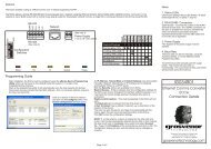
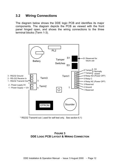
3.2 Wiring Connections<br />
The diagram below shows the <strong>DDE</strong> logic PCB and identifies its major<br />
components. The diagram depicts the PCB as viewed with the front<br />
panel hinged open, and shows the wiring connections to the three<br />
terminal blocks (Term 1-3).<br />
PL2<br />
Battery<br />
Tamper<br />
Switches<br />
S1<br />
S3<br />
S1 Reserved for<br />
future use<br />
3 - RS232 Ground<br />
2 - RS-232 Receive In<br />
1 - RS232 Transmit Out*<br />
2 - Power supply 0V<br />
1 - Power Supply + 12V<br />
Term3<br />
1<br />
Term2<br />
1<br />
Term1<br />
1<br />
S3<br />
8 Tamper<br />
Normally<br />
7 Tamper closed<br />
6 Relay NO (Power OFF)<br />
5 Relay C<br />
4 Relay NC (Power OFF)<br />
3 Reserved<br />
2 Ground<br />
1 Reserved<br />
EPROM<br />
Sounder<br />
* RS232 Transmit out ( used for self-test only. See section 6.1)<br />
FIGURE 3<br />
<strong>DDE</strong> LOGIC PCB LAYOUT & WIRING CONNECTION<br />
<strong>DDE</strong> Installation & Operation Manual - Issue: 5 August 2000 - Page 12