ParSec Data Display & Entry Panel (DDE ... - How do I
ParSec Data Display & Entry Panel (DDE ... - How do I
ParSec Data Display & Entry Panel (DDE ... - How do I

Create successful ePaper yourself
Turn your PDF publications into a flip-book with our unique Google optimized e-Paper software.
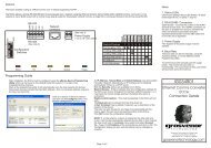
Design<br />
The <strong>DDE</strong> consists of a hinged all metal housing which provides<br />
protection and security to the internal Logic Printed Circuit Board (PCB).<br />
The front panel comprises a 2-line x 20 character back-lit LCD panel, on<br />
which alarms and status information are displayed, and a numeric<br />
membrane keypad for system configuration and tag control. The front<br />
panel also includes two LED's that indicate power on (green) and an<br />
alarm (red).<br />
The <strong>DDE</strong> front cover is normally supplied with standard M3 x 10mm<br />
long cross head screws, which may be replaced by security or “Torx”<br />
head screws. Newmark provide these alternative security screws with<br />
every unit. To use these alternative fixings you will require the following<br />
tools; “Torx” type TX10 screwdriver or a Newmark security driver (Part<br />
no SS0001).<br />
Any attempt to remove the front cover will operate the internal antitamper<br />
switch that may be used to trigger a local or remote alarm.<br />
The housing rear panel provides wall mounting points, cable entry holes<br />
and a chassis earth/ground point.<br />
The <strong>DDE</strong> logic PCB is mounted on the rear of the hinge-<strong>do</strong>wn front<br />
panel and permits easy access to the connection terminals and<br />
components for installation and maintenance.<br />
<strong>DDE</strong> Installation & Operation Manual - Issue: 5 August 2000 - Page 7