Enclosure for SATEON Access Control Equipment ... - Grostech.com
Enclosure for SATEON Access Control Equipment ... - Grostech.com
Enclosure for SATEON Access Control Equipment ... - Grostech.com

You also want an ePaper? Increase the reach of your titles
YUMPU automatically turns print PDFs into web optimized ePapers that Google loves.
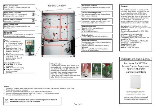
Board Ground Point<br />
EZ-IDC1 / IOC1 chassis connection via<br />
mounting screw<br />
Board Power Connector<br />
EZ-IDC1 / IOC1 12V power supply<br />
including mains present signal<br />
Tamper Switch Connector<br />
Connect to EZ-IDC/IOC<br />
Board Ground Point<br />
EZ-IDC2 / IOC2 chassis connection via<br />
mounting screw<br />
Mounting Position<br />
EZ-IDC/IOC<br />
Two EZ-IDC/IOC boards may be mounted in<br />
the enclosure in these positions<br />
Fuses<br />
l Lock output fuse (FH1)<br />
3.15A quick blow, protects<br />
against overload on lock<br />
output<br />
l Battery Overload Fuse<br />
(FH2) 5A quick blow, limits<br />
maximum discharge<br />
current<br />
l Battery Charge Fuse (FH3)<br />
500mA quick blow,<br />
protects charge circuit if<br />
battery faulty<br />
EZ-ENC-2A-230V<br />
Box Tamper Switches<br />
Two switches located top and bottom wired<br />
in series<br />
<strong>Enclosure</strong> Mounting Points<br />
Use suitable screws through dimpled holes<br />
(3) to secure enclosure<br />
Mounting Position Ancillary Boards<br />
Two ancillary boards such as LH-ENET-485<br />
may be mounted in these positions<br />
Battery Connections<br />
Connect to 7AH lead-acid battery<br />
RED cable positive +<br />
BLACK cable negative -<br />
Battery Position<br />
Locate battery with terminals on the left<br />
Mains IN Connections<br />
Wire in<strong>com</strong>ing mains cable to terminal block-<br />
L Live 110-230Vac<br />
E Earth (terminal is connected to chassis)<br />
N Neutral<br />
Observe applicable electrical regulations.<br />
This unit must be earthed.<br />
General<br />
The EZ-ENC-xxxxxxx is an enclosure with<br />
integrated power supply and battery backup<br />
<strong>for</strong> housing and powering <strong>SATEON</strong> and<br />
JANUS equipment. The PSU provides a<br />
separately fused and switched output <strong>for</strong> lock<br />
supply which can be switched off when the<br />
IDC shuts down. The enclosure will<br />
ac<strong>com</strong>modate two EZ IDC or IOC plus two<br />
ancillary boards such as EZ-LH-ENET-485.<br />
Mains Input - 110-230Vac 0.7A 50-60Hz<br />
DC Output - 3A total (EZ-IDC power plus lock<br />
power output)<br />
Operating Temperature 0 to +50°C (32 to<br />
122°F)<br />
Humidity 5-90% non condensing<br />
Environmental Protection IP50<br />
Cable Entry - Knock-outs on four sides and<br />
back 20mm (3/4")<br />
Dimensions - Width 280mm (11") Height<br />
385mm (15.2") Depth 80mm (3")<br />
Weight 2.8kg (6lb 2oz)<br />
Finish - White painted<br />
Material - Steel, zinc coated<br />
IG056R01-EZ-ENC-2A-230V<br />
Lock Output Terminals<br />
l LCK PWR +12V output<br />
lock supply<br />
l GND 0V out <strong>for</strong> lock supply<br />
l LCK EN <strong>Control</strong> input to<br />
enable lock supply<br />
(5V=ON)<br />
Fitting Boards<br />
1. Identify hole positions in the enclosure <strong>for</strong><br />
the board and fit the plastic mounting pillars<br />
(supplied with the board) to the enclosure.<br />
Note that the short spigot end must be<br />
inserted in the enclosure hole as shown.<br />
Press into the hole until they click<br />
2. Now fit the board onto the mounting pillars<br />
3. For IDC/IOC fit mounting screw<br />
1 2 3<br />
<strong>Enclosure</strong> <strong>for</strong> <strong>SATEON</strong><br />
<strong>Access</strong> <strong>Control</strong> <strong>Equipment</strong><br />
EZ-ENC-2A-230V<br />
Installation Details<br />
Notes<br />
1. Hazardous voltages are accessible within the enclosure, disconnect mains supply be<strong>for</strong>e removing cover.<br />
2. The enclosure must be grounded.<br />
3. Electrical regulations and labelling must be adhered to with installation.<br />
4. Refer to sub-assembly installation guide e.g. EZ-IDC or EZ-IOC <strong>for</strong> wiring details.<br />
5. Product is intended <strong>for</strong> indoor use only.<br />
WEEE: Please refer to www.grosvenortechnology.<strong>com</strong> <strong>for</strong> disposal<br />
instructions under EU Directive 2002/96/EC<br />
Page 1 of 2<br />
Grosvenor Technology Ltd, Millars Three,<br />
Southmill Road, Bishop’s Stort<strong>for</strong>d,<br />
Hert<strong>for</strong>dshire, UK. Tel: +44 (0)1279 838000<br />
www.grosvenortechnology.co.uk<br />
www.grosvenortechnology.<strong>com</strong>
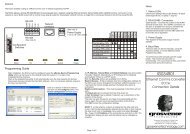
Installation<br />
Fix the enclosure to a flat surface using the three dimpled holes with suitable screws. The<br />
dimples provide a spacing from the wall which is necessary to ac<strong>com</strong>modate items protruding on<br />
the back such as screw heads and PCB mounting pillars. The spacing provided by the dimples<br />
will help in preventing distortion of the enclosure when fixing to slightly uneven surface however<br />
care should be taken to avoid distorting the enclosure if the surface is too uneven.<br />
Mechanical<br />
Drawing Dimensions - Shown in mm<br />
Cable Entry - Knock-outs on four sides and<br />
back 20mm.<br />
The enclosure is intended <strong>for</strong> indoor use only and should be located in a dry non-corrosive<br />
environment.<br />
Mount the enclosure in either of the orientations shown.<br />
UP<br />
Block Diagram<br />
The diagram below shows how different elements of the power supply are interconnected. The<br />
lock power switch provides a shut-down <strong>for</strong> the lock power supply when the EZ board shutsdown<br />
(refer to EZ board Installation Guide <strong>for</strong> wiring details).<br />
The EZ-ENC-2A-230V is capable of powering two EZ boards, battery charging and providing a<br />
minimum of 2Amps <strong>for</strong> locks and readers.<br />
Mains IN<br />
110-230Vac<br />
Mains PSU<br />
12Vdc<br />
Boost<br />
3Amps<br />
Mains Present Signal<br />
13.6Vdc<br />
To EZ-Board<br />
FH3<br />
FH2<br />
Lock<br />
Power<br />
Switch<br />
FH1<br />
Lock Power<br />
Lock Power<br />
Enable Signal<br />
(from EZ Board)<br />
Battery<br />
Page 2 of 2