VRED - Virtual Reality Editor - PI-VR GmbH
VRED - Virtual Reality Editor - PI-VR GmbH
VRED - Virtual Reality Editor - PI-VR GmbH

Create successful ePaper yourself
Turn your PDF publications into a flip-book with our unique Google optimized e-Paper software.
3.19. TRACKING 3. USER INTERFACE<br />
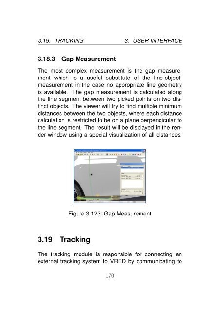
3.18.3 Gap Measurement<br />
The most complex measurement is the gap measurement<br />
which is a useful substitute of the line-objectmeasurement<br />
in the case no appropriate line geometry<br />
is available. The gap measurement is calculated along<br />
the line segment between two picked points on two distinct<br />
objects. The viewer will try to find multiple minimum<br />
distances between the two objects, where each distance<br />
calculation is restricted to be on a plane perpendicular to<br />
the line segment. The result will be displayed in the render<br />
window using a special visualization of all distances.<br />
Figure 3.123: Gap Measurement<br />
3.19 Tracking<br />
The tracking module is responsible for connecting an<br />
external tracking system to <strong><strong>VR</strong>ED</strong> by communicating to<br />
170
3.19. TRACKING 3. USER INTERFACE<br />
one or more <strong>VR</strong>PN (<strong>Virtual</strong> <strong>Reality</strong> Peripheral Network)<br />
servers. <strong>VR</strong>PN is an open source standard library for accessing<br />
many different tracking systems with a unified approach.<br />
Each <strong>VR</strong>PN tracking server can contain any number<br />
of sensors, which in turn are classified as follows: Buttons,<br />
Analogs, Dials and Bodies. Each server is configured<br />
by a <strong>VR</strong>PN configuration file, which must be edited<br />
by hand.<br />
3.19.1 Tracking Modes<br />
The tracking system supports the following four different<br />
modes, which can be selected independent for each<br />
tracked body.<br />
• Powerwall Mode. The powerwall mode is used for<br />
headtracking a spectator in front of a powerwall. In<br />
order for this mode to work correctly you either have<br />
to enable the Powerwall Mode in the Stereo menu<br />
in the main menu bar or you have to use a cluster for<br />
viewing. The powerwall tracking mode is enabled by<br />
setting the bodies target name to powerwall in the<br />
tracking module.<br />
• HMD Mode. The HMD mode is intended for headtracking<br />
a head mounted display. The HMD tracking<br />
mode is enabled by setting the bodies target name<br />
to powerwall in the tracking module. You do not<br />
171
3.19. TRACKING 3. USER INTERFACE<br />
need to change anything in contrast to the Powerwall<br />
Mode as described above.<br />
• Relative Object Mode. For tracking objects other<br />
than the spectator there is the Relative Object<br />
Mode. This mode tracks a physical body and moves<br />
a node in the virtual scene relativ to the camera position.<br />
That means if you navigate through the virtual<br />
scene, the tracked virtual object remains at the<br />
same location relative to the camera (and seems<br />
to move through the scene as you navigate). This<br />
mode is useful for items that the spectator can carry<br />
around (a flashlight or simply his hands).<br />
• Absolute Object Mode. As opposed to the relative<br />
object mode the Absolute Object Mode tracks<br />
a physical body and moves a node in the virtual<br />
scene in absolute mode. That means that when you<br />
navigate away from the virtual representation of the<br />
tracked physical body, this representation departs<br />
from the viewer in the virtual world. This mode is<br />
useful if the virtual scene has a static physical representation<br />
in reality and you need to track objects<br />
relative to this representation. For example you put<br />
a tracked item onto a table that coexists in the virtual<br />
scene and in the real world.<br />
172
3.19. TRACKING 3. USER INTERFACE<br />
3.19.2 Coordinate Systems<br />
The main difficulty with tracking lays within the three different<br />
coordinate systems that have to be considered:<br />
• Scene coordinate system. This is the coordinate<br />
system of your virtual world, that is the scene loaded<br />
into <strong><strong>VR</strong>ED</strong>. Note that all virtual representation of<br />
bodies must be transform nodes. These use a local<br />
coordinate system that is determined by the product<br />
of all transform nodes above itself.<br />
• Tracking coordinate system. The tracking coordinate<br />
system belongs to the tracking hardware. This<br />
coordinate system may be the same as the physical<br />
coordinate system of your application, but it may<br />
also be completely different, concerning both the<br />
origin and the orientation.<br />
• Physical coordinate system. The physical coordinate<br />
system is that of the real world and is normally<br />
defined by your needs (e.g. where the origin is and<br />
the orientation).<br />
The difficult task is to get these three coordinate systems<br />
working together. Fortunately <strong><strong>VR</strong>ED</strong> has some built-in<br />
capabilities to calibrate the coordinate systems to easily<br />
change the origin or orientation. But still, you - as the<br />
user - have to be aware of what you are doing and how<br />
the coordinate systems should be mapped on each other.<br />
173
3.19. TRACKING 3. USER INTERFACE<br />
Figure 3.124: An example of a tracking setup, where both<br />
the tracking coordinate system and the bodies coincide<br />
with their virtual representations.<br />
Hint<br />
Of course it is the easiest, when all three coordinate systems<br />
are the same – but in most cases this is not possible.<br />
But a careful design of the scene and the setup in the<br />
physical world can guarantee that these two coordinate<br />
systems are the same. Plus it is much easier if the orientation<br />
of the tracking coordinate system and of the virtual<br />
scene is the same. This might require a recalibration of<br />
the tracking system with the original tracking software.<br />
3.19.3 Calibration<br />
In order to help the user at bringing together the three different<br />
coordinate systems, <strong><strong>VR</strong>ED</strong> offers the ability to cali-<br />
174
3.19. TRACKING 3. USER INTERFACE<br />
brate a complete tracking space and individual sensors.<br />
Calibrating a Sensor<br />
Calibrating a sensor effectively does the following thing:<br />
The tracking system resets the orientation of the sensor<br />
and moves its origin to its current location. This sort of<br />
calibration is useful for initially resetting the position of a<br />
sensor.<br />
In <strong><strong>VR</strong>ED</strong> calibrating a body simply resets its virtual<br />
representation to the origin of its local coordinate system.<br />
Figure 3.125: A body that needs calibration, because its<br />
virtual position and orientation differ from its real position<br />
175
3.19. TRACKING 3. USER INTERFACE<br />
Figure 3.126: After calibrating a body, it will be reset, such<br />
that its virtual position and orientation coincide with its virtual<br />
local coordinate system.<br />
Calibrating a Coordinate System<br />
The calibration of a tracking space is a bit more complicated.<br />
In order to calibrate the space you need to specify<br />
one sensor within this space. Then the calibration will<br />
move and rotate the space in such a manner that the origin<br />
and orientation of the complete tracking space coincides<br />
with the origin and orientation of the chosen sensor.<br />
This is especially useful to change the orientation of the<br />
tracking space in order to meet the needs of the given<br />
virtual and real scene.<br />
In <strong><strong>VR</strong>ED</strong> the tracking space is calibrated with the help<br />
of a body. You can use any body of the tracking system<br />
and use its implicit coordinate system as a reference for<br />
the tracking coordinate system. After calibrating the coor-<br />
176
3.19. TRACKING 3. USER INTERFACE<br />
dinate system, that body will be at the origin of the calibrated<br />
tracking space.<br />
Figure 3.127: The tracking coordinate system and the virtual<br />
coordinate system do not overlap.<br />
Figure 3.128: Calibration of the tracking coordinate system<br />
by using a body as a reference coordinate system.<br />
177
3.19. TRACKING 3. USER INTERFACE<br />
3.19.4 Tracking Devices<br />
The first and most important tab of the tracking module<br />
within <strong><strong>VR</strong>ED</strong> is dedicated to the tracking devices and their<br />
sensors. Each tracking device represents a complete<br />
tracking system consisting of a tracking space, a coordinate<br />
system and one or more sensors.<br />
Figure 3.129: List of all Tracking Devices<br />
You can add a new tracking system by using the context<br />
menu in the device list. You have to enter its name (in<br />
the form trackername@computername) and then a connection<br />
to that <strong>VR</strong>PN server will be established. Then you<br />
can start or stop the complete tracking process by clicking<br />
on the checkbox Enable Tracking left of the device list.<br />
By using the last two columns in the device list you can<br />
rotate the coordinate system (Z-Up) and enable or disable<br />
the complete device (On).<br />
You can also calibrate the coordinate system as de-<br />
178
3.19. TRACKING 3. USER INTERFACE<br />
scribed above. A calibration needs one sensor that describes<br />
the new coordinate systems, both its new origin<br />
and its new orientation. You can also edit the calibration<br />
matrix directly, but it is discouraged to use this method.<br />
When a device is created and selected, sensors can<br />
be added to the device. Unfortunetaly <strong>VR</strong>PN does not<br />
tell which sensors are connected, so you have to enter<br />
them manually in the sensor list. You can also name each<br />
sensor for accessing these via Python-scripts – the name<br />
has no other function. The following sensor types are supported:<br />
• Buttons.<br />
• Analogs.<br />
• Dials.<br />
• Bodies.<br />
Bodies probably are the most interesting sensor, as these<br />
are the only sensors that have a position and orientation<br />
in space. Thus these are also the only sensors that can<br />
be calibrated or connected to a node.<br />
Connecting a body to a node is an important task that<br />
will update a transform nodes matrix with the values coming<br />
from the corresponding sensor. In order to connect a<br />
sensor with a node (only transform nodes are supported),<br />
simply enter the name of the node in the field Target of<br />
the sensor. There are three special targets that connect<br />
a sensor to the camera instead of a node. These are as<br />
follows:<br />
179
3.19. TRACKING 3. USER INTERFACE<br />
• powerwall. This special target enables headtracking<br />
as needed for powerwall projections. In order to<br />
make this mode work, you either have to use a render<br />
cluster or enable the powerwall viewing mode<br />
from the main menu bar in <strong><strong>VR</strong>ED</strong>.<br />
• hmd. The HMD mode is for head mounted displays.<br />
• camera. The camera mode is a very special mode<br />
that simply tracks the position of a sensor but does<br />
not track its orientation.<br />
In addition to these special targets you can also enable or<br />
disable the absolute tracking mode as described above<br />
by clicking the checkbox in the last column of the sensor<br />
list. Unchecking the absolute tracking mode will enable<br />
a tracking mode that transforms the target relativ to the<br />
camera position.<br />
Using the context menu you can also calibrate any<br />
sensor of type body, as described above. The calibration<br />
will reset the position and orientation of the node that<br />
is connected to the body.<br />
3.19.5 Tracking Servers<br />
The second tab of the tracking module contains a list of<br />
<strong>VR</strong>PN servers which are controlled by the cluster service.<br />
You can add new servers by using the context menu and<br />
entering their network adress. All servers in this list can<br />
be started and stopped using the context menu. Note<br />
180
3.19. TRACKING 3. USER INTERFACE<br />
Figure 3.130: List of all Tracking Servers<br />
that the cluster service must be running on the remote<br />
machine to be useable with this list.<br />
3.19.6 Connecting the Camera to a Node<br />
One important tracking scenario is attaching the camera<br />
to a tracked node. This is especially useful for driving simulators,<br />
where a spectator sits within a car that is driving<br />
through the scene, but the camera should move with the<br />
car instead of remaining at a fixed point.<br />
Such effects can be achieved by attaching the camera<br />
to any node in the scene graph. To connect the camera<br />
to a nodem, first select the corresponding node and then<br />
press on the button Connect to Beacon within the camera<br />
module. This establishes a connection. To activate<br />
the connection, you need to check Enable Camera Bea-<br />
181
3.19. TRACKING 3. USER INTERFACE<br />
Figure 3.131: Attaching the Camera to a Node<br />
con. This will set the camera to the nodes location. As<br />
long as Enable Mouse Navigation still is checked, you<br />
can use your mouse for navigation (relative to the node).<br />
182