Replacement of Chamber Heater Elements - Sigma Systems ...
Replacement of Chamber Heater Elements - Sigma Systems ...
Replacement of Chamber Heater Elements - Sigma Systems ...

You also want an ePaper? Increase the reach of your titles
YUMPU automatically turns print PDFs into web optimized ePapers that Google loves.
inTEST Thermal Solutions<br />
ISO 9001 Registered<br />
Tel: +1.781.688.2300 41 Hampden Road, Mansfield, MA 02048 USA www.inTESTthermal.com<br />
<strong>Replacement</strong> <strong>of</strong> <strong>Chamber</strong> <strong>Heater</strong> <strong>Elements</strong><br />
_____________________________________________________________________________________________<br />
Note: this Service Bulletin replaces SB2200.00<br />
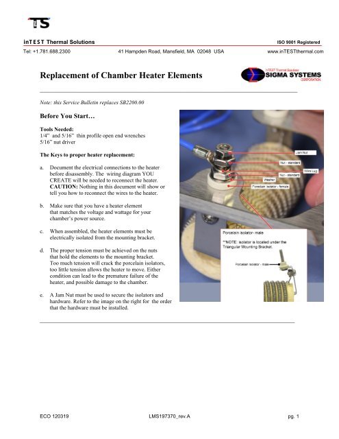
Before You Start…<br />
Tools Needed:<br />
1/4” and 5/16” thin pr<strong>of</strong>ile open end wrenches<br />
5/16” nut driver<br />
The Keys to proper heater replacement:<br />
a. Document the electrical connections to the heater<br />
before disassembly. The wiring diagram YOU<br />
CREATE will be needed to reconnect the heater.<br />
CAUTION: Nothing in this document will show or<br />
tell you how to reconnect the wires to the heater.<br />
b. Make sure that you have a heater element<br />
that matches the voltage and wattage for your<br />
chamber’s power source.<br />
c. When assembled, the heater elements must be<br />
electrically isolated from the mounting bracket.<br />
d. The proper tension must be achieved on the nuts<br />
that hold the elements to the mounting bracket.<br />
Too much tension will crack the porcelain isolators,<br />
too little tension allows the heater to move. Either<br />
condition can lead to the premature failure <strong>of</strong> the<br />
heater, and possible damage to the chamber.<br />
e. A Jam Nut must be used to secure the isolators and<br />
hardware. Refer to the image on the right for the order<br />
that the hardware must be installed.<br />
____________________________________________________________________________________________<br />
ECO 120319 LMS197370_rev.A pg. 1
inTEST Thermal Solutions<br />
ISO 9001 Registered<br />
Tel: +1.781.688.2300 41 Hampden Road, Mansfield, MA 02048 USA www.inTESTthermal.com<br />
1. Place the male porcelain inserts onto the heater mounting screws. The small portion <strong>of</strong> the<br />
porcelain insert points away from the body <strong>of</strong> the heater element.<br />
Figure: 1<br />
Porcelain isolator(s) - Male<br />
2. Place the heater element on a flat surface with the mounting screws facing up. Put the Triangular<br />
mounting bracket on the heater and guide the screws and Porcelain Isolators (male) inserts through<br />
the holes in the mounting bracket. Repeat with additional elements, if any.<br />
Note: The bracket flange must point away from the heater element.<br />
Figure: 2<br />
Triangular Mounting Bracket<br />
ECO 120319 LMS197370_rev.A pg. 2
inTEST Thermal Solutions<br />
ISO 9001 Registered<br />
Tel: +1.781.688.2300 41 Hampden Road, Mansfield, MA 02048 USA www.inTESTthermal.com<br />
3. Place the female porcelain isolators over the screws and mate them to the male porcelain isolators<br />
protruding through from the opposite side.<br />
Figure: 3<br />
Porcelain Isolators - Female<br />
4. Place a Washer and a Standard Nut on each mounting screws.<br />
Figure: 4<br />
Washer and Standard Nut<br />
ECO 120319 LMS197370_rev.A pg. 3
inTEST Thermal Solutions<br />
ISO 9001 Registered<br />
Tel: +1.781.688.2300 41 Hampden Road, Mansfield, MA 02048 USA www.inTESTthermal.com<br />
5. Using a nut driver, tighten the standard nuts until they are just snug.<br />
NOTE This is a critical part <strong>of</strong> the assembly!<br />
Over tightening can crack the porcelain isolators and allow the heater to short and fail.<br />
Under tightening can leave too much play on the elements so they will rattle in the wind <strong>of</strong> the<br />
blower and can short on each other or the mounting bracket, and/or damage the porcelain isolators.<br />
Figure: 5<br />
Nut Driver to Tighten Standard Nut<br />
6. Once snug, use a felt pen to draw a line down the center <strong>of</strong> one <strong>of</strong> the nut flats and continue the<br />
line onto the female porcelain isolator.<br />
Figure: 6<br />
Mark Standard Nut and Porcelain Isolator (Female)<br />
ECO 120319 LMS197370_rev.A pg. 4
inTEST Thermal Solutions<br />
ISO 9001 Registered<br />
Tel: +1.781.688.2300 41 Hampden Road, Mansfield, MA 02048 USA www.inTESTthermal.com<br />
7. Back <strong>of</strong>f (loosen) the standard nut 1/12 <strong>of</strong> a turn (1/2 flat), so that the nearest point <strong>of</strong> the nut lines<br />
up with the line on the porcelain isolator.<br />
This provides enough clearance to allow for the expansion and contraction that occurs as the parts<br />
undergo sever temperature changes in the chamber.<br />
Figure: 7<br />
Loosen Standard Nut – use Markings as a guide<br />
8. Attach the Wire Lug.<br />
Figure: 8<br />
Wire Lug<br />
ECO 120319 LMS197370_rev.A pg. 5
inTEST Thermal Solutions<br />
ISO 9001 Registered<br />
Tel: +1.781.688.2300 41 Hampden Road, Mansfield, MA 02048 USA www.inTESTthermal.com<br />
9. Use a Nut Driver to tighten a Standard Nut on top <strong>of</strong> the Wire Lug.<br />
Figure: 9<br />
Standard Nut on Wire Lug<br />
10. Install a Jam Nut on top <strong>of</strong> the Standard Nut. Use two wrenches:<br />
1 wrench to hold the Standard Nut<br />
1 wrench to tighten the Jam Nut<br />
Figure: 10<br />
Jam Nut<br />
ECO 120319 LMS197370_rev.A pg. 6
inTEST Thermal Solutions<br />
ISO 9001 Registered<br />
Tel: +1.781.688.2300 41 Hampden Road, Mansfield, MA 02048 USA www.inTESTthermal.com<br />
Appendix A:<strong>Heater</strong>s With Fiber Washers<br />
If you have a heater assembly that has fiber washers (shown in the images below), discard those washers.<br />
The Hardware and Procedure in this Service Bulletin negate the need for fiber washers.<br />
a. Diagram where all wires and bus bars are connected to the heater<br />
b. Disassemble your old unit and remove the fiber washers. (These washers were originally added to compensate<br />
for expansion and contraction).<br />
ECO 120319 LMS197370_rev.A pg. 7
inTEST Thermal Solutions<br />
ISO 9001 Registered<br />
Tel: +1.781.688.2300 41 Hampden Road, Mansfield, MA 02048 USA www.inTESTthermal.com<br />
c. To install a new heater, follow the Numbered Steps on the previous pages <strong>of</strong> this Service Bulletin. The number<br />
<strong>of</strong> heaters vary from system to system, but once you are finished, your installed heater(s) should look similar to<br />
this:<br />
ECO 120319 LMS197370_rev.A pg. 8
inTEST Thermal Solutions<br />
ISO 9001 Registered<br />
Tel: +1.781.688.2300 41 Hampden Road, Mansfield, MA 02048 USA www.inTESTthermal.com<br />
d. Reattach the bus bars and wiring to restore the heater wiring to its original condition.<br />
NOTE: You should use the wiring diagram you created before disassembling your heater.<br />
No Matter what your heater configuration is, document the bus and wiring before disassembly.<br />
Then follow the Numbered Steps in this Service Bulletin to install replacement elements.<br />
inTEST Thermal Solutions engineers highly customizable Thermal <strong>Chamber</strong>s, as a result, there are many<br />
different configurations for <strong>Heater</strong>s. The image below shows one configuration with multiple heaters installed.<br />
This configuration does not use the Triangle Bracket, the <strong>Heater</strong>s are mounted on a Rectangular Bracket- - but the<br />
hardware used to mount the heaters is the same and a wiring diagram is needed to re-wire the heaters.<br />
ECO 120319 LMS197370_rev.A pg. 9