Service Bulletin #SB2002.00 Calibration of CC3, CC3.5, and C4 ...
Service Bulletin #SB2002.00 Calibration of CC3, CC3.5, and C4 ...
Service Bulletin #SB2002.00 Calibration of CC3, CC3.5, and C4 ...
- No tags were found...

You also want an ePaper? Increase the reach of your titles
YUMPU automatically turns print PDFs into web optimized ePapers that Google loves.
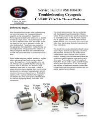
1817 John TowersEl Cajon, CA 92020619.258.3700<strong>Service</strong> <strong>Bulletin</strong> <strong>#SB2002.00</strong><strong>Calibration</strong> <strong>of</strong> <strong>CC3</strong>, <strong>CC3</strong>. 5 , <strong>and</strong><strong>C4</strong> ControllersBefore you Start...This bulletin covers the calibration <strong>of</strong> Sigma <strong>CC3</strong>,<strong>CC3</strong>. 5 , <strong>and</strong> <strong>C4</strong> controllers to give accurate temperaturereadings when used with precision 500Ω PlatinumRTDs (Resistance Temperature Device). Thisprocedure will calibrate the controller ± 0.1°C for thest<strong>and</strong>ard operation range <strong>of</strong> –100°C to +199°C. Ifyou are using the Sigma Controller Test Box we alsodescribe how to check other important functions <strong>of</strong>the controller.Sigma controllers seldom require calibration, usuallyevery 24 months is sufficient. However, if your testsrequire extreme accuracy it would be wise to checkcalibration more frequently.Sigma controllers determine temperature by measuringthe resistance across the probes. (Sigmacontrollers work only with precision 500Ω PlatinumRTDs (Resistance Temperature Device)). Therefore,the accuracy <strong>of</strong> your calibration is dependanton the accuracy <strong>of</strong> the equipment you use to provideresistance. If the equipment you have available isnot highly accurate, we recommend that you contacta lab service company or Sigma about calibration.Tools Needed:Anti-Static workstation/mat/trayPersonal Anti-Static DeviceTrim pot adjustment tool#2 Phillips Screw DriverVoltmeter (± 2% accuracy @ 15°– 35°C)Decade Resistance Box(0-1k ohm within 0.1%accuracy @15° – 35°C)- - Recommended - -Sigma Controller Test Box(Available from Sigma - see Appendix A)(For this procedure we use an I.E.T. HARS-X-4-.1 ResistanceSubstituter as the decade resistance box, <strong>and</strong> theFluke 87 Digital multimeter (DMM) for the voltmeter.)This <strong>Service</strong> <strong>Bulletin</strong> is broken into three sections.Section A covers Common Setup procedures.Section B covers calibration using the Sigma ControllerTest Box (see Appendix A ). This test box simplifiescalibration <strong>and</strong> provides <strong>and</strong> operational test<strong>of</strong> the blower, cooling, <strong>and</strong> heating Triacs, as well asoperation <strong>of</strong> the Fail-Safe.Section C covers how to calibrate the controllerwithout the Sigma Controller Test Box. It does NOTcheck operation <strong>of</strong> the blower, cooling, <strong>and</strong> heatingTriacs or operation <strong>of</strong> the Fail-Safe circuit.Sigma Controller Test Box in use with a <strong>C4</strong>controller <strong>and</strong> decade resistance substituter.WARNING: This calibration procedure requiresthis equipment to be open <strong>and</strong> energized. Notobserving safe practices while calibrating thecontroller can result in damage to the equipment<strong>and</strong>/or personal injury.CAUTION: If you do not have the proper tools<strong>and</strong> Anti-Static mats <strong>and</strong> straps DO NOT attemptthis procedure as there is a high probability <strong>of</strong>damaging the controller. Call Sigma <strong>and</strong> requesta RMA <strong>and</strong> we can perform the calibration for youas a service item, or contact a service technicianin your local area to perform the calibration.SB2002.00-1
A. Common Test SetupWarning: Once removed from their cabinets, Sigmacontrollers are very static sensitive, so it is importantthat you only h<strong>and</strong>le the controller while attachedto a personal ESD device. It is also highly recommendedthat before working on the unit that youprovide a direct ground for the controller.If you are using the Sigma Controller Test box simplyplug the green lead wire that comes with the test boxinto the green grounding plug on the side <strong>of</strong> the testbox.If you are not using the Sigma Controller Test Box,then run a wire from lug 3 on the back <strong>of</strong> the controllerto a good known ground source.If you cannot provide an ESD environment <strong>and</strong> thegrounding described above, DO NOT proceed as itis highly likely that you will damage the controller,necessitating extensive <strong>and</strong> expensive repairsA1. Set the controller probe correction parameter fieldsto their default (no correction) values. If you have a<strong>CC3</strong> controller, skip to A1b.A1a. With the temperature scale (setup parameterF16=0) set to °C, setup parameters F17, F18, F21,& F22 should be set to 0 <strong>and</strong> setup parameters F19,F20, F23, & F24 should be set to 100 (image 1-1)A1b. Set F1 = 2. (sets controller to 2 probe mode)(See the controller manual for instructions on settingthe parameter fields, if you need additional help).Image 1-1Caution: If the s<strong>of</strong>tware probe corrections are notset to their defaults, calibration may not be possibledue to range limitations <strong>of</strong> the calibration potentiometers.In addition, the temperatures reported bythe probe(s) will be incorrect. Incorrect calibrationcan result in extreme <strong>and</strong>/or unexpected temperaturesthat will likely result in damage to equipment<strong>and</strong> test specimens, <strong>and</strong> harm to personnel.A2. Remove power from the controller.Caution: Failure to remove power from the unit caneasily result in damage to the controller <strong>and</strong>/or possiblepersonal injury. The safest <strong>and</strong> surest way todo this is to unplug or disconnect the power source.Note: Even with the controller switch in the OFFposition, power is still flowing to the controller.SB2002.00-2
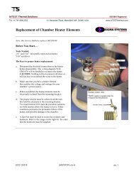
A3. Remove the 4 outside corner screws on the front<strong>of</strong> the controller. (image 1-2)Note: If you do not have a Sigma controller testbox, <strong>and</strong> you do have a PFS-1 or PFS-2 Fail-Safeyou may need to loosen the screws on the PFS<strong>and</strong> pull it out at the same time, so the two canremain connected, as this will be required foroperation.A4. Remove the controller <strong>and</strong> place it on a low ESDsurface.Recommended h<strong>and</strong>ling <strong>of</strong> the controller is by themetal face plate or metal top cage <strong>of</strong> the controllerwhile wearing a grounding device.A5. Test the controller for good continuity.Attach the common lead from your DMM to lug 3on the back <strong>of</strong> the controller, set your DMM to Ω<strong>and</strong> use the positive lead on one <strong>of</strong> the four baremetal screws that hold the numeric pad in place.An acceptable level is 2Ω or less. (image 1-3)If the continuity is greater that 2Ω contact Sigmasystems for advisement on repair.Anti-Staticwrist b<strong>and</strong>Anti-Static matImage 1-3 Image 1-2SB2002.00-3
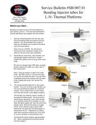
B10. If your controller has a fiber anti-static board (Image1-6a) you will want to remove at least one <strong>of</strong> the backscrews so that you have access to test points TP1 <strong>and</strong>TP6 [TP2 on older controllers] (image 1-6a or 6c).TP1TP2Fiber Anti-static board<strong>CC3</strong> controller - test points TP1 <strong>and</strong> TP2. Thepoints are labeled on the reverse side <strong>of</strong> the board.Image 1-6aTP1TP6Image 1-6b<strong>CC3</strong>.5 & <strong>C4</strong> test points TP1 & TP6Image 1-6c<strong>Calibration</strong>WARNING: This calibration procedure requiresthis equipment to be open <strong>and</strong> energized. Notobserving safe practices while calibrating thecontroller can result in damage to the equipment<strong>and</strong> personal injury.B11. Plug the Sigma Controller Test Box into a 110Voutlet.B12. Turn the controller switch to SETUP <strong>and</strong> verifythat you have set F2, F16, F17, F18, F19, F20,F21, <strong>and</strong> F22 as required on page 1 <strong>of</strong> this bulletin.B13. Set the Decade Resistance Box to 500.0Ω.B14. Turn the controller switch to LOCAL. The firstthing you should see is that light 1 on the SigmaTest Box should come on <strong>and</strong> the controller frontpanel should light (image 1-7). This confirmsthat the blower Triac is switching (good) <strong>and</strong> thatyou are ready to proceed.Image 1-7SB2002.00-5
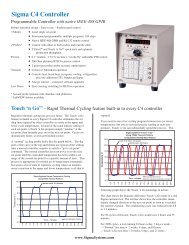
Note: If your controller is reading -5.0° to 5.0°skip steps B15 <strong>and</strong> B16, as these are roughadjustments <strong>and</strong> not needed when the controlleris within ± 5.0°C.Note: Numbers in brackets [##] show locationsnames as marked on <strong>CC3</strong> <strong>and</strong> 3. 5 boards.R5 R2TP1TP6 [TP2]B15. Set your Digital Multi Meter (DMM) to VDC,if your unit does not have an auto-rangecapability, set the range to 20 VDC. Connectthe common lead to lug 3 on the back<strong>of</strong> the controller.Test location TP1 on the side <strong>of</strong> the controller(image 1-8). Adjust the R5 [R29 on<strong>CC3</strong>/3. 5 ] potentiometer slightly until yourDMM reads 7.1 VDC ± 0.0 VDC.B16. Use the DMM to verify that TP6 [TP2] is 1.7VDC ±0.250 mVDC (1.450 – 1.950 VDC).If needed, slightly adjust poteniometer R2[R32].R5R2Image 1-8B17. Set 0.0°C point, by slightly adjust the R2 [R32]potentiometer so that the controller front paneldisplays 0.0°C with no negative sign.B18. Set 100.0°C point, by setting the decade resistancebox to 695.0Ω <strong>and</strong> make sure that the controllerfront panel reads 100.0°C ± 0.1°C (99.9°– 100.1°C). If it doesn’t slightly adjust R2 [R32].B19. Set the decade resistance box back to 500.0Ω<strong>and</strong> verify that the controller reads 0.0°C, withnot negative sign.Image 1-9If the front panel does not read 0.0°C repeatsteps B17-B19.If after a third iteration, the controller still does notconform within the specified tolerances at 500.0Ω<strong>and</strong> 695.0Ω, you will need to contact Sigma torepair the controller.B19. Once calibration is complete you can verify theoperation <strong>of</strong> probe 2 connection by unpluggingthe Black banana plug from the decade resistancebox <strong>and</strong> plugging in the White banana plug.(image 1-11)Image 1-10B20. Set the decade box to 695.0Ω <strong>and</strong> press DISPTEMP on the controller – it should now read:p2 100.0 (100.0°C ± 0.1°C –– 99.9° –100.1°)Note: This will only work only if the controllersetup parameter F1 is set to 2, indicating twoprobes as outline in Section A.SB2002.00-6Image 1-11
At this point you have calibrated the ControllerTo verify other operations <strong>of</strong> the controller proceed.Verifying other functions <strong>of</strong> the controllerwith the Sigma Controller Test Box.The following procedure will test the heating <strong>and</strong> coolingTriacs <strong>and</strong> the Fail-safe circuit <strong>of</strong> the controller. This procedureassumes that you have just finished calibration<strong>of</strong> the controller. If not you must complete the setup asdescribed in Section A <strong>of</strong> this bulletin.PreparationB21. Turn the controller switch to PROGRAM <strong>and</strong> backto LOCAL.Note: If the Green or Red lights illuminate<strong>and</strong> stay On at this point it means that theTriacs have “Latched On” <strong>and</strong> will need to beserviced.B22. Press DISPL CNTL on the controller.Display = s1 nsp (no setpoint)B23. Press CLEAR ENTRY.Display = s (clears entry)B24. Press 1100 ENTERDisplay = s1 100.0 (sets setpoint 1 to 100°C)B25. Press START/STOPThe RUN light on the controller should light.Note: If the Green or Red lights illuminate<strong>and</strong> stay On at this point it means that theTriacs have “Latched On” <strong>and</strong> will need to beserviced.Testing the Cooling TriacsB26. Turn the decade resistance box to 795.0Ω.The controller COOL LED should illuminate <strong>and</strong>the green light (#2) on the test box should comeon .If the green light comes on it verifies the coolingImage 1-12SB2002.00-7
Triacs are functioning. (image 1-12)If the green light does Not come on, repeatthe procedure <strong>and</strong> verify the result, if it fails asecond time contact Sigma for repair.Testing the Heating TriacsB27. Set the decade resistance box to 595.0ΩThe controller HEAT LED should light <strong>and</strong>the red heater lights should come on (lights 3<strong>and</strong> 4). (image 1-13)Note: If the Green light stays On whenyou change to 595.0Ω it means that thecooling Traics have “Latched On” <strong>and</strong>will need to be serviced.If the red lights do come on it verifies that theheating Triacs are functioning.If they do Not come on, repeat the procedure<strong>and</strong> verify the result, if it fails a second timecontact Sigma for repair.Testing the Heater Triacs for “Latch On”B28. Turn the decade resistance box to 795.0ΩThe controller COOL LED should illuminate<strong>and</strong> the green light (#2) on the test boxshould come on.At this point verify that the Red heaterlights have gone Off, if they are still Onit means that the Triacs have “LatchedOn” <strong>and</strong> need to be serviced.Image 1-13Testing Fail-safe CircuitB29. Press <strong>and</strong> hold the red button on the controllertest box for 1 second this should trip thefail-safe circuit in the <strong>C4</strong>.Any heating or cooling lights on the test boxshould go out.Display = fl safeImage 1-14This verifies the fail safe circuitThis completes your calibration <strong>and</strong> testing <strong>of</strong> the controller.If you have only one probe on your system, you will want toSB2002.00-8
eset F1 = 1.This completes the testing <strong>of</strong> the controllerC. Calibrating the Controller without the Sigma ControllerTest BoxPreparationTo use the following procedure you must have completedthe steps outlined in Section A.C1. If it is a chamber controller disconnect the probe wiresfrom lugs 1 & 4 (probe 1) <strong>and</strong> 2 & 4 (probe 2, if attached)(image 1-15).If it is a platform controller proceed to C2 (platform controllershave a 12 pin <strong>and</strong> a 6 pin connector).C2. For a chamber controller make the following connections(image 1-16).Image 1-15ControllerTerminallug 1lug 4lug 3ToDecade BoxDecade BoxGround (if not already attached)For a platform controller make the following connectionon the 6 pin cable connector. (images 1-17a, 17b,17c). Note: Making these connection on the pins atthe end <strong>of</strong> the cable “takes into account” the resistance<strong>of</strong> the cable while calibrating the controller.Lug 1Lug 2Lug 3Lug 4Lug 5Lug 66 PinConnectorToImage 1-16GapPin 4 - GroundPin 6 - Decade boxPin 5 - Decade boxImage 1-17a6 pin connectorseen from pin sidePin 1Pin 3Pin 5Pin 2Pin 4Pin 6GapImage 1-17bImage 1-17cSB2002.00-9
Pin 5Pin 6Pin 4Decade BoxDecade BoxGroundC3. Reconnect the 12 pin cable from the controllerto the 12 pin receptacle from the chamber orplatform.image 1-18TP1TP6Image 1-19aImage 1-19bTP1TP2TP1 <strong>and</strong> TP2 on a <strong>CC3</strong>. The pointsare labeled on the reverse side.Image 1-19c<strong>C4</strong>. If your controller has an anti-static board (Image1-19a) you will want to remove at least one <strong>of</strong> theSB2002.00-10
ack screws, so that you have access to test pointsTP1 <strong>and</strong> TP6 [TP2 on <strong>CC3</strong>/3. 5 ] (image 1-19a, b or c).C5. Reconnect power to the chamber or platform.<strong>Calibration</strong>WARNING: This calibration procedure requires thisequipment to be open <strong>and</strong> energized. Not observingsafe practices while calibrating the controller canresult in damage to the equipment <strong>and</strong> personal injury.CAUTION: NEVER press the controller Start buttonwhile the controller is connected to a fixed resistancedevice, like the decade resistance box used in thisprocedure, while the probes are disconnected fromthe controller, or while the probes are otherwiseremoved from the chamber or platform, as this canlead to a dangerous run away condition, since thecontroller cannot “sense” the chamber/platform temperature,that can result in extreme temperatures <strong>and</strong>cause equipment damage <strong>and</strong>/or personal injury.image 1-20C6. Turn the controller switch to SETUP <strong>and</strong> verify that youhave set F2, F16, F17, F18, F19, F20, F21, <strong>and</strong> F22 asrequired on page 1 <strong>of</strong> this <strong>Bulletin</strong>.C7. Set the Decade Resistance Box to 500.0Ω.C8. Turn the controller switch to LOCAL. The first thing youshould see is the controller LED panel will light <strong>and</strong>after a few seconds it will display the temperature <strong>of</strong>probe one.Sample display = p1 0.1Note: If your controller is reading -5.0 to 5.0°C, skipsteps C9 <strong>and</strong> C10, as these are rough adjustments <strong>and</strong>not needed if your controller is within ± 5°C.image 1-21C9. Set your Digital Multi Meter (DMM) to VDC, if yourDMM does not have auto-range capability, set therange to 20 VDC. Connect the common lead tolug 3 on the back <strong>of</strong> the controller.Test location TP1 on the side <strong>of</strong> the controller(image 1-20). Adjust the R5 [R29 on <strong>CC3</strong>/3. 5 ]potentiometer slightly until the DMM reads 7.1VDC ± 0.0 VDC.C10. Use the DMM to verify that TP6 [TP2] is 1.7 VDC±0.250 mVDC (1.450 – 1.950 VDC) (image 1-21).If needed, slightly adjust poteniometer R2 [R32].C11. Adjust the R2 [R32] potentiometer slightly so that thefront panel displays 0.0°C with no negative sign.Note: This is normally a very fine adjustment.Image 1-22SB2002.00-11
C12. Set the decade resistance box to 695.0Ω <strong>and</strong>check to make sure that the controller front panelreads 100.0°C ± 0.1°C (99.9° – 100.1°C). If itdoesn’t slightly adjust R2 [R32] (image 1-22).C13. Set the decade resistance box back to 500.0Ω <strong>and</strong>verify that the controller reads 0.0°C.If the front panel does not read 0.0°C repeat stepsC11–C13.If after a third iteration, the controller still does notconform within the specified tolerances you willneed to contact Sigma for repair.C14. To verify operation <strong>of</strong> the probe 2 connection,remove the wire connected to lug one <strong>and</strong> connectit to lug 2. (lugs 2 <strong>and</strong> 4 are the Probe 2 connection).C15. Press DISP TEMP on the front <strong>of</strong> the <strong>C4</strong> controllerit should now read the same as the last setting youhad on Probe 1 in step C13.Note: This will only work only if the controller setupparameter F1 is set to 2, indicating that the controllerhas two probes.At this point you have calibrated the ControllerIf you only have one probe you will want to reset F1=1.SB2002.00-12
Appendix AController Test Boxincludes test box <strong>and</strong> 3 cablesSigma item #17008120V-60HzSigma item #17007220-240V-50HzNote item 17007 includes anIEC type inlet connector <strong>and</strong>no power cord. Use any PCtype power cord to connect toyour local power outlet.Controller Test Box#17008 shown above3121 – Cable for Chamber2 – Cable for Platform3 – Cable for Chamber not used in this proceedureSB2002.00-13
NotesDateNameSB2002.00-14