Identifying Valves Used in Sigma Products (SB1001.01)
Identifying Valves Used in Sigma Products (SB1001.01)
Identifying Valves Used in Sigma Products (SB1001.01)

You also want an ePaper? Increase the reach of your titles
YUMPU automatically turns print PDFs into web optimized ePapers that Google loves.
Service Bullet<strong>in</strong> #<strong>SB1001.01</strong><br />
<strong>Identify<strong>in</strong>g</strong> <strong>Sigma</strong> <strong>Valves</strong><br />
1817 John Towers<br />
El Cajon, CA 92020<br />
619.258.3700<br />
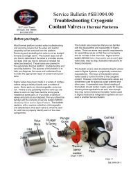
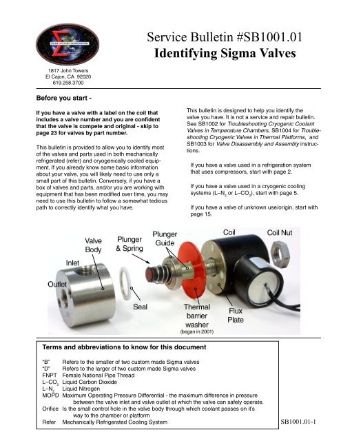
Before you start -<br />
If you have a valve with a label on the coil that<br />
<strong>in</strong>cludes a valve number and you are confident<br />
that the valve is compete and orig<strong>in</strong>al - skip to<br />
page 23 for valves by part number.<br />
This bullet<strong>in</strong> is provided to allow you to identify most<br />
of the valves and parts used <strong>in</strong> both mechanically<br />
refrigerated (refer) and cryogenically cooled equipment.<br />
If you already know some basic <strong>in</strong>formation<br />
about your valve, you will likely need to use only a<br />
small part of this bullet<strong>in</strong>. Conversely, if you have a<br />
box of valves and parts, and/or you are work<strong>in</strong>g with<br />
equipment that has been modified over time, you may<br />
need to use this bullet<strong>in</strong> to follow a somewhat tedious<br />
path to correctly identify what you have.<br />
This bullet<strong>in</strong> is designed to help you identify the<br />
valve you have. It is not a service and repair bullet<strong>in</strong>.<br />
See SB1002 for Troubleshoot<strong>in</strong>g Cryogenic Coolant<br />
<strong>Valves</strong> <strong>in</strong> Temperature Chambers, SB1004 for Troubleshoot<strong>in</strong>g<br />
Cryogenic <strong>Valves</strong> <strong>in</strong> Thermal Platforms, and<br />
SB1003 for Valve Disassembly and Assembly <strong>in</strong>structions.<br />
If you have a valve used <strong>in</strong> a refrigeration system<br />
that uses compressors, start with page 2.<br />
If you have a valve used <strong>in</strong> a cryogenic cool<strong>in</strong>g<br />
systems (L–N 2<br />
or L–CO 2<br />
), start with page 5.<br />
If you have a valve of unknown use/orig<strong>in</strong>, start with<br />
page 15.<br />
Terms and abbreviations to know for this document<br />
“B” Refers to the smaller of two custom made <strong>Sigma</strong> valves<br />
“D” Refers to the larger of two custom made <strong>Sigma</strong> valves<br />
FNPT Female National Pipe Thread<br />
L–CO 2<br />
Liquid Carbon Dioxide<br />
L–N 2<br />
Liquid Nitrogen<br />
MOPD Maximum Operat<strong>in</strong>g Pressure Differential - the maximum difference <strong>in</strong> pressure<br />
between the valve <strong>in</strong>let and valve outlet at which the valve can safely operate.<br />
Orifice Is the small control hole <strong>in</strong> the valve body through which coolant passes on it’s<br />
way to the chamber or platform<br />
Refer Mechanically Refrigerated Cool<strong>in</strong>g System<br />
<strong>SB1001.01</strong>-1
<strong>Valves</strong> used <strong>in</strong> mechanical<br />
refrigeration systems<br />
<strong>Sigma</strong> Systems refrigeration systems have<br />
used a variety of standard valves and some<br />
custom made valves that are peculiar to<br />
<strong>Sigma</strong>.<br />
Sporlan<br />
Parker<br />
The standard valves shown <strong>in</strong> image 1-1 are<br />
typically identified by their labels. Replacement<br />
valves, coils, and sometimes parts,<br />
for these <strong>in</strong>dustry standard valves are most<br />
readily available from your local refrigeration<br />
supply dealer.<br />
Alco<br />
Sporlan<br />
Industry standard refrigeration valves<br />
Image 1-1<br />
<strong>Sigma</strong> has also used a variety of custom<br />
valves built specifically for us. There are two<br />
sizes as shown <strong>in</strong> image 1-2.<br />
The smaller valve is known as a “B” size valve,<br />
measures roughly 1¼” (32mm) <strong>in</strong> diameter<br />
and 2³⁄₈” (60mm) tall. The larger valve is a “D”<br />
size valve, it measures roughly 1⁵⁄₈” (41mm)<br />
diameter and almost 3” (76mm) tall.<br />
“D” size<br />
“B” size<br />
If you have a “D” size valve skip to page 4.<br />
If you have a “B” size valve cont<strong>in</strong>ue on<br />
page 3.<br />
D & B size valves<br />
Image 1-2<br />
<strong>SB1001.01</strong>-2
“B” size refrigeration valves<br />
Until the summer of 2001 <strong>Sigma</strong> used modified “B”<br />
L–CO 2<br />
coolant valves for refrigeration (refer) service.<br />
These valves were labelled B2023-S13 (image 1-3). If<br />
the label is still <strong>in</strong>tact, that number is all you need to<br />
identify the valve – go to page 23.<br />
About the summer of 2001, a new “B” size refrigeration<br />
valve was <strong>in</strong>troduced. These valves were labelled with<br />
a <strong>Sigma</strong> number <strong>in</strong> the range of 35200-204. If the label<br />
is still <strong>in</strong>tact, that number is all you need to identify the<br />
valve – go to page 23.<br />
If your valve does not have a label on it, a newer valve<br />
can be dist<strong>in</strong>guished from an older valve by the wrench<br />
flats on the sides of the body and an ID stamp on the<br />
top of the valve body (image 1-4). The older valve does<br />
not have wrench flats or ID stamp. You need to remove<br />
the coil from the valve to see the top of the valve body.<br />
If the body is stamped “RA” the valve is a 35200-204<br />
refer valve. The older valve, B2023-S13, bodies have<br />
no stamp.<br />
Internally the two “B” refrigeration valves are not the<br />
same. The B2023-S13 valves were sealed at the factory<br />
with a special seal<strong>in</strong>g material and technique. If these<br />
valves must be opened <strong>in</strong> the field, the valve should<br />
be replaced with a new <strong>Sigma</strong> refrigeration valve of the<br />
35200-204 type. The new valves are more reliable and<br />
are completely field serviceable.<br />
Older style “B” valve labeled B2023-S13<br />
does not have body stamp or wrench flats<br />
Body<br />
Stamp<br />
Image 1-3<br />
#35200-204 “B” valve<br />
with body ID stamp and<br />
wrench flats<br />
Older style “B” valve<br />
labeled B2023-S13.<br />
<strong>Sigma</strong> 35200-204 “B”<br />
valves have body stamps<br />
and wrench flats.<br />
Wrench<br />
Flat<br />
Image 1-4<br />
Body ID<br />
stamp<br />
Wrench<br />
Flats<br />
Image 1-5<br />
<strong>SB1001.01</strong>-3
“D” size refrigeration valves<br />
Until the summer of 2001 <strong>Sigma</strong> used modified “D”<br />
L–N 2<br />
coolant valves for refrigeration service. These<br />
valves were labelled D2024-S15. If the label is still<br />
<strong>in</strong>tact, that number is all you need to identify the valve<br />
– go to page 23.<br />
Body Stamp<br />
About the summer of 2001 the “D” valves were<br />
upgraded with larger wattage coils, larger <strong>in</strong>ternal<br />
orifices to permit more flow and higher pressures,<br />
and a new outlet port location. The new valves<br />
were labelled with a <strong>Sigma</strong> number <strong>in</strong> the range of<br />
35205-209. If the label is still <strong>in</strong>tact, that number is all<br />
you need to identify the valve – go to page 23.<br />
If your valve does not have a label on it, a new “D”<br />
size valve can be dist<strong>in</strong>guished from an older valve by<br />
the wrench flats on the sides of the body, an ID stamp<br />
on the top of the valve body, and the outlet port on<br />
the bottom. The older valve does not have wrench<br />
flats, has no body stamp<strong>in</strong>g, and has the outlet on<br />
the opposite side from the <strong>in</strong>let. To see the body<br />
stamp<strong>in</strong>g, you need to remove the coil from the valve<br />
so you can see the top of the valve body.<br />
“D” valve with body stamp<br />
and wrench flats, 35205–209.<br />
Wrench flat<br />
Image 1-6<br />
Because of the change <strong>in</strong> flow and pressure performance,<br />
new valves may be substituted for old valves<br />
with some plumb<strong>in</strong>g changes, but not the reverse.<br />
See SB1002 for Troubleshoot<strong>in</strong>g Cryogenic <strong>Valves</strong><br />
used <strong>Sigma</strong> <strong>in</strong> Thermal Chambers, SB1004 for Troubleshoot<strong>in</strong>g<br />
Cryogenic <strong>Valves</strong> <strong>Used</strong> <strong>in</strong> <strong>Sigma</strong> Thermal<br />
Platforms, and SB1003 for Valve Disassembly and<br />
Assembly <strong>in</strong>structions.<br />
Body stamp (not visible<br />
<strong>in</strong> this picture)<br />
Outlet<br />
Wrench flats<br />
Image 1-7<br />
#32505–209 body – newer<br />
“D” body with wrench flats<br />
and Inlet on side and Outlet<br />
on base, and body stamp.<br />
D2024-S15 body – older “D”<br />
body with Inlet on side and<br />
Outlet on oppos<strong>in</strong>g side.<br />
<strong>SB1001.01</strong>-4
<strong>Valves</strong> for cryogenically cooled systems<br />
<strong>Sigma</strong> Systems Liquid Nitrogen (L–N 2<br />
) and Liquid Carbon<br />
Dioxide (L–CO 2<br />
) cooled systems have nearly always used<br />
custom made valves that are peculiar to <strong>Sigma</strong> Systems.<br />
<strong>Sigma</strong> equipment built up to the early 1990’s used <strong>Sigma</strong><br />
designed valves built by ASCO. In the mid 1990’s <strong>Sigma</strong><br />
changed to an improved design that is custom built for<br />
<strong>Sigma</strong>.<br />
ASCO built <strong>Sigma</strong> valves are characterized by a small<br />
valve body with a mach<strong>in</strong>ed grove around the bottom<br />
and a typically large green actuat<strong>in</strong>g coil hous<strong>in</strong>g. Newer<br />
design <strong>Sigma</strong> valves are typically smaller, have a sta<strong>in</strong>less<br />
steel body and a black coil hous<strong>in</strong>g that is about the<br />
same diameter as the body (image 1-8).<br />
As of the writ<strong>in</strong>g of this bullet<strong>in</strong>, most parts for the ASCO<br />
valves were still available from <strong>Sigma</strong>. The ASCO valves<br />
typically have a label on the coil that identifies the valve.<br />
If you call <strong>Sigma</strong> for parts, it will be very helpful if you<br />
have the number.<br />
ASCO valve on the left and two newer custom<br />
designed <strong>Sigma</strong> valves.<br />
Image 1-8<br />
The design changes that accompanied the move away<br />
from ASCO built valves resulted <strong>in</strong> valves that run quieter<br />
and far longer.<br />
The balance of this section deals with identify<strong>in</strong>g these<br />
more modern valves.<br />
L–N 2<br />
or L–CO 2<br />
?<br />
While <strong>Sigma</strong> L–N 2<br />
valves look very similar to L–CO 2<br />
valves (image 1-9), there are significant differences. If you<br />
are certa<strong>in</strong> that you know which coolant (L–N 2<br />
or L–CO 2<br />
)<br />
your system uses, proceed with this section. The rest<br />
of this section relies on your certa<strong>in</strong>ty. If you are not<br />
certa<strong>in</strong> which coolant your system uses, go to page 15 to<br />
determ<strong>in</strong>e your valve type by analyz<strong>in</strong>g it’s parts.<br />
L–N 2<br />
valves<br />
On the surface L–N 2<br />
and L–CO 2<br />
valves<br />
look very similar, <strong>in</strong>side there are significant<br />
differences.<br />
Image 1-9<br />
<strong>Sigma</strong> has used a variety of custom L–N 2<br />
valves. Size is<br />
the first dist<strong>in</strong>ction you need to make. Image 1-10 shows<br />
the two sizes. The larger valve is a “D” size valve, it<br />
is roughly 1⁵⁄₈” (41mm) diameter and almost 3” (76mm)<br />
tall. The smaller valve is known as a “B” size valve, it is<br />
roughly 1¼” (32mm) <strong>in</strong> diameter and 2³⁄₈” (60mm) tall.<br />
For “D” size L–N 2<br />
valves skip to page 11.<br />
“D” size<br />
valve<br />
“B” size<br />
valve<br />
For “B” size L–N 2<br />
valves cont<strong>in</strong>ue on page 6.<br />
Image 1-10<br />
<strong>SB1001.01</strong>-5
“B” size L–N 2<br />
valve identification<br />
The earliest “B” size L–N 2<br />
valves used white o-r<strong>in</strong>gs for<br />
plunger guide seals and had white faced plungers. The<br />
valves had a 6w actuat<strong>in</strong>g coil and were rated at 175 psi<br />
MOPD. These valves were labeled A2025-S26. These<br />
valves were made until approximately 1998. The solid<br />
white plunger guide o-r<strong>in</strong>gs were sometimes difficult to<br />
seal and the white faced plungers were not as long lived<br />
as expected.<br />
The next “B” size L–N 2<br />
valve used a Variseal for the<br />
plunger guide seal and had red faced plungers. The<br />
valves had a 6w actuat<strong>in</strong>g coil and were rated at 175 psi<br />
MOPD. These valves were labeled A2025-S28.<br />
In the late summer of 2001, a third generation valve was<br />
<strong>in</strong>troduced that used the same Variseal and red faced<br />
plunger as the A2025-S28 valve, but featured a 8-9w<br />
actuat<strong>in</strong>g coil that raised the valves pressure rat<strong>in</strong>g to<br />
350 psi MOPD. These valves are labeled with <strong>Sigma</strong><br />
numbers <strong>in</strong> the range of 35100-104.<br />
Important note: The plunger guide, body, and o-r<strong>in</strong>g<br />
seals of the A2025-S26 valve are not <strong>in</strong>terchangeable<br />
with either of the later valves that use a Variseal seal.<br />
If your valve has a label on the coil AND YOU<br />
ARE CERTAIN THE VALVE COIL HAS NOT BEEN<br />
REPLACED AND/OR THE LABEL OR COIL IS NOT<br />
FROM ANOTHER VALVE, then the number on the valve<br />
is all you need to identify your valve – go to page 23.<br />
If there is any chance that a replacement coil was fitted<br />
to your valve thus chang<strong>in</strong>g the number, or if there is no<br />
label on the valve, then you will need to open the valve to<br />
look at the type of seal that is <strong>in</strong>side.<br />
Image 1-11<br />
<strong>SB1001.01</strong>-6
To identify the valve you must disassemble it. Start by<br />
remov<strong>in</strong>g the coil nut and coil.<br />
Caution: If resistance is felt when lift<strong>in</strong>g the coil Do<br />
NOT <strong>in</strong>crease force to remove the coil. Use a small<br />
screwdriver to gently lift it loose from the <strong>in</strong>sulative<br />
layer (See page 25 for more <strong>in</strong>formation).<br />
The top of the plunger guide base should have two<br />
small detents for open<strong>in</strong>g the valve (image 1-12). Always<br />
use the a proper spanner wrench or spanner nut that<br />
engages the two detents to open the valve.<br />
Spanner nut<br />
(available<br />
from <strong>Sigma</strong>)<br />
DO NOT use a screwdriver <strong>in</strong> the slot at the top of<br />
the plunger guide to open the valve (image 1-13).<br />
NEVER use any type of tool that grips the center of<br />
the valve guide (images 1-13a and 13b).<br />
The guide is hollow, th<strong>in</strong>, precision mach<strong>in</strong>ed and<br />
easily distorted. Once distorted, it must be discarded.<br />
It is very easy to distort the plunger guide.<br />
Such distortion can easily lead to valve failure and<br />
a “run-away” cold condition.<br />
Detents for<br />
spanner nut<br />
If your valve does not have spanner holes, we recommend<br />
that you replace the valve. The valve is of an older<br />
design, A2025-S26, and has likely given all the service<br />
that can be expected of it.<br />
Image 1-12<br />
Image 1-13<br />
Image 1-13a<br />
Image 1-13b<br />
Do NOT use a screwdriver to loosen the<br />
guide as this will distort the guide. Such<br />
distortion can easily lead to valve failure<br />
and a “run-away” cold condition.<br />
NEVER grip the stem of the plunger guide<br />
with pliers or wrenches of any k<strong>in</strong>d, as this<br />
can easily distort and ru<strong>in</strong> the hollow plunger<br />
guide.<br />
<strong>SB1001.01</strong>-7
Note: Spanner nuts for servic<strong>in</strong>g valves are available<br />
from <strong>Sigma</strong> Systems (image 1-14).<br />
Spanner nuts are available from <strong>Sigma</strong><br />
Place the spanner nut over the valve guide as shown<br />
<strong>in</strong> image 1-15, with the p<strong>in</strong>s <strong>in</strong> the detents <strong>in</strong> the<br />
plunger guide base, use a wrench to push down<br />
and turn <strong>in</strong> one action (image 1-16). If the valve<br />
is mounted <strong>in</strong> the temperature chamber or thermal<br />
platform, use care to avoid bend<strong>in</strong>g mount<strong>in</strong>g brackets,<br />
plumb<strong>in</strong>g, etc. If the valve is loose, the easiest way to<br />
hold the valve is to use a short section of threaded ¹⁄₈”<br />
brass or copper pipe <strong>in</strong> the <strong>in</strong>let as a handle (image<br />
1-17).<br />
#35952 for larger “D”<br />
valves<br />
#35951 for larger “D”<br />
valves<br />
Image 1-15<br />
Image 1-14<br />
Image 1-16<br />
Slide the spanner nut over the plunger<br />
guide and align p<strong>in</strong> with detents.<br />
Press down with a box end wrench and<br />
turn <strong>in</strong> the same motion.<br />
Image 1-17<br />
Image 1-17a<br />
If extra grip is needed to hold a body without wrench flats. Use a<br />
short section of threaded ¹⁄₈” brass or copper pipe as a handle.<br />
<strong>SB1001.01</strong>-8<br />
With the wrench and pipe <strong>in</strong> the positions shown above,<br />
squeez<strong>in</strong>g the two “handles” will loosen the plunger guide.<br />
With the wrench on the opposite side of the pipe, a squeez<strong>in</strong>g<br />
motion will tighten the plunger guide. Note: If you<br />
use your other hand to squeeze the wrench onto the nut it<br />
will prevent the nut from slipp<strong>in</strong>g out of the detents.
Check the plunger guide, the seal, and the valve body<br />
to be sure of the type of valve and to be sure that no<br />
one before you has used mismatched parts. (If you are<br />
try<strong>in</strong>g to solve a leak problem, there’s a good chance that<br />
someone else may have put the wrong parts <strong>in</strong> the valve.)<br />
Plunger guide: Note that the plunger guide for the<br />
A2025-S26 valve has a tapered seat, while the plunger<br />
guide made for use with the Variseal has a stepped seat.<br />
Note stepped sides<br />
verses tapered sides<br />
Plunger guide for<br />
Variseal for use with<br />
S28 or S35100-104.<br />
Image 1-18<br />
Plunger guide for white<br />
seal for use with S26.<br />
Plunger guide for<br />
Variseal for use with<br />
S28 or 35100-104.<br />
Plunger guide for white<br />
seal for use with S26.<br />
Image 1-19<br />
Seal: The A2025-S26 valve uses a white<br />
o-r<strong>in</strong>g seal. The A2025-S28 and 35100-104<br />
valves use a Variseal. The Variseal is flat<br />
on the top and bottom and has a very small<br />
visible sta<strong>in</strong>less steel spr<strong>in</strong>g <strong>in</strong>side.<br />
Image 1-20<br />
“Variseal”<br />
Pla<strong>in</strong> o-r<strong>in</strong>g seal<br />
Image 1-21<br />
Variseal shown with<br />
correct plunger guide.<br />
Solid o-r<strong>in</strong>g seal shown<br />
with correct plunger guide.<br />
<strong>SB1001.01</strong>-9
Body: The body of an A2025-S26 valve<br />
has an undercut r<strong>in</strong>g at the base of the<br />
threads to fit the o-r<strong>in</strong>g. The later valve<br />
bodies with Variseals do not have an<br />
undercut. See images 1-22 and 1-23 on<br />
ways to tell if the body has an undercut.<br />
NOTE: It is imperative that all three<br />
parts, the plunger guide, body, and<br />
seal match. As the body is not changeable<br />
without buy<strong>in</strong>g a new valve, replace<br />
the plunger guide or seal if they are not<br />
correct.<br />
The valve body determ<strong>in</strong>es what k<strong>in</strong>d of<br />
valve you have.<br />
If you have a valve that uses a Variseal,<br />
then you have either an A2025-S28<br />
valve or a <strong>Sigma</strong> series 35100-104<br />
valve. There are two features of the<br />
<strong>Sigma</strong> 35100-104 valves that differentiate<br />
them from the A2025-S28 valve. The<br />
35100-104 valves have wrench flats on<br />
the sides of the body and an ID stamp<br />
mark “NA” on the body. The A2025-S28<br />
valves have neither of these features<br />
(image 1-24).<br />
S28 or 35100-104 body, note how<br />
you can see virtually 100% of<br />
the rim of the dime all the way<br />
around.<br />
S26 body, note how the rim of the<br />
dime disappears under the undercut<br />
<strong>in</strong> the body and there is a<br />
larger gap at the top.<br />
Image 1-23<br />
Image 1-22<br />
S28 or 35100-104 body, the<br />
dime nearly falls out<br />
S26 body, the dime hardly<br />
moves<br />
On the newer body type the<br />
body stamp on a “B” size<br />
L–N 2<br />
valve will be “NA”<br />
Wrench<br />
Flat<br />
Wrench<br />
Flat<br />
Image 1-24<br />
<strong>Sigma</strong> 35100-104<br />
<strong>Sigma</strong> S28<br />
<strong>SB1001.01</strong>-10<br />
To differentiate the A2025-S28 variseal valve from the newer 35100-104 variseal<br />
valve, look for wrench flats and/or a body stamp. The 35100-104 valves has both,<br />
the S28 valve has neither.
“D” size L–N 2<br />
valve identification<br />
“D” size L–N 2<br />
valves made until approximately summer<br />
of 2001 had ¹⁄₄” FNPT <strong>in</strong>let and outlet ports located on<br />
opposite sides of the valve body (image 1-25). These<br />
valves had a ³⁄₃₂” orifice, a 10w actuat<strong>in</strong>g coil, and a<br />
225 psi MOPD. The valves were labeled D2024-S15.<br />
“D” size L–N 2<br />
valves made after the summer of 2001<br />
had these dist<strong>in</strong>guish<strong>in</strong>g characteristics:<br />
There are wrench flats on the body<br />
There is an ID stamp of “RB” on the top of<br />
the valve body<br />
Outlet port on the bottom, orifice is ⁵⁄₃₂”<br />
The coil wattage is 13-14w.<br />
“S15” Image 1-25<br />
These later valves have a 350 psi MOPD.<br />
The valves were labeled with <strong>Sigma</strong> numbers<br />
<strong>in</strong> the range of 35300-304 (image<br />
1-27 left valve)<br />
Body Stamp<br />
Wrench flat<br />
“D” valve with body stamp<br />
and wrench flats, #35300-104<br />
Image 1-26<br />
Wrench flats<br />
Inlet<br />
Inlet<br />
“35300-104” valve<br />
Outlet<br />
Image 1-27<br />
Outlet<br />
opposite<br />
<strong>in</strong>let<br />
“S15” valve<br />
<strong>SB1001.01</strong>-11
L–CO 2<br />
valve identification<br />
<strong>Sigma</strong> has used a variety of custom L–CO 2<br />
valves. There<br />
are two sizes as shown <strong>in</strong> the image 1-28.<br />
The smaller valve is known as a “B” size valve, measures<br />
roughly 1¼” (32mm) <strong>in</strong> diameter and 2³⁄₈” (60mm) tall.<br />
The larger valve is a “D” size valve, it measures roughly<br />
1⁵⁄₈” (41mm) diameter and almost 3” (76mm) tall.<br />
“D” size<br />
“B” size<br />
If you have a “D” size valve, skip to page 14.<br />
“B” L–CO 2<br />
valve identification<br />
“B” size L–CO 2<br />
valves are available <strong>in</strong> two pressure rat<strong>in</strong>gs,<br />
300-350 psi MOPD, and 1000 psi MOPD. The only<br />
difference between 300 psi valves and 1000 psi valves is<br />
the size of the orifice <strong>in</strong> the valve. The 300 psi valve has<br />
a ³⁄₃₂” orifice and the 1000 psi valve has a ³⁄₆₄” orifice.<br />
D & B size valves<br />
Image 1-28<br />
The relative orifice size is readily apparent by look<strong>in</strong>g<br />
either at the outlet port on the bottom of the valve (image<br />
1-29), or at the valve seat/orifice <strong>in</strong>side the valve if it is<br />
open (image 1-30).<br />
<strong>Valves</strong> made before the summer of 2001 were labeled<br />
300 psi MOPD B2023-S13<br />
1000 psi MOPD B2021-S9<br />
If the label is still <strong>in</strong>tact, that number is all you need to<br />
identify the valve – go to page 23.<br />
300 PSI orifice from<br />
bottom<br />
Image 1-29<br />
1000 PSI orifice<br />
from bottom<br />
300 PSI orifice from<br />
seat side<br />
1000 PSI orifice<br />
from seat side<br />
Image 1-30<br />
<strong>SB1001.01</strong>-12
Beg<strong>in</strong>n<strong>in</strong>g late summer 2001, new valves were <strong>in</strong>troduced.<br />
The 300 psi MOPD valve was upgraded to 350<br />
psi MOPD and both the 350 psi and 1000 psi valves had<br />
wrench flats added to the valve body. The valves were<br />
labeled as follows:<br />
350 psi valve <strong>Sigma</strong> 35110-114<br />
1000 psi valve <strong>Sigma</strong> 35120-124<br />
If the label is still <strong>in</strong>tact, that number is all you need to<br />
identify the valve – go to page 23.<br />
If you can’t f<strong>in</strong>d a label, you can check to see if the valve<br />
body is ID stamped (image 1-32). The bodies of the<br />
newer valves are stamped as follows:<br />
350 psi valve “CA” is <strong>Sigma</strong> 35110-114<br />
1000 psi valve “HA” is <strong>Sigma</strong> 35120-124<br />
<strong>Sigma</strong> 35114 valve with label.<br />
Image 1-31<br />
The ID stamps on a “B” size<br />
L–CO 2<br />
valve will be “CA”<br />
for 350 psi and “HA” for<br />
1000 psi<br />
Wrench<br />
Flat<br />
Wrench<br />
Flat<br />
Image 1-32<br />
<strong>SB1001.01</strong>-13
“D” L–CO 2<br />
valve identification<br />
“D” size L–CO 2<br />
valves are available <strong>in</strong> two pressure<br />
rat<strong>in</strong>gs, 300-350 psi MOPD, and 1000 psi MOPD. The<br />
only difference between 300 psi valves and 1000 psi<br />
valves is the size of the orifice <strong>in</strong> the valve. For valves<br />
built through the summer of 2001, the 300 psi valve<br />
has a ³⁄₃₂” orifice and the 1000 psi valve has a ³⁄₆₄”<br />
orifice. The relative orifice size is readily apparent by<br />
look<strong>in</strong>g either at the outlet port on the bottom of the<br />
valve, or at the valve seat/orifice if the valve is open<br />
(image 1-33).<br />
<strong>Valves</strong> made until the summer of 2001 were labeled<br />
1000 PSI ³⁄₆₄”orifice from<br />
seal side.<br />
300 PSI ³⁄₃₂” orifice<br />
from seal side.<br />
Image 1-33<br />
300 psi MOPD D2013-S39<br />
1000 psi MOPD D2011-S25<br />
If the label is still <strong>in</strong>tact, that number is all you need to<br />
identify the valve – see page 23.<br />
Beg<strong>in</strong>n<strong>in</strong>g late summer 2001, new 350 psi MOPD<br />
valves were <strong>in</strong>troduced to replace the 300 psi MOPD<br />
valves. The valve orifice was <strong>in</strong>creased to ⁵⁄₃₂” to<br />
<strong>in</strong>crease flow and wrench flats were added to the valve<br />
body. The valves were labeled as follows:<br />
Body Stamp would be<br />
“CB” on L–CO 2<br />
valve<br />
350 psi valve <strong>Sigma</strong> 35310-314<br />
If the label is still <strong>in</strong>tact, that number is all you need to<br />
identify the valve – see page 23.<br />
Image 1-35<br />
If you can’t f<strong>in</strong>d a label, you can check to see if the<br />
valve has wrench flats, or if the body is ID stamped<br />
(image 1-35). The bodies of the new valves are<br />
stamped as follows:<br />
Wrench flat<br />
350 psi valve “CB” is <strong>Sigma</strong> 35310-314<br />
“D” valve with body stamp<br />
and wrench flats, #35310-104.<br />
<strong>SB1001.01</strong>-14
<strong>Identify<strong>in</strong>g</strong> Loose <strong>Valves</strong> and Parts<br />
This section presumes that you need to identify a valve, or valve<br />
parts, that are loose and not <strong>in</strong>stalled <strong>in</strong> a system. Complete,<br />
but unlabeled, valves will be the primary focus of this section,<br />
but other parts will be identified as well further along. As valve<br />
bodies are not sold as service items, the identification process<br />
should start with the body.<br />
The first th<strong>in</strong>g to look for is a body stamp (image 1-35). (Body<br />
stamps are on valves made after the summer of 2001.)<br />
The body ID stamp<br />
identifies the type of<br />
valve body.<br />
If the valve does NOT have a body stamp cont<strong>in</strong>ue on page 16.<br />
If the valve has a body stamp, use the chart below<br />
Bod<br />
ody<br />
Valv<br />
alve<br />
Stam<br />
tamp<br />
Numbe<br />
umber<br />
S<br />
ize<br />
CA<br />
35110-114<br />
Small<br />
CB<br />
35310-314<br />
Large<br />
M<br />
OP<br />
D<br />
Coolan<br />
t<br />
350<br />
psi<br />
–CO<br />
L<br />
2<br />
350<br />
psi<br />
–CO<br />
L<br />
2<br />
Image 1-35<br />
HA<br />
35120-124<br />
Small<br />
NA<br />
35100-104<br />
Small<br />
RA<br />
35200-204<br />
Small<br />
1000<br />
psi<br />
–CO<br />
L<br />
2<br />
350<br />
psi<br />
– N<br />
L<br />
2<br />
400<br />
psi<br />
Refer<br />
R B<br />
*<br />
*<br />
35205-209<br />
Large<br />
35300-304<br />
Large<br />
400<br />
psi<br />
Refer<br />
350<br />
psi<br />
– N<br />
L<br />
2<br />
**<br />
RB valve bodies are used for both refrigeration and L–N valves. The refer<br />
2<br />
version uses black o-r<strong>in</strong>g plunger guide seals and black faced plungers, while<br />
the<br />
L–N version uses white o-r<strong>in</strong>g plunger guide seals and reddish faced<br />
2<br />
plungers. See the sections on plunger guides and seals and plungers for more<br />
<strong>in</strong>formation.<br />
Table 1-1<br />
<strong>SB1001.01</strong>-15
Decision Tree for <strong>Identify<strong>in</strong>g</strong> Valve Bodies without Body Stamps<br />
“D” size<br />
What size valve is it?<br />
The smaller valve is a “B”<br />
valve and measures roughly<br />
1¼” (32mm) <strong>in</strong> diameter and<br />
2³⁄₈” (60mm) tall. The larger<br />
valve is a “D” valve, it measures<br />
roughly 1⁵⁄₈” (41mm)<br />
diameter and almost 3”<br />
(76mm) tall.<br />
“B” size<br />
Image 1-42<br />
“B” size valve - go to Page 17<br />
“D” size valve<br />
Where is the Outlet?<br />
If the outlet is on the<br />
bottom you have a<br />
L–CO 2<br />
valve - If the<br />
Outlet is on the opposite<br />
side of the Inlet you<br />
have a L–N 2<br />
valve.<br />
Image 1-43<br />
Outlet is on the bottom - valve is<br />
a L–CO 2<br />
valve. If your valve has<br />
the Outlet on the bottom and<br />
has a body ID stamp and<br />
wrench flats see Page 15.<br />
Outlet is on the opposite side of<br />
the Inlet - valve is a L–N 2.<br />
Small or large orifice?<br />
The valve on the left has a t<strong>in</strong>y ³⁄₆₄ orifice, while the<br />
one on the right has a ³⁄₃₂ orifice.<br />
This is an L–N 2<br />
valve <strong>Sigma</strong><br />
35305-309 (“D” 225 psi<br />
MOPD L–N 2<br />
valve)<br />
(D2024-S15).<br />
Refer Service note: This<br />
valve was used for refer units<br />
when fitted with black o-r<strong>in</strong>g<br />
plunger guide seal and black<br />
faced plunger.<br />
Image 1-44<br />
The small orifice ³⁄₆₄ valve<br />
is a <strong>Sigma</strong> 35325-329<br />
(“D” 1000 psi MOPD<br />
L–CO 2<br />
valve)<br />
(D2011-S25).<br />
The large orifice ³⁄₃₂ valve<br />
is a <strong>Sigma</strong> 35315-319<br />
(“D” 300 psi MOPD L–CO 2<br />
valve) (D2013-S39).<br />
<strong>SB1001.01</strong>-16
Web<br />
“B” Size valves (con’t from page 19)<br />
Does the Inlet have a<br />
“Web” ?<br />
A web is a small metal<br />
ridge or “web” left when<br />
two holes are drilled<br />
close to each other. The<br />
valve on the right has a<br />
web the one on the left<br />
does not.<br />
Image 1-45<br />
Valve with web<br />
go to on page 18<br />
Valve without web<br />
is a L–CO 2<br />
valve<br />
Does the L–CO 2<br />
valve have a Small (³⁄₆₄) or large (³⁄₃₂) orifice?<br />
The valve on the right has a t<strong>in</strong>y ³⁄₆₄ orifice, while<br />
the one on the left has a ³⁄₃₂ orifice.<br />
Image 1-46<br />
The large orifice ³⁄₃₂ valve<br />
is a <strong>Sigma</strong> 35315-319<br />
(“B” 300 psi MOPD L–CO 2<br />
valve) (D2023-S13).<br />
Refer Service note: This<br />
valve was used for refer<br />
units with special plunger<br />
guide seal<strong>in</strong>g. This unit is<br />
not field serviceable, other<br />
than replacement of the<br />
activation coil. Replace<br />
entire valve with newer<br />
refer valve #35200-4<br />
The small orifice ³⁄₆₄ valve<br />
is a <strong>Sigma</strong> 35125-129 (“B”<br />
1000 psi MOPD L–CO 2<br />
valve) (D2021-S9).<br />
Note: If your valve body has a<br />
body stamp - refer to page 15.<br />
<strong>SB1001.01</strong>-17
Valve with web<br />
Is body mach<strong>in</strong>ed for Variseal<br />
or Standard o-r<strong>in</strong>g?<br />
<strong>Valves</strong> that use standard<br />
o-r<strong>in</strong>gs have a slight undercut<br />
at the base of the threads<br />
for expansion of the standard<br />
o-r<strong>in</strong>g when the plunger guide<br />
is tightened. Variseal bodies do<br />
not have this undercut.<br />
No undercut<br />
Undercut<br />
If you attempt to place a standard<br />
o-r<strong>in</strong>g <strong>in</strong> a Variseal body<br />
the o-r<strong>in</strong>g will not go <strong>in</strong> (image<br />
1-49 on page 19). If you place<br />
a Variseal o-r<strong>in</strong>g <strong>in</strong> a standard<br />
body the seal will be loose<br />
(image 1-48, on page 19) and<br />
allow leakage of coolant. See<br />
page 10 for other ways to dist<strong>in</strong>guish<br />
the two body types.<br />
Variseal<br />
Standard O-r<strong>in</strong>g<br />
Location of<br />
undercut<br />
Image 1-47<br />
Valve bodies mach<strong>in</strong>ed<br />
for Variseal o-r<strong>in</strong>g<br />
Valve bodies mach<strong>in</strong>ed<br />
for standard o-r<strong>in</strong>gs<br />
Variseal o-r<strong>in</strong>g\body<br />
Valve is a <strong>Sigma</strong> 35105-109 (“B”<br />
175 psi MOPD L–N 2<br />
valve -<br />
go<strong>in</strong>g obsolete at the end of<br />
2001.) (A2025-S28)<br />
Current Variseal valves have ID<br />
stamps on the bodies see page<br />
15 for details)<br />
Standard o-r<strong>in</strong>g\body<br />
Valve is a <strong>Sigma</strong> A2025-S26<br />
or “S26” (small 175 psi MOPD<br />
L–N 2<br />
valve - Obsolete)<br />
Seal notes: Standard o-r<strong>in</strong>g<br />
seals MUST be replaced everytime<br />
a valve is opened.<br />
Note: Remov<strong>in</strong>g a Variseal<br />
o-r<strong>in</strong>g is only required every<br />
10-15 servic<strong>in</strong>g, unless the seal<br />
is broken, damaged, or distorted.<br />
<strong>SB1001.01</strong>-18
Gap<br />
Image 1-48<br />
A Variseal seal <strong>in</strong> Variseal<br />
body will be centered <strong>in</strong> the<br />
cavity.<br />
A Variseal seal <strong>in</strong> standard<br />
o-r<strong>in</strong>g body design will slide<br />
to the bottom of the cavity<br />
and have a gap at the top, if<br />
tilted on its side.<br />
Image 1-49<br />
A standard o-r<strong>in</strong>g will not fit<br />
<strong>in</strong> a Variseal body, because the<br />
Variseal body lacks the undercut<br />
for the o-r<strong>in</strong>g.<br />
<strong>SB1001.01</strong>-19
Plungers & Spr<strong>in</strong>gs<br />
Plungers and spr<strong>in</strong>gs are sold as service parts as a<br />
set. The plungers for small valves have the spr<strong>in</strong>g<br />
<strong>in</strong>tegrally attached, so keep<strong>in</strong>g the correct spr<strong>in</strong>g with<br />
the plunger is easy. The plunger spr<strong>in</strong>gs for all large<br />
valves are the same value, so it’s not important to keep<br />
them separated.<br />
Plungers are made <strong>in</strong> two sizes with any of three face<br />
materials and two f<strong>in</strong>ishes (image 1-36).<br />
Image 1-36<br />
L–N 2<br />
and L–CO 2<br />
plungers typically have a black<br />
coat<strong>in</strong>g - refer plungers typically do not.<br />
Back two rows show D” plungers and spr<strong>in</strong>gs<br />
Front row is “B” size plungers with attached spr<strong>in</strong>gs<br />
Note: Spr<strong>in</strong>gs are wound to a smaller diameter on one<br />
end than the other. The small end goes near the flanged<br />
face of the plunger.<br />
The face material of the plunger determ<strong>in</strong>es the coolant<br />
for which it is best suited. The face will be white for<br />
L–CO 2<br />
, reddish for L–N 2<br />
, or black for refer (Image 1-37).<br />
Some early valves used the white face material for<br />
L–N 2<br />
and refer service. However, for best valve<br />
function, use a plunger with the correct face.<br />
Plunger guides & seals<br />
The dist<strong>in</strong>guish<strong>in</strong>g characteristics of plunger guides are<br />
size and seal type. Three types of plunger guides are<br />
made (Image 1-38):<br />
L–CO 2<br />
L–N 2<br />
Refer<br />
Image 1-37<br />
Small “B” for use with o-r<strong>in</strong>g type seals<br />
Small “B” for use with Variseal type seals<br />
Large “D” for use with o-r<strong>in</strong>g type seals<br />
All “D” plunger guides are <strong>in</strong>terchangeable. They can be<br />
used with any “D” valve body and either white or black<br />
o-r<strong>in</strong>g seals.<br />
Image 1-38<br />
“B” size plunger guides for o-r<strong>in</strong>g<br />
type seals are used <strong>in</strong> A2025-S26<br />
(obsolete), L–N 2<br />
valves with a<br />
white o-r<strong>in</strong>g and also <strong>in</strong> <strong>Sigma</strong><br />
35200-204 refer valves with a black<br />
o-r<strong>in</strong>g.<br />
“B” for o-r<strong>in</strong>g<br />
type seal<br />
“B” for<br />
Variseal<br />
“D” for o-r<strong>in</strong>g<br />
type seal<br />
“B” size plunger guides for Variseal<br />
type seals are used <strong>in</strong> all L–CO 2<br />
“B” valves and all L–N 2<br />
“B” valves<br />
except the obsolete A2025-S26.<br />
Image 1-39<br />
<strong>SB1001.01</strong>-20<br />
“B” with black<br />
o-r<strong>in</strong>g seal<br />
“B” with white<br />
o-r<strong>in</strong>g seal<br />
“B” with<br />
Variseal
Actuat<strong>in</strong>g Coils<br />
Valve actuat<strong>in</strong>g coils (simply referred to as “coils”<br />
from here on) should have labels that show their<br />
voltage and power (watts). If there is no label<br />
on a coil, discard the coil. While a coil may<br />
function for a time on the wrong voltage, there<br />
is a significant risk that the coil or valve will fail<br />
possibly result<strong>in</strong>g <strong>in</strong> a run-away cold condition, or<br />
damage to the temperature chamber or thermal<br />
platform. The risk of us<strong>in</strong>g an unknown coil is<br />
much higher than the cost of a new one.<br />
Coils are made <strong>in</strong> two sizes, “B” (smaller) and<br />
“D” (larger) - (image 1-40). <strong>Valves</strong> will very closely<br />
match the diameter of the valve body they go<br />
with.<br />
Coils made before late summer of 2001 were<br />
available <strong>in</strong> 120V, 208V, and 240V - 60 Hz. Note<br />
that 208V coils are not <strong>in</strong>terchangeable with<br />
240V coils. However, 208V-60Hz coils can be<br />
used with 220V-50Hz.<br />
“D” coil<br />
Image 1-40<br />
“B” coil<br />
Coils made beg<strong>in</strong>n<strong>in</strong>g late summer 2001 work<br />
with wider voltage ranges <strong>in</strong> some cases. Check<br />
the coil label for proper voltage.<br />
If a coil is the proper size, voltage, and wattage, it<br />
can be used on any valve that has the match<strong>in</strong>g<br />
power requirement. These are the power rat<strong>in</strong>gs<br />
and their appropriate valve matches:<br />
6w<br />
8-9w<br />
L–N 2<br />
“B” valves rated at 175 psi MOPD<br />
A2025-S26<br />
35105-109 (A2025-S28)<br />
L–CO 2<br />
“B” valves rated at 300-350 and<br />
1000 psi MOPD<br />
35115-119 (B2023-S13)<br />
31510-104<br />
35125-129 (B2021-S9)<br />
35120-124<br />
Refer “B” valves rated at 400 psi MOPD<br />
35200-204<br />
L–N 2<br />
“B” valves rated at 350 psi MOPD<br />
35100<br />
L–N 2<br />
“B” valves rated at 175 psi to raise<br />
the valve MOPD rat<strong>in</strong>g to 300 psi<br />
A2025-S26<br />
35105-109 (A2025-S28)<br />
10w<br />
13-14w<br />
L–CO 2<br />
“D” valves rated at 300 psi and<br />
1000 psi MOPD<br />
35315-319 (D2013-S39)<br />
D2011-S25<br />
L–N 2<br />
“D” valves rated at 225 psi MOPD<br />
35305-309 (D2024-S15)<br />
L–CO 2<br />
“D” valves rated to 350 psi MOPD<br />
35310-314<br />
L–N 2<br />
“D” valves rated at 350 psi MOPD<br />
35300-304<br />
Refer “D” valves rated at 400 psi MOPD<br />
35205-209<br />
<strong>SB1001.01</strong>-21
Coils are made <strong>in</strong> two hous<strong>in</strong>g styles, “grommeted” and<br />
“conduit hub” (Image 1-41). The terms refer to the<br />
method of wire lead exit and seal<strong>in</strong>g.<br />
The conduit hub hous<strong>in</strong>gs are the more modern design<br />
and allow for improved seal<strong>in</strong>g and thus improved coil<br />
life <strong>in</strong> some applications. The type of hous<strong>in</strong>g does<br />
not affect the suitability of a coil for a particular valve.<br />
However, be aware the older grommeted hous<strong>in</strong>g coils<br />
will likely have a shorter service life <strong>in</strong> very wet/cold<br />
conditions.<br />
Image 1-41<br />
Conduit type coil<br />
Grommet type coil<br />
<strong>SB1001.01</strong>-22
<strong>Identify<strong>in</strong>g</strong> <strong>Valves</strong> by Valve Numbers<br />
If you have an <strong>in</strong>tact valve that you are confident has not been modified, and<br />
that has an <strong>in</strong>tact label, use the charts below to determ<strong>in</strong>e the valve type.<br />
<strong>Valves</strong> with Non-<strong>Sigma</strong> numbers:<br />
N<br />
umber<br />
C<br />
oolan<br />
t<br />
M<br />
OP<br />
D<br />
Statu<br />
s<br />
A2025-S26<br />
A2025-S28<br />
L–<br />
N<br />
175<br />
psi<br />
obsolete<br />
2<br />
L–<br />
N<br />
175<br />
psi<br />
go<strong>in</strong>g obsolete end of 2001<br />
2<br />
A2025-S31<br />
L–<br />
N<br />
175 psi<br />
2<br />
same as A2025-S28 except has<br />
mount<strong>in</strong>g bracket on coil hous<strong>in</strong>g<br />
B2011-S53<br />
B2013-S47<br />
B2021-S9<br />
L–CO<br />
1000<br />
psi<br />
obsolete - no service parts available<br />
2<br />
L–CO<br />
300<br />
psi<br />
obsolete - no service parts available<br />
2<br />
L–CO<br />
1000<br />
psi<br />
go<strong>in</strong>g obsolete end of 2001<br />
2<br />
B2021-S14<br />
L–CO<br />
1000 psi<br />
2<br />
same as B2021-S9 except<br />
bracket on coil hous<strong>in</strong>g<br />
has mount<strong>in</strong>g<br />
B2023-S13<br />
L–CO<br />
300<br />
psi<br />
go<strong>in</strong>g obsolete end of 2001<br />
2<br />
B2023-S15<br />
L–CO<br />
300 psi<br />
2<br />
same as B2023-S13 except has<br />
mount<strong>in</strong>g bracket on coil hous<strong>in</strong>g<br />
D2011-S25<br />
D2013-S39<br />
D2024-S15<br />
L–CO<br />
1000<br />
psi<br />
go<strong>in</strong>g obsolete when stocks depleted<br />
2<br />
L–CO<br />
300<br />
psi<br />
go<strong>in</strong>g obsolete when stocks depleted<br />
2<br />
L–<br />
N<br />
225<br />
psi<br />
go<strong>in</strong>g obsolete when stocks depleted<br />
2<br />
Table 1-2<br />
<strong>Valves</strong> with <strong>Sigma</strong> numbers:<br />
Note: <strong>Sigma</strong> numbers designate both the valve type and the valve voltage. Thus each valve is<br />
designated by a range of numbers such as 35100-104. This means to <strong>in</strong>clude 35100, 35101,<br />
35102, 35103, and 35104; all of which are the same valve with coils for differ<strong>in</strong>g voltages.<br />
S<br />
igma<br />
Number<br />
C<br />
oolan<br />
t<br />
M<br />
OP<br />
D<br />
Comment<br />
s<br />
35100-104<br />
L–<br />
N2 350<br />
psi<br />
replacement for A2025-S2<br />
35105-109<br />
L–<br />
N2 175<br />
psi<br />
same as A2025-S28<br />
35110-114<br />
L–CO2 350<br />
psi<br />
replacement for B2023-S13<br />
35115-119<br />
L–CO2 300<br />
psi<br />
same as B2023-S13<br />
35120-124<br />
L–CO2 1000<br />
psi<br />
replacement for B2021-S9<br />
35125-129<br />
L–CO2 1000<br />
psi<br />
same as B2021-S9<br />
35200-204<br />
Refer<br />
35205-209<br />
Refer<br />
400<br />
psi<br />
new <strong>in</strong> summer of 2001<br />
400<br />
psi<br />
new <strong>in</strong> summer of 2001<br />
35300-304<br />
L–<br />
N2 350<br />
psi<br />
replacement for B2024-S15<br />
35305-309<br />
L–CO2 225<br />
psi<br />
same as B2024-S15<br />
35310-314<br />
L–CO2 350<br />
psi<br />
replacement for B2013-S39<br />
35315-319<br />
L–CO2 300<br />
psi<br />
same as B2013-S39<br />
35325-329<br />
L–CO2 1000<br />
psi<br />
same as B2011-S25<br />
Table 1-3<br />
<strong>SB1001.01</strong>-23
SIGMA SYSTEMS CORPORATION<br />
Technical Bullet<strong>in</strong> #SB1003.00<br />
Valve Disassembly and Assembly<br />
3163 Adams Ave<br />
San Diego, CA 92116<br />
619.283.3193<br />
This bullet<strong>in</strong> covers how to disassemble and<br />
assemble valves used <strong>in</strong> <strong>Sigma</strong> chambers and<br />
platforms (plates). The pictures to the right<br />
show an exploded view of a valve and two<br />
samples of typical mount<strong>in</strong>g of valves on the<br />
back of a chambers.<br />
Note: This bullet<strong>in</strong> shows valves mounted only<br />
<strong>in</strong> temperature chambers, as thermal platforms<br />
are more compact and harder to photograph.<br />
The procedure for valves is the same whether<br />
they are <strong>in</strong> a chamber or a platform.<br />
Exploded view of typical valve<br />
Image 2-1<br />
Before beg<strong>in</strong>n<strong>in</strong>g with the disassembly of a<br />
valve make sure:<br />
A) That coolant source is turned off and that<br />
the valve has been disconnected from the<br />
coolant source.<br />
B) That electrical power is removed from the<br />
chamber or platform<br />
C) That electrical power is removed from the<br />
controller.<br />
Failure to follow these simple <strong>in</strong>structions can<br />
result <strong>in</strong> serious <strong>in</strong>jury and death.<br />
Typical valve assembly on back of chamber with<br />
primary L–N 2<br />
valve on right and a redundant or<br />
safety valve on left<br />
Image 2-2<br />
Extremely<br />
th<strong>in</strong> walls<br />
Dur<strong>in</strong>g disassembly and assembly of the valve<br />
be careful not to damage or distort the plunger<br />
guide. Its precision walls are very th<strong>in</strong> and can<br />
easily be damaged.<br />
<strong>SB1001.01</strong>-24<br />
Typical s<strong>in</strong>gle valve assembly on back of chamber.<br />
Image 2-3
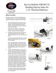
1. Remov<strong>in</strong>g the coil retention nut – You should be<br />
able to loosen the nut by hand (image 2-4). If it is<br />
stuck use a ⁹⁄₁₆” wrench to loosen it.<br />
2. Remov<strong>in</strong>g the coil – Remove the coil by slid<strong>in</strong>g it<br />
off the plunger guide stem (image 2-6).<br />
Caution: If resistance is felt when lift<strong>in</strong>g the coil<br />
Do NOT <strong>in</strong>crease force to remove the coil. Use<br />
a small screwdriver to gently lift it loose from the<br />
<strong>in</strong>sulative layer (image 2-5).<br />
Increased pull<strong>in</strong>g of the coil when resistance is<br />
felt can lead to separation of the Flux plate from<br />
the coil (image 2-7). If separation of the Flux<br />
plate occurs you must replace the coil as further<br />
operation of a coil will lead to premature failure.<br />
Note: You can use a coil with a separated Flux<br />
plate for a short period of time until you can obta<strong>in</strong><br />
a replacement. To operate a valve with a detached<br />
Flux plate, place the Flux plate <strong>in</strong> it’s regular position<br />
on the bottom of the coil when reassembl<strong>in</strong>g<br />
the valve. This should not affect performance, it<br />
just accelerates failure of the coil, as the coils<br />
moisture seal has been compromised.<br />
Image 2-4<br />
CAUTION: If you use a tool<br />
to pry the coil and flux plate<br />
loose, be VERY gentle so you<br />
don’t bend or distort the very<br />
th<strong>in</strong> walled plunger guide tube.<br />
Image 2-5<br />
Flux plate <strong>in</strong>tact<br />
Image 2-7<br />
Image 2-6<br />
Flux plate is separated<br />
- requires<br />
replacement of<br />
the coil<br />
<strong>SB1001.01</strong>-25
3. Remov<strong>in</strong>g the <strong>in</strong>sulation layer – This will<br />
be made of either black foam (image 2-8 &<br />
9) or a thermal barrier washer (image 2-10).<br />
Removal of the black foam may require the<br />
use of a sharp knife to cut around the top<br />
(image 2-8) allow<strong>in</strong>g the top to be removed<br />
(image 2-9).<br />
IMPORTANT: Make sure to keep the<br />
washer or <strong>in</strong>sulative foam for replacement.<br />
Failure to put this layer of “<strong>in</strong>sulation” back<br />
can cause the coil to freeze and lock the<br />
valve <strong>in</strong> an open position caus<strong>in</strong>g a free<br />
flow of cryogenic coolant.<br />
Image 2-10<br />
Image 2-8<br />
Image 2-9<br />
<strong>SB1001.01</strong>-26
4. Remov<strong>in</strong>g the plunger guide – Once the<br />
foam or thermal barrier washer is removed, the<br />
base of the plunger guide will be exposed. The<br />
plunger guide will be one of two k<strong>in</strong>ds, either it<br />
will have two oppos<strong>in</strong>g detents (image 2-11) for<br />
use with a spanner wrench or <strong>Sigma</strong> spanner<br />
nut (image 2-12), or it will not.<br />
If your valve does not have spanner holes,<br />
replace the valve. It is a very old A2025-S26<br />
valve that has given all the service expected<br />
of it.<br />
Always use the a proper spanner wrench or<br />
nut that engages the two detents to open the<br />
valve.<br />
Do NOT use a screwdriver or other object<br />
<strong>in</strong> the slot at the top of the plunger guide<br />
(image 2-14).<br />
That slot is for another purpose. It is very<br />
easy to distort the plunger guide by us<strong>in</strong>g the<br />
screwdriver slot to open the valve. Such distortion<br />
can easily lead to valve failure and a “runaway”<br />
cold condition.<br />
NEVER use any type of tool that grips the<br />
stem of the plunger guide. The guide is<br />
hollow, th<strong>in</strong>, precision mach<strong>in</strong>ed and easily distorted.<br />
Once distorted, it must be discarded.<br />
Place the spanner nut over the valve guide<br />
as shown <strong>in</strong> image 2-12, with the p<strong>in</strong>s <strong>in</strong> the<br />
detents <strong>in</strong> the plunger guide base, and use a<br />
box end wrench to push down and turn <strong>in</strong> one<br />
action (image 2-13). If the valve is mounted <strong>in</strong><br />
the temperature chamber or thermal platform,<br />
use care to avoid bend<strong>in</strong>g mount<strong>in</strong>g brackets,<br />
plumb<strong>in</strong>g, etc.<br />
<strong>Sigma</strong><br />
spanner<br />
nut<br />
Detents<br />
Image 2-11<br />
Image 2-13<br />
Image 2-12<br />
Image 2-14<br />
H<strong>in</strong>t: As you remove the plunger guide it is likely<br />
that the plunger and spr<strong>in</strong>g assembly will fall out.<br />
Use care when remov<strong>in</strong>g the guide so that the<br />
plunger and spr<strong>in</strong>g assembly is not lost.<br />
<strong>SB1001.01</strong>-27
When you remove the plunger guide you will<br />
now be able to see <strong>in</strong>side the valve body<br />
(image 2-15).<br />
5. Remov<strong>in</strong>g the Seal - Whether or not<br />
removal of the seal is required is dependant<br />
on the type of seal.<br />
White or black o-r<strong>in</strong>gs MUST be<br />
replaced each time the valve is opened.<br />
Variseals can be left <strong>in</strong> place 10-15<br />
times without replacement, unless<br />
broken, damaged, or distorted.<br />
The seals are easily removed us<strong>in</strong>g a<br />
f<strong>in</strong>ger nail or a smooth non-sharp <strong>in</strong>strument<br />
(image 2-16) by gently pry<strong>in</strong>g under the seal<br />
and lift<strong>in</strong>g it out (images 2-17 & 18).<br />
Note: A smooth edged staple remover like<br />
the one shown <strong>in</strong> image 2-16 can work as a<br />
seal removal tool.<br />
Image 2-18<br />
Image 2-17<br />
Image 2-16<br />
Image 2-15<br />
<strong>SB1001.01</strong>-28
To Reassemble the valve.<br />
1. Make sure that the valve body, <strong>in</strong>lets, and<br />
outlet orifice are clean and free of debris<br />
(image 2-19).<br />
2. If required place the correct seal (white,<br />
black or Variseal) <strong>in</strong> the base of valve body<br />
(image 2-19).<br />
Note: White and black o-r<strong>in</strong>gs must<br />
be replaced every time the valve is<br />
opened. Variseal o-r<strong>in</strong>gs need only be<br />
replaced every 10-15 open<strong>in</strong>gs, unless<br />
they are broken, damaged, or distorted.<br />
3. Place the plunger and spr<strong>in</strong>g assembly <strong>in</strong><br />
the plunger guide (image 2-20).<br />
4. Thread the plunger guide <strong>in</strong>to place <strong>in</strong> the<br />
valve body.<br />
Image 2-19<br />
Note: Take care to be sure that no<br />
<strong>in</strong>sulat<strong>in</strong>g foam is caught <strong>in</strong> the plunger<br />
guide threads.<br />
Then use a spanner wrench or spanner<br />
nut to tighten the plunger guide to a snug<br />
tightness. A snug tightness is what could<br />
be applied us<strong>in</strong>g a screwdriver; without the<br />
advantage of the lever provided by the long<br />
wrench handle. Note: Do NOT use a screwdriver<br />
to tighten the plunger guide. The<br />
actual specs are 20 <strong>in</strong>ch lbs for “B” size and<br />
25 <strong>in</strong>ch pounds for “D” size.<br />
Image 2-20<br />
Image 2-21<br />
<strong>SB1001.01</strong>-29
5. Replace the black <strong>in</strong>sulative foam or thermal<br />
barrier washer, this is very important to prevent<br />
coil freeze up and cold “run aways”<br />
(image 2-22 or 2-24).<br />
Tip: If you have a valve with black foam<br />
between the body and coil it is recommended<br />
that you replace the foam with a<br />
<strong>Sigma</strong> thermal barrier washer. To do this,<br />
cut the surround<strong>in</strong>g foam flush with the top<br />
of the valve body (image 2-23). Discard<br />
the black foam and replace it with a <strong>Sigma</strong><br />
thermal barrier washer (image 2-24) (part<br />
number 35831 for “B” and 35830 for “D”<br />
valves).<br />
6. Slide the coil onto the plunger guide.<br />
7. Use coil reta<strong>in</strong><strong>in</strong>g nut to hold the coil <strong>in</strong> place.<br />
Tighten to snug tightness only (image 2-25).<br />
Excess tighten<strong>in</strong>g will compress the <strong>in</strong>sulative<br />
layer and can damage the plunger guide.<br />
Foam under the coil should not be compressed<br />
flat, aga<strong>in</strong> we recommend replacement<br />
of the black foam with a <strong>Sigma</strong> thermal<br />
barrier washer.<br />
Image 2-22<br />
Image 2-23 Image 2-24<br />
END<br />
<strong>SB1001.01</strong>-30<br />
Image 2-25