Models C4 & CC-3.5 - with Firmware 7.5.2 - Sigma Systems ...
Models C4 & CC-3.5 - with Firmware 7.5.2 - Sigma Systems ...
Models C4 & CC-3.5 - with Firmware 7.5.2 - Sigma Systems ...
- No tags were found...

Create successful ePaper yourself
Turn your PDF publications into a flip-book with our unique Google optimized e-Paper software.
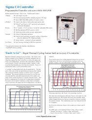
SIGMA SYSTEMSMODELS <strong>C4</strong> & <strong>CC</strong>-3 .5PROGRAMMABLE TEMPERATURE CONTROLLER / INTERFACEOPERATING & PROGRAMMING MANUAL<strong>Firmware</strong> Version <strong>7.5.2</strong>Manual Revision 4June 3, 1999SIGMA SYSTEMS CORPORATION1817 John TowersSan Diego, California 92116 USATEL: (619) 258-3700 WWW.<strong>Sigma</strong><strong>Systems</strong>.Com FAX: (619/258-3712)<strong>C4</strong> Manual Rev <strong>7.5.2</strong>
Copyright 1997, 1998<strong>Sigma</strong> <strong>Systems</strong> Corporation1817 John TowersEl Cajon, California 92020 USAAll rights reservedThe manual may be reproduced, in whole, or in part, solely for the purposes of useand training for the use, of <strong>Sigma</strong> <strong>Systems</strong> equipment, or as required to assist in thesale of new <strong>Sigma</strong> <strong>Systems</strong> equipment. No modification of the content is permitted.<strong>C4</strong> Manual Rev <strong>7.5.2</strong>
TABLE OF CONTENTS1. INTRODUCTION ................................................. 91.1 <strong>Models</strong> <strong>C4</strong> & <strong>CC</strong>-3 .5 Explained ................................. 91.2 General Description ........................................ 101.3 Custom Features / Interchangeability WARNING .................. 111.4 Release <strong>7.5.2</strong> <strong>Firmware</strong> ..................................... 111.5 <strong>C4</strong> vs. <strong>CC</strong>-3 Differences (What’s New) ......................... 121.5.1 Hardware & Stability Improvements ..................... 121.5.2 Hardware Change (EEPROM replaces BBSRAM) .......... 121.5.3 <strong>Firmware</strong> Uploads ................................... 131.5.4 Forced Start from PROM <strong>Firmware</strong> ..................... 131.5.5 Front Panel Information Display at Startup ................ 131.5.6 Temperature Out of Range Shutdown ................... 131.5.7 Internal Error Shutdown Conditions ..................... 141.5.8 Fahrenheit Temperature Scale Supported ................ 141.5.9 Temperature Probe Correction (Calibration) ............... 141.5.10 “Bumpless” Temperature Control ...................... 141.5.11 Intelligent 2 Probe Control (Probe Averaging) ............ 151.5.12 Default Setup Parameters Restore..................... 161.5.13 Program Mode Step Insert & Delete .................... 161.5.14 Program Mode Any Step Points to Step 100 ............. 161.5.15 Program Mode Safer Program Clear ................... 161.5.16 Program Mode Run Time Program Pre-check ............ 161.5.17 Remote Mode EIA-232 Baud Rate Improvement .......... 161.5.18 Remote Mode EIA-232 Port Initialization ................ 171.5.19 Remote Mode Fault Tolerant Parser .............. 171.5.20 Remote Mode System Information Queries .............. 171.5.21 Remote Mode Operation Information Queries ............ 171.5.22 Remote Mode Setup Parameter Commands ............. 181.5.23 Remote Mode IEEE-488 (GPIB) Monitoring .............. 181.5.24 Setup Mode Easier Parameter Access .................. 182. PHYSICAL DESCRIPTION......................................... 192.1 Front Panel ............................................... 192.1.1 Digital LED Display.................................. 192.1.2 LED Indicators ..................................... 192.1.3 Mode Switch ....................................... 202.1.4 Keyboard ......................................... 212.2 Rear Panel Connections .................................... 223. GENERAL OPERATION & ERROR CONDITIONS ...................... 233.1 Startup Displays ........................................... 233.1.1 Model Number and <strong>Firmware</strong> Version Number Display ...... 233.1.2 Temperature Range Display ........................... 233.1.3 Serial Number Display ................................ 24<strong>C4</strong> Manual Rev <strong>7.5.2</strong>3
3.2 Updating <strong>Firmware</strong> ......................................... 243.2.1 Upgrading <strong>Firmware</strong> by PROM Replacement .............. 253.2.2 Upgrading <strong>Firmware</strong> by Uploading through <strong>C4</strong> Serial Port .... 25Making the physical connection for upload ................ 26Running the upload software on the PC .................. 26Starting the upload on the <strong>C4</strong> .......................... 273.3 Restoring Setup Parameters to Default Values.................... 273.4 Fahrenheit Operation ....................................... 28<strong>3.5</strong> System Operating (Temperature) Range ........................ 293.6 Probe Out of Range Shutdown ................................ 293.6.1 Effect of Probe Correction on Out of Range Shutdown ....... 303.6.2 Probe Out of Range Shutdown Reported in Error/Status String................................................. 303.6.3 Clearing a Probe Out of Range Shutdown ................ 303.7 Internal Error Shutdown Conditions ............................ 313.7.1 Watchdog Timer .................................... 313.7.2 Memory signature checking ........................... 313.7.3 Setup parameter integrity checking...................... 323.8 Software Probe Correction (Calibration) ......................... 323.9 Status and Error Reporting ................................... 333.10 Fail-safe System .......................................... 344. INTELLIGENT 2 PROBE CONTROL.................................. 354.1 How Intelligent 2 Probe Control functions ........................ 364.2 Preparing for Intelligent 2 Probe Control ........................ 374.3 Using Intelligent 2 Probe Control .............................. 385. LOCAL MODE ( Basic Operation ) ................................... 395.1 Displaying Temperature ..................................... 395.2 Displaying and Changing the Setpoint .......................... 405.3 Controlling to a Setpoint ..................................... 415.4 Compressor Control ........................................ 426. PROGRAM MODE ............................................... 436.1 Description of a Program Step ................................ 436.1.1 Format of a Program Step............................. 446.1.2 Maximizing Ramp Speed & Other Ramp Considerations ..... 456.2 Clearing Program Memory (Reinitializing program steps)............ 466.3 Displaying Program Steps.................................... 466.4 Entering or Changing a Program Step .......................... 476.5 Insert Program Step ........................................ 476.6 Delete Program step ........................................ 486.7 Running (Executing) a Program ............................... 486.7.1 Program Run Time Information/Considerations ............ 496.7.2 Run Time Pre-read Errors ............................. 49No Probe 2 Error ................................... 504 <strong>C4</strong> Manual Rev <strong>7.5.2</strong>
Invalid Loop Count Error ............................. 50Setpoint Out of Range Error .......................... 506.8 Special Commands ........................................ 506.8.1 Controlled Program Looping ........................... 516.8.2 External Compressor On ............................. 526.8.3 External Compressor Off ............................. 526.8.4 Optional Aux/Power Control Port On .................... 526.8.5 Optional Aux/Power Control Port Off .................... 526.9 Common Programming Issues................................ 536.9.1 Step Numbering .................................... 536.9.2 Changing Substep Values ............................ 536.9.3 Control Ports....................................... 537. REMOTE MODE................................................. 557.1 EIA-232 Interface .......................................... 557.2 IEEE-488 Interface ......................................... 557.3 Command Summary (by functional group) ....................... 567.4 System Information Queries.................................. 577.4.1 QV Query <strong>Firmware</strong> Version........................... 577.4.2 QN Query Controller Serial Number ..................... 577.4.3 QR Query Controller Temperature Range ................ 587.4.4 QS Query Setpoint & Control Probe Number .............. 587.4.5 QF, QFA Query Setup Parameter Value ................ 597.5 Operation Information Queries & Commands .................... 617.5.1 RS, RSA Request Status Byte ......................... 61<strong>7.5.2</strong> RE, REA Request Error Byte .......................... 617.5.3 QE, QEA Query Error/Status String..................... 627.5.4 QC Query Last Command ............................ 647.5.5 ES Enable SRQ (Status Request Mode) ................. 647.5.6 DS Disable the SRQ ................................ 647.5.7 PT Read Temperature ............................... 657.6 Setup Parameter Commands ................................. 667.6.1 SC Set Probe Correction ............................. 667.6.2 WP Set PID Constants .............................. 677.6.3 BF & BO Blower Off & Blower On Commands ............ 687.6.4 SL Set UUT Temperature Limits ....................... 697.6.5 SD Set UUT Temperature Differential Limits .............. 697.6.6 UP Write Current Parameters to NV Memory ............. 697.7 System Operation Commands ................................ 707.7.1 SI Select Immediate Mode............................ 707.7.2 SP Select Program Mode ............................ 707.7.3 PN Select Active (control) Probe ....................... 707.7.4 GT, GTF Go To Temperature ......................... 717.7.5 RA, RAF Ramp to Temperature ....................... 717.7.6 DL Delay (Dwell Interval) ............................. 727.7.7 CO & CF Turn the Refrigeration Port On................. 72<strong>C4</strong> Manual Rev <strong>7.5.2</strong>5
7.7.8 TO & TF Turn Aux/Power Control Port On ................ 727.7.9 QU Quit Controlling ................................. 737.8 Error and Status Reporting - Overview .......................... 747.8.1 Status Byte ........................................ 747.8.2 Error Byte ......................................... 757.8.3 Error/Status String................................... 75Error/Status String Bit Definitions ....................... 778. SETUP MODE................................................... 798.1 Displaying the Field Values................................... 818.2 Changing the Value of a Setup Field ............................ 828.3 Two Probe Mode ........................................... 828.4 Auto-start Mode ........................................... 828.5 Blower Shut-off Mode ....................................... 838.6 Temperature Control Terms (PID) (Setup fields 0, 10, 11, 12) ........ 838.7 Software Probe Correction (Calibration) ......................... 83Entering probe correction setup data .................... 849. APPENDIX ...................................................... 879.1 Programming Examples & Notes .............................. 879.1.1 Simple Local Program Example ........................ 879.1.2 Using shortcuts to shorten program entry time ............. 899.1.3 Local Program Example Using the Special Commands ...... 919.2 Keeping More than One Program in Memory ..................... 939.3 <strong>Sigma</strong> <strong>Systems</strong> <strong>C4</strong> Programming Worksheet ..................... 959.4 Sample Command Structure for IEEE-488 GPIB Operation .......... 969.5 Installation and Use of TTL Outputs and Input .................... 989.6 Field Calibration of Model <strong>C4</strong> Controller ......................... 999.7 Troubleshooting .......................................... 1019.7.1 Servicing Considerations - Service WARNINGS ........... 1019.7.2 Before you go any further.............................. 1019.7.3 Diagnosing and Solving Hardware Problems ............. 1019.7.4 Noise Immunity .................................... 1029.7.5 Diagnosing and Solving Local Mode Problems ............ 102Controller starts immediately in Local Mode.............. 1029.7.6 Diagnosing and Solving Program Mode Problems ......... 102Hard Loops ....................................... 102Explicit Program End ............................... 103Blowers Misbehaving ............................... 103Program hangs on Ramp as Quickly as Possible step ...... 1039.7.7 Diagnosing and Solving Remote Mode Problems .......... 103EIA-232 Problems ................................. 104GPIB IEEE-488 Problems ........................... 1049.7.8 <strong>Firmware</strong> Upload Problems ........................... 104Starting the <strong>C4</strong> from PROM based firmware ............. 105COM port issues................................... 1056 <strong>C4</strong> Manual Rev <strong>7.5.2</strong>
9.8 Temperature Control (PID) Tuning & Problems.................. 105Adjusting for changing needs ......................... 106The Proportional Term .............................. 107The Integral Term ................................. 107The Differential Term ............................... 1089.9 Displayed Messages and Errors Table ......................... 1099.10 Technical Support, Repairs & Returns ........................ 110INDEX .......................................................... 111<strong>C4</strong> Manual Rev <strong>7.5.2</strong>7
8 <strong>C4</strong> Manual Rev <strong>7.5.2</strong>
1. INTRODUCTIONThis manual describes the operating procedures for the <strong>Sigma</strong> <strong>Systems</strong> <strong>Models</strong> <strong>C4</strong>& <strong>CC</strong>-3 .5 Controllers, microprocessor based controllers and control communicationsinterfaces for the family of <strong>Sigma</strong> <strong>Systems</strong> temperature chambers and thermalplatforms.1.1 <strong>Models</strong> <strong>C4</strong> & <strong>CC</strong>-3 .5 ExplainedThe models <strong>C4</strong> & <strong>CC</strong>-3 .5 controllers are successors to the model <strong>CC</strong>-3.The model <strong>C4</strong> is a completely redesigned controller that uses acompletely different and more modern set of internal components <strong>with</strong>a new processor and completely new firmware. Model <strong>C4</strong> controllersare only available as new products from <strong>Sigma</strong> <strong>Systems</strong>.The model <strong>CC</strong>-3 .5 is a hybrid upgrade controller that uses only thedigital circuitry of the model <strong>C4</strong>. It is made by substituting the <strong>C4</strong>digital p.c. board (known <strong>with</strong>in <strong>Sigma</strong> <strong>Systems</strong> as the “CPU board”, orthe “A” board) for the <strong>CC</strong>-3's “A” board. The upgrade from <strong>CC</strong>-3 to<strong>CC</strong>-3 .5 also includes a few small modifications to other internalcomponents. The power supply, power switching, analog, and frontpanel components of the <strong>CC</strong>-3 remain. Model <strong>CC</strong>-3 .5 controllers are onlyavailable as the product of upgrading a <strong>CC</strong>-3 controller.From a functional perspective, models <strong>C4</strong> & <strong>CC</strong>-3 .5 are identical because all of thefunctionality of the controllers is defined by the processor, bus interface components,and firmware... all of which are integral <strong>with</strong> the <strong>C4</strong> “A” board. The <strong>C4</strong> analog andfront panel components that remain unique to the <strong>C4</strong> (not included in the <strong>CC</strong>-3 .5upgrade from <strong>CC</strong>-3) provide slightly better accuracy and substantially better noiseand static immunity.For the balance of this manual, the term <strong>C4</strong> will mean toinclude both the model <strong>C4</strong> controller and the model <strong>CC</strong>-3 .5controller. In the event that there is a difference betweenthe two models, that difference will be explicitly detailed.<strong>C4</strong> Manual Rev <strong>7.5.2</strong>9
1.2 General DescriptionUsing the model <strong>C4</strong>, temperature control is available manually from the frontpanel, by use of user entered programs, or via remote control via either a EIA-232or IEEE-488 GPIB. The controller has a precision temperature reading capability<strong>with</strong> a digital read-out. Two temperature probes can be connected to thecontroller allowing either probe or both probes to be the control probe(s) whileeither probe can be used to take measurements.Two additional controlled device ports are available. They are intended for on/offcontrol of a refrigeration compressor and an external load such as a device undertest, or a main chamber or platform power relay. These ports normally aresupplied as TTL level (low voltage) ports but are optionally available <strong>with</strong> solidstate relays to control line voltage as in the case of units <strong>with</strong> mechanicalrefrigeration. The compressor control port may be toggled from the front panel atany time in the manual (LOCAL) mode. The compressor is designed to not cycleon and off <strong>with</strong> the temperature control function.The controller operates in each of four modes:LocalModeProgramModeRemoteModeSetupModeSingle Setpoint control from the front panel. SimpleStart/Stop functionality.Programmed control using programs entered, stored, andrun from the front panel. 100 Temperature/DurationProgram steps available. Multiple programs may be storedand called as needed.Control via EIA-232 or IEEE-488 GPIB. The IEEE-488interface implementation is a TALKER/LISTENER <strong>with</strong>serial poll. Extended addressing and parallel pollcapabilities are not supported. The EIA-232 interface isfully configurable for baud rate, data bits, stop bits andparity.Used to define and store operation and environmentvariables that control how the C-4 behaves.10 <strong>C4</strong> Manual Rev <strong>7.5.2</strong>
1.3 Custom Features / Interchangeability WARNINGEach <strong>Sigma</strong> <strong>Systems</strong> <strong>C4</strong> Controller has been custom configured for the chamber orplatform <strong>with</strong> which it was supplied or for which it was specified. Many unitsinclude special wiring for custom control applications, precision fail-safe additions,non-standard voltages, external unit power control, etc. Units that may appearto be identical may be internally quite different. Do not interchangecontrollers between controlled devices (chambers and/or platforms)unless you are certain that the controllers have been identicallyconstructed.Failure to heed this warning voids your warranty, may cause unpredictablecontrolled device behavior that could cause damage to persons or property, pose arisk of fire, or cause other problems. If you must move controllers betweencontrolled devices, please contact the <strong>Sigma</strong> technical support department forassistance and advice.1.4 Release <strong>7.5.2</strong> <strong>Firmware</strong>This manual is specifically written to cover the features of Release <strong>7.5.2</strong> firmwarefor the <strong>Sigma</strong> <strong>Systems</strong> Model <strong>C4</strong> controller. The features of this release firmwareare largely backward compatible <strong>with</strong> all <strong>CC</strong>-3 and earlier <strong>CC</strong>-3 .5 & <strong>C4</strong> firmware.This release fixes a number of bugs found in the <strong>CC</strong>-3 .5 interim release versions6.8.6, 6.9.0, and 7.0.0. It also adds a number of new features. See Section 1.5.Note: This release implements probe temperature correction on a perprobe basis. Interim <strong>CC</strong>-3 .5 releases implemented this feature on a globalbasis.<strong>Sigma</strong> highly recommends that all users update to the latest firmware release.Contact <strong>Sigma</strong> Technical Support. See Section 9.10.Note: This release is not available as an upload file for serial port firmwareupdating of your controller. Due to non-backward compatible change in the waysome data is stored internally, this version must be installed using a PROMobtained from <strong>Sigma</strong> <strong>Systems</strong>.<strong>C4</strong> Manual Rev <strong>7.5.2</strong>11
1.5 <strong>C4</strong> vs. <strong>CC</strong>-3 Differences (What’s New)1.5.1 Hardware & Stability ImprovementsThe new <strong>C4</strong> introduces a number of new improvements to make the controllerfaster and more reliable than its predecessor.The <strong>C4</strong> has a completely new digital processing board. The new board has a muchfaster processor, more memory, and a much faster IEEE-488 GPIB controller.Interrupts have been completely restructured to improve stability. The multilayerdesign is far more tolerant of both static and power line interference. There isnow a watchdog timer to detect system lockups in the event that something doesinterfere <strong>with</strong> the system. The battery backed RAM has been replaced by anEEPROM. The Vactrol type isolation device in the failsafe circuit has beenreplaced. The <strong>C4</strong> contains no components that have a time based failure mode.The new firmware also monitors the state and integrity of internal memory.Critical system information is stored in multiple places so that minor errors due touncontrollable transients or other causes can be repaired on the fly <strong>with</strong> nodisruption in process control. Likewise, both the front panel display and the GPIBinterface are monitored constantly to assure that their operation has not beencompromised by static discharge or line transient. In the event of a problem,either device can be reset on the fly to allow operations to continue normally.System integrity is further enhanced by a series of successive shutdown processesthat monitor the integrity of the data coming from the sensor probes. In the eventthat any probe reports a temperature more than 20/C beyond the limits set in thecontroller, the controller will shut down all heating and cooling and display awarning message. Likewise, in the event that a sensor probe reports an extremetemperature, either hot or cold, the system will assume that a probe has becomecompromised by an open or shorted circuit and stop applying heat and cooling,shut down the system and display an appropriate warning message..1.5.2 Hardware Change (EEPROM replaces BBSRAM)All <strong>C4</strong> controllers and <strong>CC</strong>-3 .5 controllers converted after January 1998 have thebattery backed static RAM (BBSRAM) replaced <strong>with</strong> an EEPROM. This changewas implemented to reduce the possibility that the controller will require service.Although changing the BBSRAM when the battery died (about every 5-12 years)was a fairly simple matter, the necessity for doing so was found to be a nuisanceas was diagnosing the need for the change. The BBSRAM or EEPROM providesthe non volatile memory where the <strong>C4</strong> stores both the setup parameterinformation and the user programs.12 <strong>C4</strong> Manual Rev <strong>7.5.2</strong>
1.5.3 <strong>Firmware</strong> UploadsWhen new firmware is available for your <strong>C4</strong>, you can easily upload it into thecontroller using the controller’s serial port. The procedure requires only a diskettebootable PC and a serial cable and takes only about ten minutes. <strong>Firmware</strong>updates, when available, may be obtained on diskette for a fee from <strong>Sigma</strong><strong>Systems</strong> or for free by download from www.<strong>Sigma</strong><strong>Systems</strong>.Com orftp.<strong>Sigma</strong><strong>Systems</strong>.Com. See Section 3.2.21.5.4 Forced Start from PROM <strong>Firmware</strong>The controller can be started from the original firmware version that is stored inthe PROM. Uploaded versions are stored in flash memory. If a firmware uploadsession should go astray somehow, this feature allows the controller to stilloperate. See Section 9.7.8.1.5.5 Front Panel Information Display at StartupThe controller model is displayed at startup - See Section 3.1.1The firmware version number is displayed at startup - See Section 3.1.1The operating range may be displayed at startup - See Section 3.1.2The controller serial number may be displayed - See Section 3.1.31.5.6 Temperature Out of Range ShutdownThe controller now stores the operational limits for itself, the controlled device(<strong>Sigma</strong> chamber or platform), and the unit under test (UUT). The operatingtemperature is checked against these limits, if it is too far outside these limits,.the system is shutdown <strong>with</strong> an appropriate error message displayed. SeeSection <strong>3.5</strong>.<strong>C4</strong> Manual Rev <strong>7.5.2</strong>13
1.5.7 Internal Error Shutdown ConditionsThe <strong>C4</strong> monitors system health by keeping track of three additional areas;they are:Processor healthMemory conditionSetup parameter tableTracked by watchdog timerChecked at startupChecked continuously as usedSome detected internal errors can be repaired on the fly. If this is possible, the <strong>C4</strong>will recover from the error and you will not know the error existed. If, however,the error is not repairable and the system must be shut down, an error messagewill be displayed to help you understand what happened and how to prevent orcope <strong>with</strong> it. See Section 3.7.1.5.8 Fahrenheit Temperature Scale SupportedThe controller will now operate in either Celsius /C or Fahrenheit /F mode. SeeSection 3.4.1.5.9 Temperature Probe Correction (Calibration)The <strong>C4</strong> will allow you to enter data via the Setup mode that will correct anomaliesin the temperature readings and control. Such adjustments are sometimesnecessary to optimize accuracy at a particular temperature, or to compensate fordifferences between raw probe temperature data and actual temperatures. Thesedifferences can be the result of probe placement, effects of the unit under test onthe temperature data, or other causes. See Section 3.81.5.10 “Bumpless” Temperature Control(Not in this release. Available in next release, <strong>with</strong>out charge. Check the<strong>Sigma</strong> <strong>Systems</strong> FTP or WWW site for downloadable file.)When the setpoint is changed, the PID control algorithm begins a new “search” forthe right amount of heat and/or cooling to maintain the new setpoint. Normally,for each new setpoint, the PID routines begin the search anew... behaving as if thecontroller was just turned on. The controller will quickly determine that heat orcooling is called for, and while the chamber or platform advances toward the newSetpoint, the PID routine adjusts for the response to heat and cool andmethodically settles the chamber or platform in on the new setpoint. For mostsetpoint changes, where the new and old setpoints are quite different, this is afast, accurate and appropriate method of control.14 <strong>C4</strong> Manual Rev <strong>7.5.2</strong>
However, when the change in the Setpoint is very small, this “start from thebeginning” search routine can search over such a wide range that it will introducea “bump” in the platform or chamber temperature that can exceed the amount ofthe Setpoint change. The <strong>C4</strong> includes an intelligent PID routine that constrainsthe search appropriately for the change in Setpoint and thus eliminates the “PIDbump”.1.5.11 Intelligent 2 Probe Control (Probe Averaging)(Not in this release. Available in next release, <strong>with</strong>out charge. Check the<strong>Sigma</strong> <strong>Systems</strong> FTP or WWW site for downloadable file.)Intelligent 2 Probe Control allows the internal temperature of the unit under test(UUT) to be used in the temperature control algorithm. Both the primary probe,located in the chamber airstream or platform, and the secondary probe, typicallylocated inside the UUT, are used to provide a chamber or platform response thatcan accelerate testing while respecting the absolute and relative limits of all theaffected components.Common single probe control strives to maintain the Setpoint temperature in thechamber airstream, or at the platform surface. If the UUT is massive, or is a poorthermal conductor, the internal temperature of the UUT can lag the chamber orplatform temperature considerably. Conversely, using a second probe, buriedinside the UUT, to control the temperature may achieve better UUT interiortemperature control, but it will do so at the risk of extreme temperatures in thechamber or on the platform. If not carefully monitored, second probe only controlcan result substantial damage to the chamber or platform and UUT and riskoperator injury.Intelligent 2 Probe Control is designed to achieve the Setpoint temperature insidethe UUT (probe 2) either as quickly as possible, or at a controlled ramp rate, whilealways respecting the limits of the controller, chamber or platform, and UUT. Theuser may specify the absolute limits of the exterior of the UUT as well as limitthemal shock by specifying a dynamically changing “sliding scale” maximumtemperature differential for the UUT skin to core temperature. Intelligent 2Probe Control will maximize speed in achieving internal UUT Setpointtemperatures, while, at the same time, controlling the thermal stress on the UUT.An in depth discussion of this feature can be found in Section 4.1.5.12 Default Setup Parameters RestoreThere is a procedure for erasing the current setup parameter table data andrestoring it basic default values. See Section 3.3<strong>C4</strong> Manual Rev <strong>7.5.2</strong>15
1.5.13 Program Mode Step Insert & DeleteProgram steps may now be deleted from or inserted into programs.See Sections 6.5 & 6.6.1.5.14 Program Mode Any Step Points to Step 100Any program step may now point to step 100 (program end) as the next step toexecute.1.5.15 Program Mode Safer Program ClearSome deliberate delays have added to the key sequence to completely clear theprogram memory to lessen the likelihood that all of program memory will beerased by accident.1.5.16 Program Mode Run Time Program Pre-checkWhen a program is run in Program Mode, the <strong>C4</strong> pre-reads the program to lookfor run-time errors that it can report to you before starting. By pre-checking yourprogram, errors are dealt <strong>with</strong> immediately rather than after the program haspartially completed. The following items are checked:Calls for probe 2 when only one probe is defined for the systemCalls for setpoints that are not <strong>with</strong>in the system operating rangeLoop counter numbers not <strong>with</strong>in the range of 1 to 999 integerSee Section 6.7.2 for a full explanation.1.5.17 Remote Mode EIA-232 Baud Rate ImprovementEIA-232 communications are now supported at 19,200 and 38,400 bps.See Section 8.16 <strong>C4</strong> Manual Rev <strong>7.5.2</strong>
1.5.18 Remote Mode EIA-232 Port InitializationThe <strong>CC</strong>-3 required that to use the EIA-232 port, the port had to be initialized byswitching the mode switch to SETUP before switching to REMOTE mode. The <strong>C4</strong>eliminates this requirement. The EIA-232 port is initialized each time the remoteswitch is switched to REMOTE mode.1.5.19 Remote Mode Fault Tolerant ParserThe <strong>C4</strong> uses a very fault tolerant parser. Command strings received over eitherthe EIA-232 or GPIB ports are converted to upper case, extra spaces and tabs areremoved, commas are converted to spaces and line terminators are corrected ifnecessary. For this reason, programs that work properly <strong>with</strong> the <strong>C4</strong> and not <strong>with</strong>a <strong>CC</strong>-3, that use only <strong>CC</strong>-3 commands, probably have syntax errors that the <strong>C4</strong>parser corrects. See Section 9.7.71.5.20 Remote Mode System Information QueriesQV Query <strong>Firmware</strong> Version ..................... See Section 7.4.1QN Query Serial Number ........................ See Section 7.4.2QR Query Temperature Range .................... See Section 7.4.3QS Query Setpoint & Control Probe Number ........ See Section 7.4.4QF Query Setup Parameter Data (Binary Query)..... See Section 7.4.5QFA Query Setup Parameter Data (ASCII Query) ..... See Section 7.4.51.5.21 Remote Mode Operation Information QueriesRSA Request Status Byte (ASCII Query) ............. See Section 7.5.1REA Request Error Byte (ASCII Query) ............. See Section <strong>7.5.2</strong>QE Query Error/Status String (Binary Query) ....... See Section 7.5.3QEA Query Error/Status String (ASCII Query) ........ See Section 7.5.3QC Query Last Command........................ See Section 7.5.4<strong>C4</strong> Manual Rev <strong>7.5.2</strong>17
1.5.22 Remote Mode Setup Parameter CommandsSC Set Correction (Calibration) for Probe ........... See Section 7.6.1WP Set PID Constants ........................... See Section 7.6.2BF Turn Blowers Off ............................ See Section 7.6.3BO Turn Blowers On ............................ See Section 7.6.3SL Set UUT Temperature Limits.................. See Section 7.6.4SD Set UUT Temperature Differential Limits........ See Section 7.6.5UP Write SRAM Parameters to EEPROM ........... See Section 7.6.61.5.23 Remote Mode IEEE-488 (GPIB) MonitoringThe IEEE-488 bus controller is automatically reset if a problem is detected. Nomessage to the user is generated as no data is typically lost in the process.1.5.24 Setup Mode Easier Parameter AccessSetup parameters may now be accessed directly by number rather than having toscroll the entire list. If scrolling is used, there is now a backup key so the list canbe scrolled in either direction. Likewise, for parameters that are chosen from alist, the list can be scrolled in either direction or the parameters can be keyed indirectly <strong>with</strong>out scrolling the list. See Section 8.1.18 <strong>C4</strong> Manual Rev <strong>7.5.2</strong>
2. PHYSICAL DESCRIPTIONThe SIGMA SYSTEMS Model <strong>C4</strong> Controller fits into an area <strong>3.5</strong>" x 5.5" x 9.5"long. Connection to the chamber or platform is made through an umbilical cable<strong>with</strong> a 12 pin connector that is standard for all SIGMA chambers and thermalplatforms. Controllers destined for use <strong>with</strong> SIGMA thermal platforms have anadditional 6 pin connector used for the sensor probe circuits. All <strong>C4</strong> controllershave a 3 pin “pigtail” connector at the back of the controller for control ofrefrigeration via solid state relay. This feature was optional on <strong>CC</strong>-3 controllersand is thus not a consistent feature of <strong>CC</strong>-3 .5 controllers.2.1 Front PanelThe front panel consists of four major parts: the LED digit display, the LEDindicators, the mode switch and the keypad. The numbers in circles on the frontpanel guide the user through the steps for changing the temperature setting inthe LOCAL (manual) mode of operation. See Section 5.2.1.1 Digital LED DisplayThe Digital LED Display is a 7 digit display arranged in the followingconfiguration:***-****The display is used for showing probe temperatures, setpoints, program steps,fail-safe status and setup information.2.1.2 LED IndicatorsBelow the Digital LED Display are four discrete LED Indicators. These indicatorsare arranged in the following order:REFERCOOLHEATRUNREFER indicator lights if power is applied to the refrigeration compressorcontrol port (not all units are equipped <strong>with</strong> compressors).<strong>C4</strong> Manual Rev <strong>7.5.2</strong>19
COOL indicator lights when cooling is active, typically during the time thecryogenic valve is open on cryogenically cooled units.HEAT indicator is pulsed along <strong>with</strong> the on and off function of the heaters.These indicators are active in all modes of operation.RUN indicator shows whether the chamber temperature is being controlled.2.1.3 Mode SwitchThe Mode Switch is used to apply power to the chamber and to select the mode ofoperation. It is a 5 position rotary switch arranged as follows:The OFF position removes the power from heating and cooling and compressorcontrol circuits of both the controller and the chamber or thermal platform.CAUTION: Placing the mode switch in the OFF positiondoes not remove all power from either the controller or thechamber or thermal platform. Only the heating, cooling,and compressor control circuits are turned off. Full linevoltage potential is still available in many places in both thecontroller and the chamber or platform. See servicingwarnings and instructions in the appendix of this manual.Moving the rotary switch changes the mode of operation of the chamber. Thedifferent modes are described in detail in separate sections of this manual. Whenthe rotary mode switch is moved to a new position, other than OFF, thetemperature control loop, if running, is turned off, heating and cooling aredisabled but the chamber blowers will continue to run unless disabled via setup20 <strong>C4</strong> Manual Rev <strong>7.5.2</strong>
parameter F15. Likewise, at the end of a local or remotely controlled program,chamber blowers will continue to run, but heating and cooling will be disabled.Note that a chamber in this condition, <strong>with</strong> blowers running, will exhibit someheating due to blower air friction. This effect is exaggerated in units equipped<strong>with</strong> high velocity blowers. Moving the rotary switch between OFF and LOCALwill maintain the last used setpoint for the next operation of the controller. See6.3 for description of auto-start function.2.1.4 KeyboardThe keyboard consists of 20 momentary contact keys. Certain keys are functionalonly in some of the modes of operation. With some keys, such as the DisplayControl, the function is different depending on the mode of operation. TheKeyboard is arranged in the following configuration:1 2 3CLEARPROGSTARTSTOP4 5 6 REFER ENTER7 8 9 ADVDISPTEMP. 0+-CLEARENTRYDISPCNTLCLEAR PROG Clear program from memorySTART STOP Start/Stop temperature controlREFER Toggle refrigeration compressor on or off *ENTEREnter/finalize current keyboard entryADVAdvance to next program stepDISP TEMP Display temperatureCLEAR ENTRY Clear current keyboard/display entryDISP CNTL Display control setpoint* = LOCAL MODE ONLY.<strong>C4</strong> Manual Rev <strong>7.5.2</strong>21
2.2 Rear Panel ConnectionsAt the rear panel of the controller, a cable is provided to connect to the power,cooling solenoid, mechanical refrigeration and heaters of the chamber. Inaddition, a six lug screw terminal block (J1) is provided for eyelet terminalconnection of the temperature probes and for connection of one additional optionaldevice such as the <strong>Sigma</strong> PFS-2 Precision Fail Safe.J1 TOPìíîïðñProbe 1 (Black lead)Probe 2 (Black lead)Chassis Ground (Probe shield)(Chamber or platform ground, etc.)Probe 1 & 2 return (Red or White lead)Auxiliary device ground12 VDC for Fail-SafePlease observe all standard anti-static procedures when making connections tothese points!There is also an IEEE-488 (GPIB) connector, series 57 (metric threads), and anEIA-232 connector, female DB-25, for the remote modes of operation. Two TTLoutputs and one TTL input are also available on J6. (See Section 9.5)22 <strong>C4</strong> Manual Rev <strong>7.5.2</strong>
3. GENERAL OPERATION & ERROR CONDITIONS3.1 Startup Displays3.1.1 Model Number and <strong>Firmware</strong> Version Number DisplayThe <strong>C4</strong> identifies itself upon power up. It will display the model number for 1second, then the firmware version number for 2½ seconds as follows:c3-5 rel <strong>7.5.2</strong>c4 rel <strong>7.5.2</strong>3.1.2 Temperature Range DisplayEach <strong>C4</strong> controller is set at the factory for use <strong>with</strong> a specific device (chamber orplatform). Because the controlled device was made to specific thermal limitspecifications, and because constraining the operating range of the controllerimproves it’s accuracy, the controller to be used <strong>with</strong> each device is set to operateonly <strong>with</strong>in the range appropriate for that device. The setting of an operatingrange involves a number of internal adjustments and calibrations and the loadingof specific control tables for that range. This setting can only be changed by<strong>Sigma</strong> <strong>Systems</strong> service personnel. We recommend that each controller be kept<strong>with</strong> the device for which it was originally configured.However, if you find that it is necessary to move a controller to another device, itis important that you check to be sure that the controller that is moved isconfigured to operate in the appropriate range for the device it is to control. As ofNovember, 1998, controllers are supplied for five ranges as follows:-100/C to 200/C -148/F to 392/F -100/C to 300/C -148/F to 572/F-100/C to 350/C -148/F to 662/F -175/C to 400/C -283/F to 752/F-195/C to 300/C -319/F to 572/FTo check the internal range setting of your <strong>C4</strong> controller, turn the mode switchfrom OFF to any other position. During the 2½ seconds that the firmware releasenumber is shown on the display, rapidly press three times. Theinternal range setting will be displayed for 5 seconds following the version display.An example:200 - 100c 392 - 148f(Celsius mode)(Fahrenheit mode)<strong>C4</strong> Manual Rev <strong>7.5.2</strong>23
3.1.3 Serial Number DisplayThe controller serial number can be displayed at startup by pressing while the model number (c3-5 or c4) is displayed. The serialnumber will be displayed in the format:4-0 3276The first digit (either a 3 or 4) indicates whether the controller is a <strong>CC</strong>-3 .5 or <strong>C4</strong>,and the 5 digits to the right of the dash is the sequential part of the number.There is no significance to the leftmost of the 5 sequential digits being separatedfrom the other 4 digits. The separation is a limitation of the display. Whenrecording or reporting serial numbers, please always use the 7 digit string,including the leftmost digit and the dash in this format: 4-03276.When the serial number is displayed, the controller is not controlling. Thenumber will remain on the display until the controller is turned off.3.2 Updating <strong>Firmware</strong>There are two methods of updating the firmware in the <strong>C4</strong>..1. Physically replace the EEPROM that contains the firmware.(There is usually a charge for firmware EEPROMs)2. Use a PC to upload the firmware through the <strong>C4</strong> serial port.(<strong>Firmware</strong> and upload software are free from <strong>Sigma</strong>System’s internet sites, www.<strong>Sigma</strong><strong>Systems</strong>.com orftp.<strong>Sigma</strong><strong>Systems</strong>.com)Note: All firmware updates are available on EEPROM chips for physicalinstallation. Not all updates are available as downloads from the <strong>Sigma</strong> <strong>Systems</strong>web site. The reason for this is that some firmware updates make changes in thebasic data structures inside the <strong>C4</strong>. Because firmware loaded into the <strong>C4</strong> throughthe serial port is stored separately, and in addition to, the EEPROM firmware,and because the <strong>C4</strong> can be started from either resident version, the two versionsmust use compatible data structures. Thus, versions that will modify the datastructures in the <strong>C4</strong> may only be installed by changing the firmware EEPROM.24 <strong>C4</strong> Manual Rev <strong>7.5.2</strong>
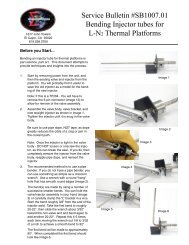
3.2.1 Upgrading <strong>Firmware</strong> by PROM ReplacementBefore starting, be certain that you have a properly grounded antistaticsurface and a grounding strap to prevent damaging the <strong>C4</strong> componentsduring disassembly and reassembly.Remove the <strong>C4</strong> from its cabinet or rack, then remove the EEPROM chip thatcontains the firmware and replace it <strong>with</strong> a new one containing the updatedfirmware. <strong>Firmware</strong>EEPROMs are availablefrom <strong>Sigma</strong> <strong>Systems</strong>.There is a charge forfirmware EEPROMs.The firmware EEPROMis located on the digital or“A” board, the same boardthat has the EIA-232 andGPIB connectors on theend. The location of thefirmware EEPROM isshown by the trianglepointer. The EEPROMsocket is labeled U13. Make certain that the end of the EEPROM <strong>with</strong> the notchor notch mark is toward the inside, or center, of the board.Note that it is possible to remove and replace the firmware EEPROM <strong>with</strong>outdisassembling the <strong>C4</strong>. If you lay the controller upside down, and look at thedigital board from the bottom, the firmware EEPROM is the first large chip fromthe front of the controller. You will not be able to see the U13 label, but you cansee the C32 label on the small capacitor located next to the firmware EEPROMsocket. Using a small flat bladed screwdriver or chip removal tool, carefully prythe old EEPROM from it’s socket. Try to keep the chip as flat as possible whileremoving it to prevent damage to the pins or socket. When replacing, keep thereplacement EEPROM flat to the socket, make sure all pins are started in theirrespective receivers in the socket, then press the chip firmly into place.3.2.2 Upgrading <strong>Firmware</strong> by Uploading through <strong>C4</strong> Serial PortNote: <strong>CC</strong>-<strong>3.5</strong> controllers <strong>with</strong> version 7.0.0 firmware or earlier have batterybacked RAMS for non volatile storage. These units MUST have the BBRAMreplaced <strong>with</strong> an EEPROM before newer firmware is installed.<strong>C4</strong> Manual Rev <strong>7.5.2</strong>25
Use a DOS bootable diskette and a PC type computer to load the new firmwarethrough the <strong>C4</strong>'s serial port. You can obtain the required diskette from <strong>Sigma</strong><strong>Systems</strong> for a fee, or you can provide your own DOS bootable diskette and obtainthe necessary files for the upload process from the <strong>Sigma</strong> <strong>Systems</strong> site on theInternet. The Internet address for this site is:www.<strong>Sigma</strong><strong>Systems</strong>.comThe download file, SSUPxxxx.EXE, may contain specific instructions that replacethe instructions in the next paragraph. After downloading the file, copy it to anotherwise empty DOS bootable diskette and run SSUPxxxx.EXE. This file is aself extracting ZIP archive that will install all the files you need onto the diskette.Check for the presence of a README.TXT file on the diskette for instructions thatsupplement or supercede these instructions.Making the physical connection for uploadTo upload firmware to your <strong>C4</strong>, you will need to connect the <strong>C4</strong> to a DOS bootablePC compatible computer using a straight-through, or modem type serial cable.The <strong>C4</strong> is configured as DCE (Data Communications Equipment). Therefore, doNOT use a “null modem” type serial cable that has pins 2 & 3 crossed. Connectthe cable to either COM1 or COM2 on the PC and to the female DB25 connectoron the back of the <strong>C4</strong>.Running the upload software on the PCAfter you run the SSUPxxxx.EXE file on your DOS bootable diskette you areready to run the software. Place the floppy in the “A” drive of the PC and turn onor reset the PC to allow it to boot from the floppy. Follow the instructions on thescreen. Note that the menu will allow you to do successive uploads <strong>with</strong>outrestarting and will allow you to change serial ports as you do so. Users who willbe uploading to a number of controllers in one session will find that this featuresaves some time.If the uploads are being done on a bench (as opposed to leaving the controller init’s chamber or platform housing), be certain to follow all precautions aboutremoving all power before removing the controller and about taking care to useproper anti-static procedures when handling the controller. Be certain that thebench has a properly grounded anti-static surface.If you are going to upload firmware into many controllers successively in a benchenvironment, you can use a PC <strong>with</strong> two serial ports (COM1 and COM2) and twoserial cables. You can then have the upload program alternate serial ports for the26 <strong>C4</strong> Manual Rev <strong>7.5.2</strong>
uploads so that you can upload to one controller while connecting anddisconnecting the other.Starting the upload on the <strong>C4</strong>When the PC is ready, turn the <strong>C4</strong> controller on. During the 1 second display ofthe model number, rapidly press three times. The display willread:rs loadThe firmware upload should begin immediately. The PC will indicate when theload is complete.If you have difficulties, see the trouble shooting information in Section 9.7.8.3.3 Restoring Setup Parameters to Default ValuesNote: The default values are very generic. They are not the values that werelikely in the controller when it was shipped from the factory. After completingthis procedure, please check each value to make certain that it is appropriate.To restore the default values to the setup parameter table, turn the controller off,then back on. During the 1 second in which the controller model is displayed,press very quickly 3 times. The display should then readsu resPress to confirm that you want restore the default values. (Any otherkey will abort the process). The display should then readee busy and then su doneTurn the controller off, then on again to resume operation <strong>with</strong> the new values.The first time the controller is turned back on after restoring the default setupparameters, the display will show all res . The mode switch must then beturned to SETUP. (You may see an ee busy display and model numberand/or firmware version number at this time.) The controller forces you to SETUPmode before it will function as a reminder that the default values have beenloaded and that the parameters needed for your operation have not yet been set.<strong>C4</strong> Manual Rev <strong>7.5.2</strong>27
When you have set the necessary parameters for your needs, you are ready to goto LOCAL, PROGRAM, or REMOTE mode.28 <strong>C4</strong> Manual Rev <strong>7.5.2</strong>
3.4 Fahrenheit OperationThe <strong>C4</strong> can use either Celsius or Fahrenheit temperature scales. Celsius is thedefault mode. When the controller is operating in Celsius mode it’s behavior isidentical to the model <strong>CC</strong>-3 controller. When the controller is operating inFahrenheit mode, both the displays and the bus communications are different.These differences are intentional and designed to prevent errors that might arisefrom a user using setpoints in one scale while the controller is operating in theother scale. Note, however, that there is no difference in the Program modeprogramming operation of the <strong>C4</strong> when operating in either Fahrenheit or Celsiusmode. It is incumbent upon the user to notice the differences in the temperaturedisplays and program accordingly.To change the temperature scale, use SETUP mode (See Section 8) to access setupparameter F16. Select either of these field values:0 Celsius1 FahrenheitWhen in Fahrenheit mode, temperature displays have an “F” following the probeidentifier on the left side of the display. Example:p1f 102.4Likewise, temperature inquires over the bus (PT command - See Section 7.5.7)will return a string <strong>with</strong> an “F” as the third byte in the string. The string willtherefore be 1 byte longer than the string returned in Celsius mode. Thisdifference was intentional as it requires a modification of the parsing routine thatwill assure that Celsius and Fahrenheit data are recognized properly. Thus, if thecurrent probe 1 temperature is 86.7/F, the result of a Fahrenheit mode gettemperature query for probe 1 (query command = PT1) would beT1F 86.7If the temperature at probe 1 was 55.4/C, the same command in Celsius modewould returnT1 55.4During Remote mode operation, the <strong>C4</strong> may be queried to determine the currenttemperature scale by using the QS, Query Setpoint, command. See Section 7.4.4.<strong>C4</strong> Manual Rev <strong>7.5.2</strong>29
<strong>3.5</strong> System Operating (Temperature) RangeThe <strong>C4</strong> controller operates <strong>with</strong>in the limits of the system devices. There are 3pairs (low-high) of temperature limits that constrain the range of operations.1. The range of the <strong>C4</strong> as it is set at the factory2 The range of the controlled device (chamber or platform) asdescribed by setup parameters F25 & F26.3 The range of the UUT (unit under test) as described bysetup parameters F27 & F28.Each of these ranges is characterized by a low limit and a high limit. The highestof the 3 low limits is the low temperature System Operation Limit. The lowestof the 3 high limits is the high temperature System Operation Limit. In otherwords, the controller will respect the most restrictive limits that are described bythe combination of the 3 ranges listed above.The low and high temperature System Operating Limits define the SystemOperating Range. The controller will not accept setpoints outside the SystemOperating Range and will report error conditions and stop controlling if thecontrolling probe(s) report a temperature too far outside that range.Note: Probe 1 is always in the chamber airstream or platform and is alwaysmonitored for conformance <strong>with</strong> the System Operating Range. Probe 2 ismonitored for conformance only if it is being used for control.3.6 Probe Out of Range ShutdownWhen the <strong>C4</strong> is actively controlling the temperature of a chamber or platform, itfrequently checks to be certain that the control temperature, as reported by anyactive control probe, is <strong>with</strong>in the System Operating Range.In the event that the temperature reported by the active control probe is morethan 20/C, and less than 50/C, outside the controller’s System Operating Range,then the controller will presume that a “run away” condition exists. The controllerwill turn off all heating and cooling and stop controlling. Blowers will be left inthe condition determined by setup parameter F15 (Blower shut-off mode). Thecontroller display will showp1 lop1 hi30 <strong>C4</strong> Manual Rev <strong>7.5.2</strong>
“LO” indicates that the reported temperature was 20-50/C below the SystemOperating Range. “HI” indicates that the reported temperature was 20-50/Cabove the System Operating Range. The number following the p is the number ofthe probe that reported the excessive temperature.In the event that the control temperature reported by the active control probe ismore than 50/C beyond the System Operating Range, the controller will presumethat the operation of the probe has been compromised by an open or shortedcircuit. The controller will turn off all heating and cooling and stop controlling.Blowers will be left in the condition determined by setup parameter F15 (Blowershut-off mode). The controller display will showp1 errp1 -errThe minus sign in the display indicates that the reported temperature was belowthe System Operating Range and the absence of the minus sign indicates that itwas above the System Operating Range.Note that because the <strong>C4</strong> will report a hi or lo condition and stop controllingfor an error of 20-50/C, the only events that will typically trigger an err or -err condition is a instantaneous failure of the sensing circuit, most likely anopen circuit (err ) or short (-err ).3.6.1 Effect of Probe Correction on Out of Range ShutdownAny adjustments to the probe readings made by the Software Probe Correctionfeature (See Section 3.8) will not affect system over/under temperature shutdownoperations. The raw (uncorrected) probe readings for the current active controlprobe(s) are used for the system health monitoring.3.6.2 Probe Out of Range Shutdown Reported in Error/Status StringAny Probe Out of Range Shutdown will set a bit in Byte 03 of the Error/StatusString. See Section 7.8.3 for specific bit assignments.3.6.3 Clearing a Probe Out of Range Shutdown<strong>C4</strong> Manual Rev <strong>7.5.2</strong>31
The Probe Out of Range Shutdown condition can be cleared by pressing in Local or Program mode, by rotation the mode switch on thefront panel to a different position, or by issuing a Device Clear in Remote mode.3.7 Internal Error Shutdown ConditionsThe <strong>C4</strong> monitors system health by keeping track of four internal areas; they are:Processor healthMemory conditionSetup parameter integrityIEEE-488 bus integrityTracked by watchdog timerChecked at startupChecked continuouslyChecked continuouslyThe first three items, above, are discussed in sub sections below. The IEEE-488bus controller is automatically reset if a problem is detected. No message to theuser is generated as no data is typically lost in the process.3.7.1 Watchdog TimerShould the system become locked due to corruption that causes the processor tocontinuously malfunction, an independent watchdog timer will cause a full systemreset. After a watchdog reset, the display will showres errWhen this occurs, the mode switch must be turned to the OFF position, then backto the desired mode to clear the reset message and continue operation. Internalmemory will be the same as it was when the shutdown condition occurred.3.7.2 Memory signature checkingEach time the <strong>C4</strong> is powered up, the system checks a series of memory signaturebytes to test the integrity of system memory. If the signature bytes are notcorrect, the system assumes that memory has been compromised. If this shouldoccur (a normal event any time a memory chip is replaced) all of system memoryis reinitialized. All program steps for Program mode are reset to their defaultvalues, and all setup parameters are reset to their default values. The displaywill showall res32 <strong>C4</strong> Manual Rev <strong>7.5.2</strong>
The mode switch must be subsequently turned to the SETUP position to clear thedisplay and resume normal operations. Be sure you remember to restore anysetup parameters that have been changed by the system reset.3.7.3 Setup parameter integrity checkingEach time the system must rely on a system setup parameter the condition of thesetup parameter table is checked against a replica that the system stores inanother place in memory. If there is any difference between the two copies of theparameter table, the system will try to determine which table is correct andrestore the incorrect copy. If restoration is not possible, the system will turn offall heating and cooling, reinitialize the setup parameters to their defaults, anddisplaysu errThe mode switch must be subsequently turned to the SETUP position to clear thedisplay and resume normal operations. Be sure you remember to restore anysetup parameters that have been changed by the system reset3.8 Software Probe Correction (Calibration)The <strong>C4</strong> will allow you to enter data via Setup or Remote mode that will correctany anomalies in the temperature readings and control at two points. Suchadjustments are sometimes necessary to optimize accuracy at a particulartemperature, or to compensate for differences between raw probe temperaturedata and actual temperatures.Note: The purpose of Software Probe Correction is to allow precise calibration attwo points near the critical points of the user’s testing scheme. It does not replacethe hardware calibration process, nor should it. A number of system healthchecks as well as process limits are based upon the raw, or uncorrected,temperatures reported by the probes. It is important to optimize the hardwarelevel calibration before using this software calibration method.Software probe correction is achieved by entering four temperatures, U1, C1, U2,& C2, for each probe into the setup parameter table. U1 & U2 are theuncorrected, or displayed, temperatures at two points. C1 & C2 are the corrected,or actual, temperature at those same two points. Thus to make a correction usingice water (0/C) and boiling water (100/C) when the display shows 2.3/C for the icewater and 99/C for the boiling water, the user would enter the following:<strong>C4</strong> Manual Rev <strong>7.5.2</strong>33
U1 2.3C1 0U2 99C2 100The <strong>C4</strong> will then calculate a new slope and offset for the entire probe curve. Alltemperatures reported by the corrected probe will be adjusted by applying thisnew slope and offset to the raw temperature data reported by the probe.Note: Software probe correction is done separately for each probe. The followingtable shows the U1, C1, U2, C2 setup parameter assignments:Probe 1 Probe 2U1 F17 F21C1 F18 F22U2 F19 F23C2 F20 F24Entering these parameters via Setup mode is discussed in Section 8.7Changing these parameters “on the fly” in Remote mode is discussed in Section7.6.13.9 Status and Error ReportingThere are three sources for error and status information:The Status ByteThe Error Byte<strong>CC</strong>-3 compatible<strong>CC</strong>-3 compatibleThe Error/Status String(64 bytes) <strong>CC</strong>-<strong>3.5</strong> & <strong>C4</strong> onlyThe Status Byte and Error Byte are bit mapped single bytes of data. The ErrorByte and the EIA-232 version of the Status Byte are replicated in the Error/Statusstring. Maintaining the separate Error Byte allows <strong>CC</strong>-3 programs to runproperly on the <strong>C4</strong>. Their interaction <strong>with</strong> the SRQ error system is important forall controllers. Here’s how it works:When an error occurs, the appropriate bit is set in the Error Byte. Setting a bit inthe Error Byte, in turn, sets the error bit in the Status Byte. Setting the error bitin the Status Byte sets the SRQ. The SRQ will also be set if either IntervalComplete or Setpoint Reached in the Status Byte are set.34 <strong>C4</strong> Manual Rev <strong>7.5.2</strong>
Some errors, especially those unique to the <strong>C4</strong>, are only defined in theError/Status String. In the event of one of these errors, bit 1 of the Error Byte(this bit was not used by the <strong>CC</strong>-3) is set to indicate an extended error. TheStatus Byte and SRQ are thus set as well.The Error/Status String is a bit mapped 64 byte string (512 bits) that containsboth “event triggered” and “status monitoring” information. A completedescription of the Error/Status String and it’s behavior can be found in Section7.8.3.3.10 Fail-safe SystemThe <strong>C4</strong> is designed to sense the loss of control circuit power due to opening of asafety limit switch such as those supplied <strong>with</strong> all <strong>Sigma</strong> chambers and thermalplatforms. If the controller is in the RUN mode and the fail-safe is tripped, thecontroller will stop controlling and display fl safe on the digital LEDdisplay. It will also report the fail-safe tripped condition over the computer businterface if in use. In order to re- establish normal operation, the failsafe systemon <strong>Sigma</strong> chambers and thermal platforms requires that power be cycled off thenon in addition to the out of range temperature condition subsiding. Use the rotaryMode Switch on the controller front panel. Turn the switch to OFF to clear thefail-safe condition.If the controller is to be used independently of a <strong>Sigma</strong> <strong>Systems</strong> temperaturechamber or thermal platform, connect pins 10 & 11 of the 12-pin power plug to pin3 for 120 volt operation. In the case of 208-240 volt operation connect pins 10 &11 to pin 6 through a 56kS ½ watt resistor. Opening this connection will causethe above described failsafe condition.<strong>C4</strong> Manual Rev <strong>7.5.2</strong>35
36 <strong>C4</strong> Manual Rev <strong>7.5.2</strong>
4. INTELLIGENT 2 PROBE CONTROL(Probe Averaging)(Not in this release. Available in next release, <strong>with</strong>out charge. Contact <strong>Sigma</strong><strong>Systems</strong> to receive a revised firmware EEPROM.)Intelligent 2 Probe Control allows the internal temperature of the UUT (UnitUnder Test) to be used in the temperature control algorithm. Both the primaryprobe, located in the chamber airstream or in the platform, and the secondaryprobe, typically located inside the UUT, are used to provide a chamber or platformresponse that can accelerate testing while respecting the absolute and relativelimits of all the affected components.Common single probe control strives to maintain the setpoint temperature ineither the chamber airstream, or at the platform surface. If the UUT is massive,or is a poor thermal conductor, the internal temperature of the UUT can lag thechamber or platform temperature considerably. If, as a result of measuring thechamber air stream or platform temperature only, the test is terminated tooquickly, the UUT may not have actually achieved the desired setpoint testtemperature. Conversely, using a second probe, buried inside the UUT, to controlthe temperature may achieve better UUT interior temperature control, but it willdo so at the risk of extreme temperatures in the chamber or on the platform andthus at the UUT surface as well.Intelligent 2 Probe Control is designed to achieve the setpoint temperature insidethe UUT (probe 2) either as quickly as possible, or at a controlled ramp rate, whilealways respecting the limits of the controller, chamber or platform, and UUT. Theuser may specify the absolute limits of the UUT as well as limit thermal shock byspecifying a proportionally applied maximum temperature differential for theUUT skin to core temperature. Intelligent 2 Probe Control will maximize speed inachieving internal UUT setpoint temperatures, while, at the same time,controlling the thermal stress on the UUT.Note: For the balance of this section, the description of Intelligent 2 Probe Control willbe related to operation of temperature chamber. All of this information applies tothermal platforms as well, but they are not mentioned further to make the text easier toread.<strong>C4</strong> Manual Rev <strong>7.5.2</strong>37
4.1 How Intelligent 2 Probe Control functionsIntelligent 2 Probe Control takes advantage of the fact that increasing thetemperature differential between two objects increases the rate of heat transferbetween them. For instance, if a thick and heavy object is to be heated from 0/ to100/, and the object is placed in a temperature chamber <strong>with</strong> a 100/ internal airstream temperature, the temperature of the object will rise quickly at firstbecause of the large differential between the temperature of the chamber airstream and the object.However, as the object continues to absorb heat, the differential decreases and therate of heat transfer decreases. The closer the object’s temperature approachesthe air stream temperature, the more slowly the object absorbs heat. To maintainthe thermal transfer efficiency that existed early in the warming process (whenthe differential was, for example, 80/), the air stream would have to continuallyget warmer as the object heated. When the object was 20/, the air would have tobe 100/, when the object was 50/, the air would have to be 130/, when the objectwas 80/, the air would have to be 160/, etc. Heating efficiency can be substantiallyimproved by this method.However, because our object is thick and heavy, there likely is a largetemperature differential between the surface temperature of the object and thecore temperature that we are measuring. Even though the object’s core is only 80/at some point in this process, the surface temperature, exposed to 160/ air, maywell be much higher. In fact, if the object is a poor thermal conductor, the surfacetemperature may approach the air temperature... in this example, 160/.While we would like to have our object’s core temperature increase as quickly aspossible, inducing a surface temperature that is 60/ over the setpoint may be morethan the object can tolerate. If we knew, however, that the object’s surface couldtolerate 130/, then we could use an air stream temperature of 130/ - but no more -to speed the transfer of heat into the object.When the object’s core temperature started to approach the setpoint, we couldreduce the amount of over heating of the air and object surface. The closer thecore temperature got to the setpoint, the less overheating would be applied.Eventually, just as the core temperature reached the setpoint, the amount ofoverheating would be zero. The ramp rate of the core of the object would havebeen maximized <strong>with</strong>out exposing any of the object to temperatures exceeding it’stolerance.There is one more consideration. You may want to achieve an object coretemperature as quickly as possible to improve production testing efficiency, butyou may want to not apply thermal differentials that will “shock” the object youare testing. In fact, the object may have more tolerance for differentials when hot38 <strong>C4</strong> Manual Rev <strong>7.5.2</strong>
than cold, or visa versa. To properly protect your object you need to be able toconstrain the air temperature in the chamber (and thus the surface temperatureof the object) such that the difference between surface temperature and the coretemperature does not exceed some difference the object can tolerate. It would beuseful to be able to specify such a differential tolerance for both the high and lowthermal limits of the object.4.2 Preparing for Intelligent 2 Probe ControlThe <strong>Sigma</strong> <strong>Systems</strong> <strong>C4</strong> controller, using Intelligent 2 Probe Control, providestemperature control based upon all of the factors discussed above. The process isvery simple. You will first need to set all the limits that the <strong>C4</strong> will need. Then,you use the normal commands or operations, in Local mode, Program mode, orRemote mode, to go to temperatures, ramp to temperatures, hold temperatures,etc.The limits for the UUT temperature extremes are set in Setup parameter fieldsF27 (lower limit) and F28 (upper limit). These values can be set in Setup mode asdescribed in Section 8, or by using the SL (Set UUT Temperature Limits)command from Remote mode as described in Section 7.6.4.The UUT temperature differential limits are set in Setup parameter fields F29(lower differential limit) and F30 (upper differential limit). These values can beset in Setup mode as described in Section 8, or by using the SD (Set UUTTemperature Differential Limits) command from Remote mode as described inSection 7.6.5.Note that the low limit you set is the allowable differential between the air streamtemperature (platform surface temperature) as measured by probe 1 and the UUTcore temperature as measured by probe 2 at the UUT low temperature limit asdescribed by Setup parameter F27. Likewise, the high limit you set is theallowable differential between the air stream temperature (platform surfacetemperature) as measured by probe 1 and the UUT core temperature as measuredby probe 2 at the UUT high temperature limit as described by Setup parameterF28. For example:If the lower UUT limit (F27) is set to -100/ and the the lower differentiallimit (F29) is set to 60/, and the setpoint is set to -80/ while the UUT isconsiderably warmer than that, then the controller will try to take thetemperature of the chamber down below the setpoint (max -100/) to speedthe down ramp. However, because the differential limit is 60/, thecontroller will be constrained to keep the amount of thermal lead (differencebetween probe 1 in the air stream and probe 2 in the UUT core), to 60/. The<strong>C4</strong> Manual Rev <strong>7.5.2</strong>39
air stream temperature, based upon this 60/ limit, would not be allowed todrop to -100/ until the UUT core temperature had reached -40/The same rules hold true for the high end of the UUT range except that the highdifferential limit (F30) is applied at the high limit of the UUT range (F28).For UUT core temperatures between those limits, a proportional differential limitis calculated by the <strong>C4</strong> based upon the limits specified at the extremes. ForExample:If the lower UUT limit (F27) is set to -100/ and the the lower differentiallimit (F29) is set to 60/, and the upper UUT limit (F28) is set to 200/, andthe upper differential limit (F30) 20/, the differential limit calculated for atemperature of -25/ would be 50/.Important: Intelligent 2 Probe Control, like normal control using probe 1 orprobe 2, is constrained by the limits of the controller range and thechamber/platform operating temperature limits (F25 & F26). If a probe correctionhas been implemented for either or both probes (F17 - F24), those adjustmentswill be used as well. It is imcumbent upon the user to be certain that they areaware of these settings and their potential for interaction.4.3 Using Intelligent 2 Probe ControlOnce all of the necessary settings have been made and verified, using Intelligent 2Probe Control is very easy. To use Intelligent 2 Probe Control, set the probenumber to zero (0). Intelligent 2 Probe Control will be used in any mode, Local,Program, or Remote, if the probe number = 0.40 <strong>C4</strong> Manual Rev <strong>7.5.2</strong>
5. LOCAL MODE ( Basic Operation )The <strong>C4</strong> Local mode of operation provides simple control of the chamber orplatform through the front panel controls. In this mode, a single setpoint isentered from the front panel and the controller will attempt to have the chamberor platform reach and hold that temperature. In local mode the compressor ofmechanically refrigerated units can be turned on or off using the buttonon the front panel.The controller can be set to automatically start controlling at the last usedtemperature upon startup by setting the controller to the AutoStart mode. SeeAutoStart mode description, Section 8.4.The circled numbers on the front panel guide the user through the sequence forthe basic operation of changing the setpoint. The reasoning for each keystroke isas follows:1. Display control setpoint temperature.2. Clear the existing setpoint value.3. Key-in control probe number (only if 2 probes defined in setup parameterF1) & new setpoint.4. Commit new setpoint entry.5. Display current chamber temperature.If controller RUN LED is not ON press to begin controllingat set temperature.5.1 Displaying TemperatureThe temperature may be displayed at any time by pressing the key.The format of the display isPn TT.T Example: p1 - 102.6 (Celsius)PnF-TTT.T Example: p1f- 102.6 (Fahrenheit)where n indicates from which probe the reading originates and the -TTT.Tindicates the numeric temperature. In single probe mode, n is always 1. In two<strong>C4</strong> Manual Rev <strong>7.5.2</strong>41
probe mode, n can be 1 or 2 as the temperature display toggles between probe 1and probe 2 <strong>with</strong> each press of the Display Temperature key. IfIntelligent 2 Probe Control is implemented (probe number set to 0), the displaywill rotate from probe 1 to probe 2 to probe 0 (average), then back to probe 1, etc.<strong>with</strong> each press of . The temperature is displayed to the nearesttenth of a degree C. although internal temperature values are kept at a muchhigher precision. The value is rounded so that a display of 30.2 means atemperature between 30.15 and 30.24. Fahrenheit values display an F after theprobe number.5.2 Displaying and Changing the SetpointThe setpoint may be displayed by pressing the Display Control key .The format of the display isSn TT.T Example: s1 - 102.6 (Celsius)SnF-TTT.T Example: s1f- 102.6 (Fahrenheit)where n is the probe used for control. Upon entering the LOCAL mode from thePROGRAM REMOTE or SETUP mode, the control probe defaults to 1 and thesetpoint is erased. If the setpoint has been erased, the “no setpoint” messagedisplays in lieu of the setpoint temperature. Example:s1 nsp s1f nspTo change either the setpoint temperature or the control probe (of a 2 probeconfiguration only), use the following procedure:1. First display the setpoint using .2. Press to clear the current value from the display. Ifsingle probe mode is in effect, s1 or s1f will appear at the left of thedisplay indicating the control probe must be 1. If two probe mode is ineffect, the probe number is also cleared.3. If the probe number is erased, (in two probe mode) enter the controllingprobe desired, either 1 or 2 for control by probe 1 or probe 2, or enter 0 forIntelligent 2 Probe Control (See Section 4). If in single probe mode, ignorethis step.42 <strong>C4</strong> Manual Rev <strong>7.5.2</strong>
4. Enter a setpoint temperature using the numeric, decimal point and signkeys. Numbers may be entered <strong>with</strong> a maximum of 1 decimal place.Pressing the sign key will toggle the value between positive andnegative. Positive values will have no indication, negative values will showa minus (-) sign to the left of the temperature display.5. Errors may be corrected by simply pressing and rekeyingthe entry prior to pressing .6. After the number is keyed in, press to commit the entry andstore it as the new setpoint.7. The controller will remain in the RUN mode if the rotary switch has notbe changed and has not been pressed.Note: If the setpoint entered is not <strong>with</strong>in the System Operating Range (SeeSection <strong>3.5</strong>), an error message will be displayed and the setpoint will not bestored. If the requested setpoint is below the System Operating Range, the errorwill be preceded by a minus sign (-). Examples:sor-sorWhen this message is displayed, press to return to setpointentry mode.TIP: It is not necessary to stop the controller from controlling the chamber or platformto change the setpoint. The setpoint may be changed at any time, even while thechamber or platform is being actively controlled.5.3 Controlling to a SetpointThe controller will start to control to the specified setpoint when is pressed. The RUN LED will light to indicate the control process is active. Asubsequent press of will cause the controller to stop controllingand the RUN LED will be extinguished. Unless disabled through setup parameterF15, Blower Shut-off Mode (See Section 8.5), the chamber blowers will continue torun regardless of RUN status. If is pressed before a setpoint hasbeen set, the following error will be displayed:sperr<strong>C4</strong> Manual Rev <strong>7.5.2</strong>43
5.4 Compressor Control (mechanically refrigerated unit control only)The compressor of a system employing mechanical refrigeration can be manuallytoggled at any time during local mode controlling operation by pressing the button. The REFER LED on the front panel indicates the state of therefrigeration compressor control port. The port is shut off when controlling actionis stopped by pressing the button and restarted if is pressed again before the rotary switch is moved to a modeother than Local or Off.The controller can be configured to not respond to front panel (compressor) ON/OFF commands. See SETUP mode, Section 8 - setup parameterF13.44 <strong>C4</strong> Manual Rev <strong>7.5.2</strong>
6. PROGRAM MODEThe Program Mode allows more complicated front panel control than the LocalMode. The Program Mode allows a temperature control program to be enteredinto the controller memory for subsequent execution as required. Up to 100program steps may be entered. Multiple programs may be entered and executedas long as the total number of steps in all programs does not exceed 100.Programs are stored in non-volatile EEPROM memory. See Appendix 9.1 forSample Programs.6.1 Description of a Program StepEach program step has five data parameters, called substeps. The programsubsteps are numbered 0-4. Except for special command steps (see Section 6.8),each substep has a dedicated function as follows:Substep 0Substep 1Substep 2Substep 3Substep 4is a setpoint temperature.is the ramp time.is the hold time.is the next step to be executed. If this substep is specified as100, the program will terminate after execution and thedisplay will show "End".is the probe used for control. It can be specified as 0, 1, or 2 toselect the probe or mode to be used for temperature control, or3 to 7 to effect special commands (see Section 6.8).When displaying program steps on the LED display, the program step.substep isdisplayed at the left side of the display and the data associated <strong>with</strong> that programstep.substep is displayed on the right as follows:06.0 - 30.5The example above shows step 6, substep 0 contains the temperature data -30.5Each program step contains all five substeps, regardless of whether or not eachstep is used. Therefore, a complete program step is as follows:<strong>C4</strong> Manual Rev <strong>7.5.2</strong>45
6.1.1 Format of a Program StepFORMAT OF A STEPsubstep )))))),step )))0, * -----------data------------** *00.0 -TTT.T - temp (setpoint)00.1 HH.MM - ramp time00.2 HH.MM - hold time00.3 NNN - next step00.4 P - control probewhere: step is the current program step number (00 - 99)substep is the current program substep (0-4)TTT.Tis the setpoint temperature displayed to the nearest .1°CHH is hour(s) (00 - 99) for ramp or holdMM is minute(s) (00 - 59) for ramp or holdNNNis the next program step number (00 - 100) to executePis the number of the probe (1 or 2) to use for control or...P is the special command indicator (values of 3 thru 7)(See 6.8 for details)The simple graph at the right shows atypical ramp & hold scenario. In thisexample the user wants to ramp from0° to 78° in 20 minutes and then hold78° for the next 20 minutes. A singleprogram step will accomplish bothtasks.The sample program step below willpass control to program step 6 when ithas completed.46 <strong>C4</strong> Manual Rev <strong>7.5.2</strong>
Program step.substep Data Effect/Purpose05.0 78.0 Sets temp setpoint to 78°05.1 00.20 Sets ramp time to 20 minutes05.2 00.20 Sets hold time to 20 minutes05.3 6 Sets step 6 as next step to execute05.4 1 Selects probe 1 for active control6.1.2 Maximizing Ramp Speed & Other Ramp ConsiderationsWhen a ramp time is specified in a program step, the controller attempts, <strong>with</strong>inthe limits of system capability, to achieve a linear temperature change rate suchthat the setpoint is achieved precisely at the end of the ramp period. If aninsufficient ramp time is specified, some of the hold time will be “borrowed” toallow the ramp to setpoint to complete.To achieve the maximum ramp rate, set the ramp time (substep 1) to 00.00 andthe hold time (substep 2) to 99.00. A program step <strong>with</strong> a ramp time of 00.00 anda hold time (substep 2) of 99.00 will cause the controller to achieve the setpoint asquickly as possible then immediately execute the next step. If a specific hold timefollowing ramping at maximum ramp rate is required, then use two steps. Bothsteps should specify the same setpoint. The first step should have a ramp time of00.00 and a hold time of 99.00. The second step should have a ramp time of 00.00and the desired hold time.Note & Warning: A program step <strong>with</strong> specified ramp and hold times willterminate at the end of the specified time (ramp time + hold time), regardless ofwhether the controller was able to achieve the setpoint. On the other hand, amaximum speed ramp step (substep 1 = 00.00 & substep 2 = 99.00) will notadvance to the next step until and unless the setpoint is achieved. If the unitunder test generates or absorbs heat in a manner that prevents the testenvironment from ever becoming stable at the setpoint, the program will “hang”on such a step as it will not advance to the next step unless it can stabilize theplatform or chamber at the setpoint.A program step <strong>with</strong> a ramp time of 00.00, a hold time of 00.00, and a probenumber of either 1 or 2 is a null program step. A null program step has no effecton the temperature setpoint of the chamber. It is used to fill an unneeded step inan existing program.<strong>C4</strong> Manual Rev <strong>7.5.2</strong>47
6.2 Clearing Program Memory (Reinitializing program steps)When the controller is shipped from the factory, all program steps are initializedto their default values as shown below. To create a usable program for thecontroller to run, the user enters replacement values in those program steps to beused. All program steps are retained in memory even during power down of thecontroller. When it becomes necessary to clear all of the user programmed stepsfrom memory, use the CLEAR PROGRAM key on the keyboard.All program steps will be reinitialized to their default values. The procedurebelow will reinitialize all program steps to their default values.To reinitialize all program steps to their default values, press todisplay the clr warning message on the display, then press again to return all program steps to their default values as shown below. If everyou accidentally press and see the clr warning on thedisplay, you may press any key except the key abort the memoryclearing process.Note: The two presses of must be at least ½ second apart. Thisassures that the two presses were intentional and prevents accidental programerasure. Once program memory has been erased, it cannot be restored.When the program memory is reinitialized, each of the 100 program steps isinitialized to the following default values (null program steps):Substep 0 30.0 (30 degrees C.)Substep 1 00.00 (Ramp time zero)Substep 2 00.00 (Hold time zero)Substep 3 SS+1 (Next sequential step)Substep 4 1 (Active Probe one)6.3 Displaying Program Steps (not during execution)To display the program steps, press the DISPLAY CONTROL key .Unless you are already in program mode and have just displayed a differentprogram step, step 0, substep 0 (the setpoint for step zero) will be displayed. Eachsubsequent press of the key will cause the display to increment tothe next program substep.To display a specific program step, enter a one or two digit step number directlyafter any press of the key and then press the keyagain to display the entered step.substep 0.48 <strong>C4</strong> Manual Rev <strong>7.5.2</strong>
6.4 Entering or Changing a Program StepThere is no difference between entering a program step and modifying an existingone.To change any part of the program, first display the current step by pressing. If you wish to make changes to a step other than the current step,enter the 1 or 2 digits for the step number (0-99) and press again.Substep 0 of the desired step will now be displayed.For each substep displayed, you may change the current value or accept thecurrent value. To accept the current value and display the next substep, press.To change the current value, press to clear the old value thenenter the desired new value. Pressing the key stores the new substepvalue and advances the display to the next substep. Only valid changes areallowed. Subsequent and steps and substeps may be altered in the same mannerby pressing until the desired step is displayed.Note: The program may only be changed when the program is not executing (runLED is off) and the controller is in the program mode (Mode s<strong>with</strong> set toPROGRAM).Appendix 9.3 contains a template form for writing programs.6.5 Insert Program StepTo insert a step before an existing step:1. Enter the step number to be moved up and press 2. Press 3. Press The display shows “ins nn”, where nn is the new incremented stepnumber for the current step.4. Press to move the current and all higher steps up 1 step andinsert a new step at the current step number.The current step will then be the new step <strong>with</strong> default values. Newstep.substep 0 will be displayed so you can enter your data for that step.Note that inserting a step pushes old step 99 out of memory.<strong>C4</strong> Manual Rev <strong>7.5.2</strong>49
6.6 Delete Program step1. Enter the step number to be deleted and press 2. Press .3. Press again.The display shows “del nn”, where nn = step number to be deleted.4, Press to delete the step and move all higher steps down one step.6.7 Running (Executing) a ProgramTo start program execution, the beginning program step of the program to be runmust be displayed. Displaying a specific program step is covered in Section 6.3.With the first step of a program displayed, press to beginprogram execution at that step. The program will continue to execute until itreaches program step 100 where it will display end and wait for action from theoperator.Running programs may also be stopped at any time by pressing .After a program has been stopped in this manner, pressing againwill cause the program to continue executing from the beginning of the step it wasexecuting when it was stopped. Important: If the refrigeration compressor wason when the program execution was interrupted in this way, it will be restartedwhen program execution is restarted.At the end of a program, the controller will not turn on further heat or cool,however, the chamber blowers will remain on unless blower shutoff mode hasbeen enabled(see Section 8.5). The blowers can be turned off manually by anoperator using the front panel mode switch. Set the switch to OFF to turn off theblowers. The refrigeration compressor (mechanically refrigerated models only)will be turned off when a program completes.IMPORTANT: If you are controlling an chamber or platform <strong>with</strong> optional solidstate relay power control, including units <strong>with</strong> compressor control, please readSection 6.8.4 at this time.CAUTION: Chamber temperatures can exceed 70°C, <strong>with</strong>out heaters energized,if high velocity blowers have been installed. If this presents a problem, be surethe test load is removed promptly at the end of the program run, or enable blowershutoff mode (see Section 8.5) to have blowers not run on at the end of a programexecution.50 <strong>C4</strong> Manual Rev <strong>7.5.2</strong>
6.7.1 Program Run Time Information/ConsiderationsWhen a program is running, the display shows the currently executing programstep number on the left and the total amount of remaining run time for that stepon the right. The time displayed is the sum of any remaining ramp time and/orhold time. The temperature may be displayed by pressing whilethe program is running. Pressing will restore the display of thecurrent step number and the time left in the step.Programs may be designed to run continuously by specifying the next step to beany previous step of the program. In this way, step 100, the end, is never reached.The program must then be stopped by the operator pressing the key. Controlled looping is also possible. See 6.8.1.Multiple programs may be stored in memory since a program may be started fromany step and terminates <strong>with</strong> any step specifying 100 as its next program step. Itis the operator's responsibility to keep a record of the beginning program stepnumber for each program in memory.6.7.2 Run Time Pre-read ErrorsWhen a program is started by pressing <strong>with</strong> the first step of theprogram displayed, the <strong>C4</strong> will pre-read all the program’s steps in the run timeexecution sequence. During the pre-read, the <strong>C4</strong> checks all steps for errors so thatthe user can solve any problems immediately rather than having them occur later,during program execution. The pre-read makes certain that the program to berun does not call for probe 2 use when only one probe is defined by setupparameter F1, that all loop commands contain valid loop counters, and that allsetpoints requested are <strong>with</strong>in the System Operating Range. In each case, if anerror is found, the display will show the step number that contains the error onthe left side of the display, and the error message on the right side.Note that the pre-read will display the first error is finds. If there is more thanone error, each successive error will be shown on the display after the lastdisplayed error is corrected and a program start is again attempted.<strong>C4</strong> Manual Rev <strong>7.5.2</strong>51
No Probe 2 ErrorIf a program step calls for control by probe 2 when setup parameter F1 = 1(number of probes) the <strong>C4</strong> will generate a No Probe 2 Error. Example007 nop2You must either remove the step that calls for probe 2 or enable probe 2 <strong>with</strong>setup parameter F1 (See Section 8) before the program will run. See Section 8.3.Invalid Loop Count ErrorIf a program step is a loop start step (substep 4, probe value = 3), then the loopcount (substep 0, loop count) must be in the range 1 - 999 integer (no decimalvalue). If the number is either not an integer, or is outside the range 1 - 999, the<strong>C4</strong> will generate an Invalid Loop Count Error. Example:003 loopThe invalid loop count must be corrected before the program will run. See Section6.8.1.Setpoint Out of Range ErrorIf a program step requests a setpoint outside the System Operating Range (SeeSection <strong>3.5</strong>), the <strong>C4</strong> will generate a Setpoint Out of Range Error. The errormessage will be preceded by a minus sign (-) if the setpoint requested is lowerthan the System Operating Range and will not show a minus sign if the requestedsetpoint is above the System Operating Range. Example:005 sor 005 -sorEither the setpoint request or one of the temperature ranges that defines theSystem Operating Range will have to be changed before the program will run.52 <strong>C4</strong> Manual Rev <strong>7.5.2</strong>
6.8 Special CommandsThere are special commands that use the substep data <strong>with</strong>in a step for differentpurposes than normal. These commands are (6.8.1) Creating controlled loops, and(6.8.2 - 6.8.5) External port controls. In each case only some of the substeps areused. To enhance program readability, we suggest that you set any unusedsubstep values to zero.6.8.1 Controlled Program LoopingThe program may be placed into a controlled loop by the use of the PROGRAMLOOP special command. When the Probe is specified as 3, the Setpoint value isused as a loop count. This value must be specified as an integer and be in therange 1 - 999. Each time the Loop Command is reached in the program, the loopcount is decremented by one. As long as the loop count is greater than zero, theprogram will execute the step indicated in the Next-Step-Number substep of theProgram Loop step. When the loop count (substep 0) value finally becomes zero,the step following the Program Loop step is executed.Example:Step &substep Value07.0 5 Loop count07.1 0000 (not used)07.2 0000 (not used)07.3 1 Loop start step07.4 3 Identifies this step as a PROGRAM LOOP commandThis will loop 5 times from step 1 to step 7 decrementing the loop counter by 1 foreach loop. When the loop counter has reached 0 the program will continue <strong>with</strong>step 8.Notes:Nested program loops not supported. They may appear to work if you try to usethem, but the loop will never complete and further results are not predictable.A loop count of 5 (example) will cause the program to execute the loop 5 times. Ifthe program loop refers to a previously executed step as the loop start step, thenthat step will be executed once originally plus the 5 times for the loop, for a totalof 6 times.Example: If the program that contained the example loop step, above, began <strong>with</strong>step 00, then progressed normally through steps 1, 2, 3, 4, 5, and 6 before<strong>C4</strong> Manual Rev <strong>7.5.2</strong>53
encountering the loop statement in step 7, then steps 1-6 will already have beenexecuted once and then again 5 more times as a function of the loop, for a total of6 times.6.8.2 External Compressor OnWhen the Probe (substep 4) is specified as 4, the program step turns therefrigeration compressor control port on. Substeps 0 - 2 are ignored. Upon powerup, start and stop of program execution, and changing of the mode switch, thisport will be off. The REFER LED on the front panel will indicate when this port ison or off.6.8.3 External Compressor OffWhen the Probe (substep 4) is specified as 5, the program step turns therefrigeration compressor control port off. Substeps 0 - 2 are ignored. Off is thedefault mode for this port upon power up, start and stop of program and changingthe rotary switch. The REFER LED on the front panel will indicate when this portis on or off.6.8.4 Optional Aux/Power Control Port OnWhen the Probe (substep 4) is specified as 6, the program step turns the optionalaux/power control port on. Substeps 0 - 2 are ignored. Upon power up andchanging of the mode switch, this port will be on. At start and end of programexecution, this port will be automatically set to off.For special order chambers or platforms equipped <strong>with</strong> optional solid state relayto control main power, this command must be used once at the beginning of aprogram in order to turn the chamber or platform on. Note that because thiscontrol will disable all power to a chamber <strong>with</strong> solid state relay chamber powercontrol, the normal continuous running of the air circulation fans is disabledregardless of the state of the Blower Shutoff Mode setup parameter.Note that mechanically refrigerated chambers or platforms <strong>with</strong> cryogenic coolantboost use the Aux/Power Port to control the availability of the cryogenic boostsystem. Because the port will be turned off at the start of any program, cryogenicboost cooling will only be available if this port is turned on.6.8.5 Optional Aux/Power Control Port Off54 <strong>C4</strong> Manual Rev <strong>7.5.2</strong>
When the Probe (substep 4) is specified as 7, the program step turns the optionalload control port off. Substeps 0 - 2 are ignored. Upon power up and changing therotary switch this port will be on. At start and end of program execution, thisport will be automatically set to off.6.9 Common Programming Issues6.9.1 Step NumberingRemember that the first step or substep is 0 instead of 1.6.9.2 Changing Substep ValuesWhen changing a substep value on the right half of the display, you must use the key to clear the previous entry from the display before enteringa new value. Then enter the new value by keying on keypad, then press to store that new value.6.9.3 Control PortsRefrigeration compressor and optional aux/power control ports will return to theirdefault values of On (HI) and Off (LO) respectively upon changing the setting ofthe rotary switch. However before the start and after the end of a program theywill both be LO.<strong>C4</strong> Manual Rev <strong>7.5.2</strong>55
56 <strong>C4</strong> Manual Rev <strong>7.5.2</strong>
7. REMOTE MODERemote mode provides for control of the <strong>C4</strong> from a remote computer or terminalusing either standard EIA-232 serial communication or Instrumentation StandardIEEE-488 (GPIB) communication. Selection of the type of interface is made fromthe setup mode, see Section 8.NOTE: The IEEE-488.2 requirement for lockout of front panel control duringIEEE-488 control is not enabled in this controller. The front panel mode switchremains active during remote control.In remote mode, the <strong>C4</strong> is controlled externally by sending a 2 character ASCIIcommand over the bus followed by an optional set of parameters, and ending <strong>with</strong>a terminator. For both IEEE-488 and EIA-232 communication, the terminator isCarriage Return & Line Feed (13,10 decimal) (0Dh 0Ah). For IEEE-488 commandstructure, see Appendix 9.4.7.1 EIA-232 InterfaceThe controller may communicate remotely through an EIA-232 interface. To useEIA-232 communication, the interface must be selected for EIA-232 remotecommunication in Setup mode. Additionally, the interface must be softwareselected for proper baud rate, parity, data bits and stop bits. These are also setthrough the keypad in Setup mode and become stored in the non- volatile memory.See Section 8, Setup Mode.A female DB-25 connector is provided on the rear panel. The interface is set up asa DCE <strong>with</strong> DTR and CTS set always true.7.2 IEEE-488 InterfaceThe IEEE-488 interface is implemented as a Talker/Listener <strong>with</strong>out extendedaddressing or parallel poll capability. The primary address is selected through thekeypad in Setup mode. A standard IEEE-488 connector is provided on the rearpanel. (See sample commands in Appendix 9.4.)<strong>C4</strong> Manual Rev <strong>7.5.2</strong>57
7.3 Command Summary (by functional group)System Information QueriesSee Section:QV Query <strong>Firmware</strong> Version 7.4.1QN Query Controller Serial Number 7.4.2QR Query Controller Temperature Range 7.4.3QS Query Setpoint & Control Probe Number 7.4.4QF Query Setup Parameter (binary) 7.4.5QFA Query Setup Parameter (ASCII hex) 7.4.5Operation Information Queries & CommandsSee Section:RS Request Status Byte (binary) 7.5.1RSA Request Status Byte (ASCII hex) 7.5.1RE Request Error Byte (binary) <strong>7.5.2</strong>REA Request Error Byte (ASCII hex) <strong>7.5.2</strong>QE Query Error/Status Flag String (binary 7.5.3QEA Query Error/Status Flag String (ASCII hex) 7.5.3QC Query Last Command String 7.5.4ES Enable SRQ 7.5.5DS Disable SRQ (Default) 7.5.6PT Read Probe n Temperature 7.5.7Setup CommandsSee Section:SC Set Correction for Probe n 7.6.1WP Set PID Constants 7.6.2BF Blowers off (Enable Blower Shut-Off Mode) 7.6.3BO Blowers on (Disable Blower Shut-Off Mode) 7.6.3SL Set UUT Temperature Limits 7.6.4SD Set UUT Temp. Differential Limits 7.6.5UP Write Current Parameters to NV Memory 7.6.6System Operation CommandsSee Section:SI Select Immediate Execution Mode 7.7.1SP Select Program Mode (Default) 7.7.2PN Select Probe n for Control 7.7.3GT,GTF Go to Temperature 7.7.4RA, RAF Ramp to Temperature 7.7.5DL Delay (hold) for Interval 7.7.6CO Turn Refrigeration Compressor On 7.7.7CF Turn Refrigeration Compressor Off 7.7.7TO Turn Aux/Power Port On 7.7.8TF Turn Aux/Power Port Off 7.7.8QU Quit Controlling (return to idle state) 7.7.958 <strong>C4</strong> Manual Rev <strong>7.5.2</strong>
7.4 System Information Queries7.4.1 QV Query <strong>Firmware</strong> VersionThis command returns the current internal firmware release number in ASCIItext in the following format:Example:QVnnn.nnn.nnnWhere nnn is the number of each part of the release number, padded on theleft <strong>with</strong> leading zeros if necessary.QV 007.003.001The syntax for the command is:QV7.4.2 QN Query Controller Serial NumberThis command returns the controller serial number in ASCII text in the followingformat:Example:QNn-nnnnnWhere the first number n is the number designating the model group (3 for<strong>CC</strong>-<strong>3.5</strong>, or 4 for <strong>C4</strong>) and the five digits nnnnn following the dash comprisethe sequential part of the serial number.QN 4-03376Note: When recording or reporting the serial number, always use all 7 digits.The syntax for the command is:QN<strong>C4</strong> Manual Rev <strong>7.5.2</strong>59
7.4.3 QR Query Controller Temperature RangeThis command returns the controller temperature range in ASCII text in thefollowing format:QRthhhh-lllwhere t = C or Fhhh = high limitlll = low limit\Example: For standard range controller in Celsius mode:QR C200-100The syntax for the command is:QR7.4.4 QS Query Setpoint & Control Probe NumberThis command returns the current setpoint and control probe number as follows:Sp[-]nnnSpF[-]nnnFor Celsius modeFor Fahrenheit modeWhere p is the number of the controlling probe andWhere nnn is the current setpoint.Example: Control <strong>with</strong> probe 1 to -85/FT1F -85.0Note: If probe number returned = 0, then Intelligent 2 Probe Control is active.The syntax for the command is:QS60 <strong>C4</strong> Manual Rev <strong>7.5.2</strong>
7.4.5 QF, QFA Query Setup Parameter ValueThis command returns the current (SRAM) value of a setup parameter field. QFrequests the data to be returned in binary form, QFA requests the data to bereturned in ASCII text form. The syntax of the command is:QFnn(Query for binary)QFAnn(Query for ASCII text)Where nn is a one or two byte ASCII text decimal number of the setupparameter field to be returned.For parameters numbered 0 through 16:If QF is used, the value stored for that parameter is returned as a one byte binaryvalue in an ASCII string as follows:QFnnWhere nn is the setup parameter number in 2 bytes of ASCII text decimal(leading zero if required).If QFA is used, the value is returned in two bytes of ASCII hex in the format 00 inan ASCII string followed by CR/LF as follows:QFAnnhhWhere nn is the setup parameter number in 2 bytes of ASCII text decimal(leading zero if required) and hh is the ASCII hex value.For parameters numbered 17 through 30:The values returned for parameters numbered 17 through 30 are temperaturesexpressed as ASCII floating point decimal numbers <strong>with</strong> one decimal place.Negative values will have a leading minus sign. If the value is a Fahrenheitvalue, the character “F” will be appended to the end of the string. CR/LFterminates the string. QF and QFA return the same strings for parameters 17through 30. Format of the returned data is::QFnn-123.4FQFAnn-123.4FNote: The values returned by QF and QFA are the values held in SRAM and arethe working copy values. These values are originally obtained for Remote modefrom the permanent EEPROM values used by Local and Program modes. If any of<strong>C4</strong> Manual Rev <strong>7.5.2</strong>61
these working values in SRAM have modified by Remote Mode setup commands(See Section 7.6) they will not be the same as the non volatile EEPROM copyunless an UP command was subsequently used to permanently store the SRAMvalues to EEPROM. Upon exiting Remote mode, including by power loss, theSRAM values are discarded. Each time Remote mode is entered a new copy of theEEPROM setup parameter values is read into SRAM as a working copy.62 <strong>C4</strong> Manual Rev <strong>7.5.2</strong>
7.5 Operation Information Queries & Commands7.5.1 RS, RSA Request Status ByteThese commands retrieve the status byte. See Section 7.8.1.If RS is used, the status byte is returned as a one byte binary value imbedded inan ASCII text string as follows:RSIf RSA is used, the status byte is returned as a two byte ASCII hex stringimbedded in an ASCII text string as follows:Example:RSARSA 47The syntax for the command is:RSRSARequest 1 byte binary valueRequest 2 byte ASCII hex value<strong>C4</strong> Manual Rev <strong>7.5.2</strong>63
<strong>7.5.2</strong> RE, REA Request Error ByteThese commands retrieve the error byte.Note: The error byte and byte 00 of the Error/Status String are cleared each timethis command is used. See Section 7.8.2.If RE is used, the error byte is returned as a one byte binary value imbedded in anASCII text string as follows:REIf REA is used, the error byte is returned as a two byte ASCII hex stringimbedded in an ASCII text string as follows:Example:REAREA 40The syntax for the command is:RSRSARequest 1 byte binary valueRequest 2 byte ASCII hex value7.5.3 QE, QEA Query Error/Status StringThese commands return the 64 byte (512 bit) Error/Status String. Each bit in thestring represents an error or status condition. If the bit is set (1), the condition istrue, if the bit is reset (0), the condition is false. The Error/Status String isdivided into two parts.The first 32 bytes (256 bits) are “event triggered”. The second 32 bytes (256 bits)are “status” or “state set”. Each of the bits in bytes 0-31 are set once when thecondition that that bit reports becomes true. If the condition becomes false, thebit remains set. The bits in bytes 0-31 (except bits 0, 1 &2 of status byte 01) areall reset in the event of a QE or QEA command. The bits in bytes 32-63 are notreset in the even of a QE or QEA command. These bits are set and reset as thecondition they monitor changes state.Each of the bytes has a defined purpose. For instance, all the probe correctionerror bits are in the same byte. This makes is easier to parse the Error/StatusString and branch to error routines because basic groups of errors can be checkedat the byte level.64 <strong>C4</strong> Manual Rev <strong>7.5.2</strong>
Note: Byte 00 of this string is the same error byte that is available using RE andREA commands.Byte 01 of this string is the same EIA-232 status byte that is availableusing RE and REA commands in EIA-232 mode. The EIA-232 version ofthe status byte is used in the Error/Status String, Byte 01 even in IEEE-488 mode.Byte 00 & the Error, Setpoint Reached, and Interval Complete bits of byte01 (as well as bytes 02-31) and the Error Byte are cleared each time a QE orQEA command is issued.The syntax for the command is:RSRSARequest binary valueRequest ASCII hex valueThe QE command will return QE. Total return string length=69 bytes, including terminators.The QEA command will return the 64 bytes of error/status data in 2 character perbyte formatted ASCII hex in 4 lines of 16 error/status bytes each formatted asfollows:For each line:QEA as follows:QEA 00 00 00 00 00 00 00 00 00 00 00 00 00 00 00 00 00QEA 16 00 00 00 00 00 00 00 00 00 00 00 00 00 00 00 00QEA 32 00 00 00 00 00 00 00 00 00 00 00 00 00 00 00 00QEA 48 00 00 00 00 00 00 00 00 00 00 00 00 00 00 00 00<strong>C4</strong> Manual Rev <strong>7.5.2</strong>65
7.5.4 QC Query Last CommandThis command returns the last non-null command string sent to the controller.The returned string is the string that was delivered to the controller after theinternal parser did any “fixing”. It does not have to be a valid command. Thestring is ASCII text and is terminated <strong>with</strong> . Null strings arediscarded by the parser.Example:Previous command sent:QC returns:Ra, -55 2,11 RA -55 2 11The syntax for the command is:QC7.5.5 ES Enable SRQ (Status Request Mode)For the IEEE-488 interface, SRQ is sent <strong>with</strong> the binary status. The status is notcleared until read <strong>with</strong> an RS command.This command enables the SRQ function. Format of the command is:ESSRQ is sent on all error changes or if Status Byte bit 3 (interval complete) or bit 4(setpoint reached) is set. For the EIA-232 interface, SRQ is sent as the ASCIIstring:SQ "binary status byte" 7.5.6 DS Disable the SRQThis command disables the SRQ function (default is DS - disabled).the command is:Format ofDS66 <strong>C4</strong> Manual Rev <strong>7.5.2</strong>
7.5.7 PT Read TemperatureThis command is used to read the specified probe temperature. The format of thecommand is:PTnwhere n is the number (0, 1 or 2) of the probe to be read. Probe 2 is onlyavailable if enabled by Setup Parameter F1 (See Section 8). Specifyingprobe 0 will return the average temperature of the two probes.The response is ASCII text <strong>with</strong> temperature as a one decimal place number.Negative temperatures are preceded by a minus sign. Temperatures read inFahrenheit mode have an “F” character inserted after the probe number:Tn-ttt.tTnF-ttt.tfor Celsius modefor Fahrenheit modewhere n is the probe number (0, 1 or 2) and ttt.t is the temperature. The ttt.t valueis not fixed length, but always includes one decimal place. A minus sign precedesnegative values.Examples:T1 102.0T1F -74.3<strong>C4</strong> Manual Rev <strong>7.5.2</strong>67
7.6 Setup Parameter CommandsThe commands in this section allow a user to change the value of some of thesetup parameters that are stored in SRAM and used by Remote mode. The SRAMcopy of the setup parameters is created upon entry to Remote mode from the nonvolatilecopy that is kept in EEPROM for use by Local and Program modes.The commands listed in this section change only the SRAM working copy of thesetup parameters. To save these values in the non-volatile EEPROM setupparameter tables, use the UP command (See Section 7.6.6).If any of the setup parameter values in SRAM have been modified by Remotemode commands, they will not be the same as the non volatile EEPROM copiesunless an UP command was subsequently used to copy the SRAM values to thesetup parameter tables in EEPROM. Upon exiting Remote mode, including bysystem reset or by power loss, the SRAM values are discarded. Each time Remotemode is entered a new copy of the EEPROM setup parameter values is read intoSRAM as a working copy.7.6.1 SC Set Probe CorrectionA complete discussion of the probe correction entries is in Section 8.7. Read thatsection carefully before using this command.WARNING: Incorrect usage of this command may cause temperaturecontrol to be effected <strong>with</strong> invalid data and may result in unexpectedtemperature excursions that can cause harm to personnel and damage toequipment.The SC command writes the data for either probe 1, or probe 2, to setupparameter fields F17-F20 or F21-F24 respectively. The data for all 4 parametersused to correct one probe must be sent <strong>with</strong> the command.Software probe correction is achieved by entering four temperatures, U1, C1, U2,& C2, for each probe into the setup parameter table. U1 & U2 are theuncorrected, or displayed, temperatures at two points. C1 & C2 are the corrected,or actual, temperatures at those same two points.Values for probe correction should be entered in the current scale, /C or /F, as setin setup parameter F16. There is no difference in the command syntax forFahrenheit operation, so it is incumbent upon the user to use the correct values.68 <strong>C4</strong> Manual Rev <strong>7.5.2</strong>
Note: Software probe correction is done separately for each probe. The followingtable shows the U1, C1, U2, C2 setup parameter assignments:Probe 1 Probe 2U1 F17 F21C1 F18 F22U2 F19 F23C2 F20 F24The syntax for the SC command is ASCII text as follows:Example:SCnU1C1U2C2where n = number of probe to correctU1, C1, U2, and C2 are floating point numbers to one decimal place.SC1 0 2.3 100 101.3There is no response to this command from the controller except to set theappropriate bit in the Error Byte in the event that the command or parametersare incorrect.7.6.2 WP Set PID ConstantsA complete discussion of the PID terms entries is in Setup Section 8.6. Adiscussion of how to use the terms to improve control is in the Appendix in Section9.8. Read both sections carefully before using this command.WARNING: Incorrect usage of this command may cause temperaturecontrol to be effected <strong>with</strong> invalid data and may result in unexpectedtemperature excursions that can cause harm to personnel and damageto equipment.The WP command writes the P, I, & D data to setup parameter fields F0, F10, &F11 respectively. The data for all 3 parameters used for PID control must be sent<strong>with</strong> the command. The syntax for the WP command is ASCII text as follows:WPpid<strong>C4</strong> Manual Rev <strong>7.5.2</strong>69
wherep = proportional term constant (integer)i = integral term constant (integer)d = differential term constant (integer)Example:WP 6 5 5There is no response to this command from the controller except to set theappropriate bit in the Error Byte in the event that the command or parametersare incorrect.7.6.3 BF & BO Blower Off & Blower On CommandsThe BF and BO commands affect the state of setup parameter F15, (Blower ShutoffMode). See Section 8.5 for a detailed explanation.Because the Blower Shut-off Mode only affects the behavior of the blowers whenthe controller is in idle state (not controlling) after running a program, the BF andBO commands only affect that state. However, the <strong>C4</strong> monitors the state ofBlower Shut-off Mode while idling, so that using BO or BF at that time canchange the state of the blowers during controller idle time.The BF command will turn the blowers off in idle mode. This command sets setupparameter F15 to 1.The BO command will turn the blowers on in idle mode. This command sets setupparameter F15 to 0.The syntax of the command is:BFBOTurn blowers off (enables Blower Shut-off Mode)Turn blowers on (disables Blower Shut-off Mode)70 <strong>C4</strong> Manual Rev <strong>7.5.2</strong>
7.6.4 SL Set UUT Temperature LimitsThe SL command sets the lower UUT limit (setup parameter F27) and the upperUUT limit (setup parameter F28). For a detailed explanation of the effect of theseparameters, see Sections <strong>3.5</strong> and 4. The command sets the lower and uppertemperature limits at the same time. The syntax of the command is:SL lll.l uuu.uwhere:lll.l is the lower limit (F27)uuu.u is the upper limit (F28)lll.l & uuu.u are one decimal place numbersExample:SL -75 1307.6.5 SD Set UUT Temperature Differential LimitsThe SD command sets the lower UUT temperature differential limit (setupparameter F29) and the upper UUT temperature differential limit (setupparameter F30). For a detailed explanation of the effect of these parameters, seeSection 4. The command sets the lower and upper temperature differential limitsat the same time. The syntax of the command is:Example:SD lll.l uuu.uwhere lll.l is the lower differential limit (F29)uuu.u is the upper differential limit (F30)lll.l & uuu.u are one decimal place floating point numbersSD 50 307.6.6 UP Write Current Parameters to NV MemoryUP writes the current SRAM resident setup parameters to EEPROM non-volatilesetup parameter tables. See Section 7.6 for explanation. This command uses noarguments. The syntax of the command is:UP<strong>C4</strong> Manual Rev <strong>7.5.2</strong>71
7.7 System Operation Commands7.7.1 SI Select Immediate ModeThis command selects the immediate mode of operation. In immediate mode, acommand is executed immediately when it is received over the interface. If aprevious command is executing, it is canceled. Query or status commands do notcancel outstanding commands. Command syntax is:SI7.7.2 SP Select Program ModeThis command selects the program mode of operation. In program mode,commands are executed in the order they are sent. The commands are stored in acommand buffer until such time as the controller can execute them. Programmode (SP) is the default upon entering the Remote mode of operation. Note thatthe command buffer is limited in size. Each time a command is sent to the <strong>C4</strong> inprogram mode, the status and error bytes should be checked for buffer fullcondition. The command will not be partially stored. If any of the error bitsrelated to command acceptance (bits 2, 4, 5, or 6) are set, the command has notbeen accepted. Query and status commands are executed immediately in programmode and do not affect operation command processing. Command syntax is:SP7.7.3 PN Select Active (control) ProbeThis command selects the probe that will be used for control of the chamber. Thedefault when entering the Remote mode of operation is probe 1. For single probesystems, this command is never used although all units are sold capable ofutilizing two probes. Valid probe numbers here are 0, 1 and 2 only. Selectingprobe 0 will initiate Intelligent Two Probe Control. See Section 4. Commandsyntax is:PNnWhere n is probe number to use for control72 <strong>C4</strong> Manual Rev <strong>7.5.2</strong>
7.7.4 GT, GTF Go To TemperatureThis command instructs the controller to control to the setpoint specified in thecommand. Bit 4 (setpoint reached) of the Status Byte is set when the chamber orplatform has stabilized <strong>with</strong>in .1 degree of the setpoint for 15 seconds. Thecommand syntax is:GT[-]ttt.tGTF[-]ttt.tCelsius modeFahrenheit modeExample:GT 125GTF 180Celsius modeFahrenheit mode7.7.5 RA, RAF Ramp to TemperatureThis command executes a ramping function. The operands of the commandinclude a ramp temperature and a ramp time. The controller will execute a linearramp from the current temperature to the specified temperature over the specifiedtime period. Bit 4 (setpoint reached) of the Status Byte is set when the chamberor platform has stabilized <strong>with</strong>in .1 degree of the setpoint for 15 seconds. Thecommand syntax is:RA[-]ttt.thhmm Celsius modeRAF[-]ttt.thhmm Fahrenheit modeWherettt.t is the final setpoint temperaturehh are hours to be used for the rampmm are the minutes to be used for the rampExample:RA -55 2 15RAF -55 2 15Celsius modeFahrenheit modeRamps to -55/ over 2 hours and 15 minutes<strong>C4</strong> Manual Rev <strong>7.5.2</strong>73
7.7.6 DL Delay (Dwell Interval)The DL command causes the controller to dwell at the setpoint for a specifiedinterval of time before executing the next command. The Interval Complete bit ofthe Status Byte is set when the chamber or platform has completed the requesteddelay interval. The command syntax is:DLhhmmWherehh are hours to be used for the delay intervalmm are the minutes to be used for the delay intervalExample:DL 1 20Will hold the current setpoint for 1 hour and 20 minutes7.7.7 CO & CF Turn the Refrigeration Port On & OffThe CO command turns on the refrigeration compressor port. The CF commandturns the port off. The default setting upon entering Remote mode is off. TheREFER LED on the front panel will display the status of the refrigerationcompressor port. Bit 2 (compressor status) of the Status Byte is set when the portis on and is reset when the port is off. The command syntax is:COCF7.7.8 TO & TF Turn Aux/Power Control Port On & OffThe TO command turns on the auxiliary/power port. The TF command turns theport off. The default setting upon entering Remote mode is on. Bit 1 (chamberstatus) of the Status Byte is set when the port is on and is reset when the port isoff.The auxiliary/power port is standardly implemented as a TTL output available atback of the <strong>C4</strong> B circuit board. The port is typically used to control an optionalremote (chamber or platform) power switch. The command syntax is:TOTF74 <strong>C4</strong> Manual Rev <strong>7.5.2</strong>
7.7.9 QU Quit ControllingThe QU command stops the <strong>C4</strong> from controlling. All heating and cooling is turnedoff, the blowers are set to the mode determined by setup parameter F15 (BlowerShut-off Mode). The command syntax is:QUAfter a QU command, the display will show:u1c 65.0u1f 102.6(Celsius mode)(Fahrenheit mode)Note: The <strong>C4</strong> can also be commanded to STOP controlling the temperature byissuing IEEE-488 standard I/O statements ABORTIO, Bus Clear, or SelectedDevice Clear.<strong>C4</strong> Manual Rev <strong>7.5.2</strong>75
7.8 Error and Status Reporting - OverviewThere are three sources for error and status information:The Status ByteThe Error Byte<strong>CC</strong>-3 compatible<strong>CC</strong>-3 compatibleThe Error/Status String(64 bytes) <strong>CC</strong>-<strong>3.5</strong> & <strong>C4</strong> only7.8.1 Status ByteThe Status Byte is a one byte block of data in which each of the eight bits reportsthe status of an item. The bits in the Status Byte report the status of thefollowing items:BIT EIA-232 IEEE-488 GPIB7 Interval complete Error6 Error SRQ set5 Not used Not used4 Setpoint reached Setpoint reached3 Not used Interval complete2 Refer/compressor port status (0 off/1 on)1 Aux/Power port status (0 off/1 on)0 SRQ enabled (1), disabled (0)Bits 0, 1, & 2, in the Status Byte are “state” driven and are not cleared when read.Each bit is set or reset by the state of the condition they report. The error bit inthe Status Byte is cleared when the Error Byte in read and cleared <strong>with</strong> RE, REA,QE, or QEA. Setpoint Reached and Interval Complete are “event” triggered.Interval Complete is set when a timed delay or ramp time is completed. SetpointReached is set when the chamber or platform has stabilized at the setpoint. BothInterval Complete and Setpoint Reached are cleared when read.76 <strong>C4</strong> Manual Rev <strong>7.5.2</strong>
Interval Complete, Setpoint Reached, and Error will trigger the SRQ if it isenabled. The Status Byte is replicated as byte 01 in the Error/Status String. SeeSection 7.8.3.7.8.2 Error ByteThe Error Byte is a one byte block of data in which each of the eight bits reportsthe status of an item. The bits in the Error Byte report the status of the followingitems:BITITEM7 Time-out error. Chamber or platform did not reach a GT commandtemperature in 20 minutes.6 Not Used5 Undefined command. A command string was received that is notrecognized by the controller.4 Data in Error/Status String changed.3 Fail-safe tripped.2 Illegal argument string. A valid command was received but theaccompanying argument(s) was/were not valid.1 Not used0 Aux Input toggled (typically optional door switch open/closed).The Error Byte is “event” information. Each time the state of an item that isreported in the Error Byte becomes true, the associated bit in the Error Byte isset. If the condition of the reported item subsequently becomes false, the bit is notreset. The entire error byte is cleared after it is read <strong>with</strong> the RE, REA, QE, orQEA commands. When the Error Byte is cleared, the error bit in the Status Byteis also cleared.7.8.3 Error/Status StringThe Error/Status String is a string of 64 bytes (512 bits) that can be obtained fromthe controller. Each bit in the string represents an error or status condition. Ifthe bit is set (1), the condition is true, if the bit is reset (0), the condition is false.The Error/Status String is divided into two parts. Except for bits 0, 1 & 2 of the<strong>C4</strong> Manual Rev <strong>7.5.2</strong>77
yte 01 (status byte replica), the first 32 bytes (256 bits) are “event triggered”.The second 32 bytes (256 bits) are “status” or “state set”.Except for bits 0, 1 & 2 of the byte 01 (status byte replica), each of the bits in bytes0-31 are set once when the condition that that bit reports becomes true. If thecondition becomes false, the bit remains set. Except for bits 0, 1 & 2 of the byte 01(status byte replica), the bits in bytes 0-31 are all reset in the event of a QE orQEA command, a system reset, or a power off condition.Each of the bits in bytes 32-63 are set when the condition that the bit reportsbecomes true and is reset if that condition becomes false. The bits mirror theinstantaneous state of the condition that they report. These bits are not reset bythe event of a QE or QEA command, but are reset during system reset or power offcondition.Each of the bytes in the Error/Status String has a defined purpose. For instance,all the probe correction error bits are in the same byte. This makes is easier toparse the Error/Status String and branch to error routines because basic groups oferrors can be checked at the byte level.Note: Byte 00 of the Error/Status String is the same Error Byte that is availableusing RE and REA commands. Byte 00 is cleared each time a QE or QEAcommand is issued. This byte is also cleared anytime the RE or REAcommands are issued to read the Error Byte. This byte is maintained inthe Error/Status String so that it is not necessary to use two commands toobtain the Error Byte and the extended error information contained in theError/Status String.Byte 01 of the Error/Status String is the same as the EIA-232 version of theStatus Byte. The bits 3 & 4 are cleared from both the Status Byte and byte01 of the Error/Status String when the Error/Status String is read.Many of the bits in the Error/Status String have no current definition and willalways be reset (0). Each successive release of <strong>Sigma</strong> <strong>Systems</strong> <strong>C4</strong> controllerfirmware may implement additional bit definitions. Each new list will bebackward compatible. The length of the Error/Status String will remain at 64bytes. The table below shows the firmware release in which the bit was first usedand the definitions for the currently defined bits.78 <strong>C4</strong> Manual Rev <strong>7.5.2</strong>
Error/Status String Bit DefinitionsByte 00 - Duplicate of Error ByteFirst Release Used00:0 Aux input TTL high (Door open <strong>with</strong> optional switch) .................................. 7.3.100:1 Error in Extended Error String .................................................... 7.3.100:2 Illegal argument string ........................................................... 7.3.100:3 Fail-safe tripped ................................................................ 7.3.100:4 not used ....................................................................... 7.3.100:5 Unrecognized command .......................................................... 7.3.100:6 Input buffer full................................................................. 7.3.100:7 Time-out error .................................................................. 7.3.1Byte 01 - Duplicate of EIA-232 Status Byte00:0 SRQ enabled ................................................................... <strong>7.5.2</strong>00:1 Aux/Power port ON .............................................................. <strong>7.5.2</strong>00:2 Refer/Compressor port ON ........................................................ <strong>7.5.2</strong>00:3 Not Used ...................................................................... <strong>7.5.2</strong>00:4 Setpoint reached ................................................................ <strong>7.5.2</strong>00:5 Not used....................................................................... <strong>7.5.2</strong>00:6 Error.......................................................................... <strong>7.5.2</strong>00:7 Interval complete................................................................ <strong>7.5.2</strong>Byte 02 - Setpoint & Probe Errors02:0 Setpoint submitted exceeds upper operating limit 1 .................................... 7.3.102:1 Setpoint submitted exceeds lower operating limit 1 .................................... 7.3.102:2 Probe requested is not defined in F1 ................................................ 7.3.1Byte 03 - Probe Temperature Value Errors03:0 Probe 1 more than 20°C and less than 50°C exceeding high temp operation limit 1 ........... 7.3.103:1 Probe 1 more than 20°C and less than 50°C exceeding low temp operation limit 1 ............ 7.3.103:2 Probe 2 more than 20°C and less than 50°C exceeding high temp operation limit 1 ........... 7.3.103:3 Probe 2 more than 20°C and less than 50°C exceeding low temp operation limit 1 ............ 7.3.103:4 Probe 1 more than 50°C exceeding high temp operation limit 1 ........................... 7.3.103:5 Probe 1 more than 50°C exceeding low temp operation limit 1 ............................ 7.3.103:6 Probe 2 more than 50°C exceeding high temp operation limit 1 ........................... 7.3.103:7 Probe 2 more than 50°C exceeding low temp operation limit 1 ............................ 7.3.1Byte 04 - Correction Value Errors04:0 Correction temperatures submitted less than 50/C apart................................ 7.3.104:1 Correction factors submitted result in greater than 20/C correctionat the limits of the controller range .......................................... 7.3.1Byte 32 - Hardware Errors32:0 EEPROM write failed ............................................................ 7.3.132:1 FLASH memory write failed....................................................... 7.4.9Byte 35 - Port status (set=on, reset=off)35:0 Blower port on .................................................................. 7.3.135:1 Main heater port (control heat) on .................................................. 7.3.135:2 Boost heater port on ............................................................. 7.3.135:3 Refer (compressor) port on ........................................................ 7.3.135:4 Aux output (power) port on ....................................................... 7.3.135:5 Coolant port on ................................................................. 7.3.135:7 Aux input port on (connected to ground) ............................................. 7.3.1<strong>C4</strong> Manual Rev <strong>7.5.2</strong>79
80 <strong>C4</strong> Manual Rev <strong>7.5.2</strong>
8. SETUP MODESetup mode is entered by placing the mode switch in the right most position.Setup mode is used to modify operational parameters of the chamber. When firstentering Setup mode, the digital display should display:f-0 n (n = 1 to 10)This first display indicates the setting for field 0. There are thirty parameterfields which can be modified. Table 8.1 shows the meaning of each field and thevalues each field can be assigned.T A B L E 8.1Field#Field PurposePermitted FieldValuesFactory Setting0PID controller, Proportional termController gain, P term, number=°C fromsetpoint where controller will use full oncontrol1 - 104 - 7Default=41 Number of Probes installed 1 - 2 123Remote communication port select0 = EIA-232 1 = IEEE-488EIA-232 port baud rate1=300 2=600 3=1200 4=24005=4800 6=9600 7=19,2008=38,4000 - 1 11 - 8 64 EIA-232 port data bits 7 - 8 85 EIA-232 port stop bits 1 - 2 1678EIA-232 port parity enable0=disabled 1=enabledEIA-232 port parity type0=even 1=oddEIA-232 port echo0=disabled 1=enabled0 - 1 00 - 1 00 - 1 19 IEEE-488 port primary address 0 - 30 1<strong>C4</strong> Manual Rev <strong>7.5.2</strong>81
Field#Field PurposePermitted FieldValuesFactory Setting10PID controller, Integral termTens of seconds required for I term effectequal to P term effectAdjustment notnormallyrequired5 - 7Default = 511PID controller, Differential termSeconds required for D term effect to equalP term effectAdjustment notnormallyrequired5 - 7Default = 512PID controller, integral wind-uplimiter termAdjustment notrequired7131415161718192021222324Refrigeration compressor frontpanel control1=yes 0=noAutostart in Local Mode1=yes 0=noBlower shut-off mode0=disable 1=enableTemperature Scale0=Celsius 1=FahrenheitProbe 1 CorrectionUncorrected first value (U1)Probe 1 CorrectionCorrected first value (C1)Probe 1 CorrectionUncorrected second value (U2)Probe 1 CorrectionCorrected second value (C2)Probe 2 CorrectionUncorrected first value (U1)Probe 2 CorrectionCorrected first value (C1)Probe 2 CorrectionUncorrected second value (U2)Probe 2 CorrectionCorrected second value (C2)0 - 1 00 - 1 00 - 1 00 - 1 0See Section 8.7 0See Section 8.7 0See Section 8.7 100See Section 8.7 100See Section 8.7 0See Section 8.7 0See Section 8.7 100See Section 8.7 10082 <strong>C4</strong> Manual Rev <strong>7.5.2</strong>
Field#Field PurposePermitted FieldValuesFactory Setting25Chamber/Platform LowerOperating Temperature Limit-200/C-327.9/FAs requiredDefault = -10026Chamber/Platform UpperOperating Temperature Limit500/C932/FAs requiredDefault = 20027Unit Under Test (UUT) LowerOperating Temperature Limit-200/C-327.9/FAs requiredDefault = -10028Unit Under Test (UUT) UpperOperating Temperature Limit500/C932/FAs requiredDefault = 2002930Unit Under Test (UUT) LowerOperating TemperatureDifferential LimitUnit Under Test (UUT) UpperOperating TemperatureDifferential LimitFrom 1 to fullcontroller range(ie.: 300 for a -100to +200controller)Full controllerrange (ie.: 300for a -100 to+200 controller)Note: The setup field parameters are stored in non-volatile memory that isretained even during power down.8.1 Displaying the Field ValuesThe contents of field 0 is displayed upon entering the Setup mode. To display thenext field, press . Pressing after field 30 will causefield 0 to be re-displayed. Pressing will scroll backward. Enteringa 2 digit number and pressing will display the entered field <strong>with</strong>outhaving to scroll through the list.<strong>C4</strong> Manual Rev <strong>7.5.2</strong>83
8.2 Changing the Value of a Setup FieldA field may be changed <strong>with</strong> the following procedure:1. Display the field to be changed using the key as detailedin 8.1.2. Press to clear the current value.3. Enter the new valueNote: For setup parameters F0-F16, the valid choices may be scrolled byusing and/or until the desired field value appears onthe display. If you wish to use this method, do not press first.4. Press to replace the old value <strong>with</strong> the new value.The old value is not replaced until the key is pressed. Therefore, achange may be canceled simply by pressing before the has been pressed. The new parameters go into effect upon leaving the Setupmode.The local control setpoint is returned to 30.0 after leaving the setup mode and thecontroller will be in the idle (not controlling) mode.8.3 Two Probe Mode (Setup field 1)This controller will control or display from either probe input. The behavior of thecontroller, and selection of the probe which controls it, is by program command inboth program mode and remote control mode. In local mode, the setup parameterfor field 1(# of active probes) must be set to 2 before the two probe mode (SeeSection 5) or Intelligent 2 Probe Control (See Section 4) in can be used.It is very important to use only 500S platinum RTD probes from <strong>Sigma</strong>. <strong>Sigma</strong>probes are specially calibrated and matched to the internal controller data sets ofthe <strong>C4</strong>. Use of other probes will likely cause significant loss of accuracy.8.4 Auto-start Mode (Setup field 14)The controller may be set up to automatically begin controlling at the last usedLOCAL mode temperature by setting the Auto-start setup field (14) to 1. When84 <strong>C4</strong> Manual Rev <strong>7.5.2</strong>
Autostart is enabled, moving the mode from OFF to LOCAL will cause thecontroller to begin controlling to the last set local mode setpoint <strong>with</strong>out thenecessity of pressing . If the system includes mechanicalrefrigeration, and the last local control session had the compressor turn on, it willbe turned on for the Autostart session as well.8.5 Blower Shut-off Mode (Setup field 15)Normally at the end of a program execution, or in the event of a Fail-Safeshutdown condition, the blowers in an chamber will continue to run. If this is notdesired, the blowers can be set to shut off under these conditions by enabling theblower shut-off mode by setting the value of setup parameter F15 to 1. Blowershut-off mode does not apply to Local mode.8.6 Temperature Control Terms (PID) (Setup fields 0, 10, 11, 12)The PID control terms that the <strong>C4</strong> uses for temperature control are available insetup fields 0, 10, and 11. Do not change field 12. If you are not familiar <strong>with</strong> PIDterms and their effects, a non-theoretical discussion can be found in Section 9.7.7in the troubleshooting appendix of this manual.8.7 Software Probe Correction (Calibration)The <strong>C4</strong> will allow you to enter data via Setup or Remote mode that will correctany anomalies in the temperature readings and control at two points. Suchadjustments are sometimes necessary to optimize accuracy at a particulartemperature, or to compensate for differences between raw probe temperaturedata and actual temperatures.Note: The purpose of this feature is to allow precise calibration at two points nearthe critical points of the user’s testing scheme. It does not replace the hardwarecalibration process, nor should it. A number of system health checks as well asprocess limits are based upon the raw, or uncorrected, temperatures reported bythe probes. It is important to optimize the hardware level calibration before usingthis software calibration method.Software probe correction is achieved by entering four temperatures, U1, C1, U2,& C2, for each probe into the setup parameter table. U1 & U2 are theuncorrected, or displayed, temperatures at two points. C1 & C2 are the corrected,or actual, temperature at those same two points. Thus to make a correction using<strong>C4</strong> Manual Rev <strong>7.5.2</strong>85
ice water (0/C) and boiling water (100/C) when the display shows 2.3/C for the icewater and 99/C for the boiling water, the user would enter the following:U1 2.3C1 0U2 99C2 100The <strong>C4</strong> will then calculate a new slope and offset for the probe curve. Alltemperatures reported by the corrected probe will be adjusted by applying thisnew slope and offset to the raw temperature data reported by the probe.Note: Software probe correction is done separately for each probe. The followingtable shows the U1, C1, U2, C2 setup parameter assignments:Probe 1 Probe 2U1 F17 F21C1 F18 F22U2 F19 F23C2 F20 F24Changing these parameters “on the fly” in Remote mode is discussed in Section7.6.1.It is the responsibility of the user to be certain that this feature is used properly.Improper use of this feature can result in the <strong>C4</strong> reporting very inaccuratetemperature data and then using that data for temperature control. To minimizethe risk from such errors, the following rules have been adopted.1. U1 & U2 as well as C1 &C2 must be at least 50/C apart.2. The correction values entered must be so constrained that whenthe internally calculated slope and offset are applied to the raw probetemperatures at the extremes of the <strong>C4</strong> current operating range, themaximum calculated temperature difference (correction) is 20/C.Entering probe correction setup dataWhen entering probe correction data, the data for all four fields associated <strong>with</strong>one probe must be entered successively in one session. Start the entry session bydisplaying the first field, either F17 or F21. Enter the data for that field and thenext 3 fields in succession. If the data entered is <strong>with</strong>in bounds prescribed by therules above, they will be stored.86 <strong>C4</strong> Manual Rev <strong>7.5.2</strong>
If the values entered do not comply <strong>with</strong> the rules as defined above, the displaywill show cor err . None of the data will have been stored in this case andthe process must be begun again <strong>with</strong> data that complies <strong>with</strong> the rules.<strong>C4</strong> Manual Rev <strong>7.5.2</strong>87
88 <strong>C4</strong> Manual Rev <strong>7.5.2</strong>
9. APPENDIX9.1 Programming Examples & Notes9.1.1 Simple Local Program ExampleThe following temperature test routine uses basic temperature control commandsincluding controlled and maximum rate ramping and temperature hold (dwell):Using Probe 1 for control...Use 5 minutes to ramp from ambient to 45.2/CHold 45.2 for 2 minutesUse 2 minutes to ramp to 32.3/CHold 32.3/C for 6 minutesGo to 50.1/C as quickly as possibleGo to -10/C as quickly as possibleHold -10/C for 3 minutesEnd programThe following is the exact key sequence for entering this routine as a program into<strong>C4</strong> program memory:Set the <strong>C4</strong> to Program mode by setting the rotary MODE switch to the PROGRAMposition.If you wish to erase any programs already in memory and start <strong>with</strong> “clear”reinitialized program memory, press CLEAR/PROG CLEAR/PROGThe table which follows shows how to enter all of the data for this program. Thereare shortcuts that can be used to save some time when entering program data.The shortcuts are shown in the next table. If you are not familiar <strong>with</strong> <strong>C4</strong>programming, be sure your understand all of the entries in the first table beforeattempting to use the shortcut method.<strong>C4</strong> Manual Rev <strong>7.5.2</strong>89
StepNumber0123DisplayedStep .SubstepKeys to pressDescription of entry00.0 CLEAR/ENTRY 45.2 ENTER Go to 45.2/C00.1 CLEAR/ENTRY 5 ENTER Use 5 minute ramp time00.2 CLEAR/ENTRY 2 ENTER Hold temperature for 2 minutes00.3 CLEAR/ENTRY 1 ENTER Execute step 1 next00.4 CLEAR/ENTRY 1 ENTER Use probe 101.0 CLEAR/ENTRY 32.3 ENTER Go to 32.3/C01.1 CLEAR/ENTRY 2 ENTER Use 2 minute ramp time01.2 CLEAR/ENTRY 6 ENTER Hold 32.3/C for 6 minutes01.3 CLEAR/ENTRY 2 ENTER Execute step 2 next01.4 CLEAR/ENTRY 1 ENTER Use probe 102.0 CLEAR/ENTRY 50.1 ENTER Go to 50.1/C02.1 CLEAR/ENTRY 0 ENTER Ramp as quickly as possible02.2 CLEAR/ENTRY 9900 ENTER Do not hold at this temperature02.3 CLEAR/ENTRY 3 ENTER Execute step 3 next02.4 CLEAR/ENTRY 1 ENTER Use probe 103.0 CLEAR/ENTRY -10.0 Go to -10/C03.1 CLEAR/ENTRY 0 ENTER Ramp as quickly as possible03.2 CLEAR/ENTRY 3 ENTER Hold -10/C for 3 minutes03.3 CLEAR/ENTRY 100 ENTER End program03.4 CLEAR/ENTRY 1 ENTER Use probe 190 <strong>C4</strong> Manual Rev <strong>7.5.2</strong>
9.1.2 Using shortcuts to shorten program entry timeShortcuts can make program entry easier and faster if the program step memoryto be used for the new program contains the values that you need. Defaultreinitialization values are stored in every program step when program memory is“cleared” by pressing to reinitialize programmemory. These default values are often what you need.If a program is already in memory, a new program can be entered into either thesteps that the existing program occupies or into steps that remain unused sincethe last reinitialization. In either case, some of the existing data in the steps to beused may be the same as the new program data. If the is the case, the old datacan be retained more easily than it can be re-entered.The “shortcut” is simply a one keystroke method of retaining the existing value ina step when that value is the value you need. For instance, a reinitializedprogram step always has a substep 4 (probe #) value of 1. If you are going to useprobe 1 in a step in your program, you can simply retain that value instead ofrekeying the value.When entering a program, you display substeps sequentially by pressing. When you have displayed a substep that contains and displays avalue that is the same as the value you need for that substep, you can simplyretain that value. To retain an existing value in a substep and go on to the nextsubstep, press when the step.substep and value are displayed.Thus the program entry sequence from the table above could be changed to thefollowing, more efficient, entry sequence. (This sequence presumes that you havejust reinitialized program memory by pressing )<strong>C4</strong> Manual Rev <strong>7.5.2</strong>91
StepNumber0123DisplayedStep .SubstepKeys to pressDescription of entry00.0 CLEAR/ENTRY 45.2 ENTER Go to 45.2/C00.1 CLEAR/ENTRY 5 ENTER Use 5 minute ramp time00.2 CLEAR/ENTRY 2 ENTER Hold temperature for 2 minutes00.3 DISP/CNTL Accept default value of 100.4 DISP/CNTL Accept default value of 101.0 CLEAR/ENTRY 32.3 ENTER Go to 32.3/C01.1 CLEAR/ENTRY 2 ENTER Use 2 minute ramp time01.2 CLEAR/ENTRY 6 ENTER Hold 32.3/C for 6 minutes01.3 DISP/CNTL Accept default value of 201.4 DISP/CNTL Accept default value of 102.0 CLEAR/ENTRY 50.1 ENTER Go to 50.1/C02.1 DISP/CNTL Accept default value of 002.2 CLEAR/ENTRY 9900 ENTER Do not hold at this temperature02.3 DISP/CNTL Accept default value of 302.4 DISP/CNTL Accept default value of 103.0 CLEAR/ENTRY -10.0 ENTER Go to -10/C03.1 DISP/CNTL Accept default value of 003.2 CLEAR/ENTRY 3 ENTER Hold -10/C for 3 minutes03.3 CLEAR/ENTRY 100 ENTER End program03.4 DISP/CNTL Accept default value of 1To run this program, set the program pointer to the first program step (00) andthen start the program using the following key sequence:00 92 <strong>C4</strong> Manual Rev <strong>7.5.2</strong>
9.1.3 Local Program Example Using the Special CommandsThe following temperature test routine uses program looping commands and thespecial port control commands:Turn chamber or platform (or auxiliary load) onDo the following loop 5 timesUsing probe 2 for control...Turn compressor onUse 15 minutes to ramp from ambient to 11.5/CHold 11.5 for 20 minutesUse 1 hour to ramp to -32.3/CHold -32.3/C for 1 hourTurn compressor offGo to 50/C as quickly as possibleHold 50/C for 2 ½ hoursTurn chamber or platform (or auxiliary load) offEnd programThe following is the exact key sequence for entering this program into the <strong>C4</strong>program step memory:Set the <strong>C4</strong> to Program mode by setting the rotary MODE switch to the PROGRAMposition. Press , then:StepNumber01DisplayedStep .SubstepKeys to pressDescription of entry00.0 DISP/CNTL Accept default value00.1 DISP/CNTL Accept default value00.2 DISP/CNTL Accept default value00.3 DISP/CNTL Accept default value of 100.4 CLEAR/ENTRY 6 ENTER Turn aux/power control port on01.0 DISP/CNTL Accept default value01.1 DISP/CNTL Accept default value01.2 DISP/CNTL Accept default value01.3 DISP/CNTL Accept default value of 201.4 CLEAR/ENTRY 4 ENTER Turn compressor port on<strong>C4</strong> Manual Rev <strong>7.5.2</strong>93
StepNumber23456DisplayedStep .SubstepKeys to pressDescription of entry02.0 CLEAR/ENTRY 11.5 ENTER Go to 11.5/C02.1 CLEAR/ENTRY 15 ENTER Use 15 minute ramp time02.2 CLEAR/ENTRY 20 ENTER Hold temperature for 20 minutes02.3 DISP/CNTLAccept default value of 3Execute step 3 next02.4 CLEAR/ENTRY 2 ENTER Use probe 203.0 CLEAR/ENTRY -32.3 ENTER Go to 32.3/C03.1 CLEAR/ENTRY 100 ENTER Use 1 hour ramp time03.2 CLEAR/ENTRY 100 ENTER Hold -32.3/C for 1 hour03.3 DISP/CNTL Accept default value of 403.4 CLEAR/ENTRY 2 ENTER Use probe 204.0 DISP/CNTL Go to 50.1/C04.1 DISP/CNTL Accept default value of 004.2 CLEAR/ENTRY 9900 ENTER Do not hold at this temperature04.3 DISP/CNTL Accept default value of 304.4 CLEAR/ENTRY 5 ENTER Turn compressor port off05.0 CLEAR/ENTRY 50.0 ENTER Go to 50/C05.1 DISP/CNTL Accept default value of 005.2 CLEAR/ENTRY 230 ENTER Hold 50/C for 2 hours & 3005.3 DISP/CNTL05.4 CLEAR/ENTRY 2 ENTER Use probe 2Accept default value of 6Execute step 6 next06.0 CLEAR/ENTRY 5 ENTER Set loop count to 506.1 DISP/CNTL Accept default value06.2 DISP/CNTL Accept default value06.3 DISP/CNTL 1 ENTER Step number of first step in loop06.4 CLEAR/ENTRY 3 ENTER Loop command94 <strong>C4</strong> Manual Rev <strong>7.5.2</strong>
StepNumber78DisplayedStep .SubstepKeys to pressDescription of entry07.0 DISP/CNTL Accept default value07.1 DISP/CNTL Accept default value07.2 DISP/CNTL Accept default value07.3 DISP/CNTL Accept default value of 807.4 CLEAR/ENTRY 7 ENTER Turn aux/power control port off08.0 DISP/CNTL Accept default value08.1 DISP/CNTL Accept default value08.2 DISP/CNTL Accept default value08.3 CLEAR/ENTRY 100 ENTER End program08.4 DISP/CNTL Accept default valueSample program notes:AUX/POWER CONTROL PORT ON/OFF commands are only necessary whenusing special order options such as an external relay to control chamber orplatform power or an active load under test. COMPRESSOR PORT ON/OFFcommands similarly depend on the equipment being controlled having arefrigeration compressor. If the chamber or platform being controlled does notrequire their use, either of these ports can be configured to control userequipment. Call our technical support department for information.Step 8 is required because End of Program (substep 3 (next step) = 100) cannot beused in the same step as any of the special commands which use probe numbers 3and higher.9.2 Keeping More than One Program in MemoryPrograms can be installed and run anywhere there is room <strong>with</strong>in the 100 step(00-99) memory allocation. To install programs at step number xx, press xx .Example: 18 will set the program pointer to step18, substep 0.<strong>C4</strong> Manual Rev <strong>7.5.2</strong>95
Once you have set the program pointer to a step, you can enter new programinformation by following the procedure in Section 6.4 or run a program that beginsat that step as detailed in Section 6.7.IMPORTANT: When placing more than one program in memory, all programsexcept the last one must end <strong>with</strong> SUBSTEP 3 = 100, or a non terminating loop, inorder to prevent separate successive programs from automatically runningsuccessively. It is good programming practice to place an End of Program(SUBSTEP 3 = 100) command at the end of every program. This will assure thatprogram data that may be entered into higher step numbers at a later time willnot have unexpected results when the initial program is run.96 <strong>C4</strong> Manual Rev <strong>7.5.2</strong>
9.3 <strong>Sigma</strong> <strong>Systems</strong> <strong>C4</strong> Programming Worksheet(O.K. to copy)Date: Program Name: Page ofStepSub-StepSubstepDataNotes/CommentsStepSub-StepSubstepDataNotes/Comments.0 .0.1 .1.2 .2.3 .3.4 .4.0 .0.1 .1.2 .2.3 .3.4 .4.0 .0.1 .1.2 .2.3 .3.4 .4.0 .0.1 .1.2 .2.3 .3.4 .4<strong>C4</strong> Manual Rev <strong>7.5.2</strong>97
9.4 Sample Command Structure for IEEE-488 GPIB OperationAll sample commands are written in BASIC for a Hewlett Packard 85F computerand are representative of the required structure for proper operation of the <strong>C4</strong>'sIEEE-488 interface.Assumptions: <strong>C4</strong> address is set to 1.All options have been implemented.SI - Select Immediate ModeOUTPUT 701 "SI"SP - Select Program ModeOUTPUT 701 "SP"ES - Enable the SRQOUTPUT 701 "ES"DS - Disable the SRQOUTPUT 701 "DS"TO - Turn Chamber OnOUTPUT 701 "TO"TF - Turn Chamber OffOUTPUT 701 "TF"CO - Turn Compressor OnOUTPUT 701 "CO"CF - Turn Compressor OffOUTPUT 701 "CF"RS - Request Status InformationOUTPUT 701 "RS"To receive the status byte, use the following:Enter 701 using "%,%B";ADISP ARE - Request Error InformationOUTPUT 701 "RE"To receive error byte, use the following:Enter 701 using "%,%B";ADISP A98 <strong>C4</strong> Manual Rev <strong>7.5.2</strong>
GT - Go To TemperatureOUTPUT 701 "GT 85.0"OUTPUT 701 "GT 85"OUTPUT 701 "GT85"ororDL - DelayOUTPUT 701 "DL 00,25"OUTPUT 701 "DL00,25"RA - Ramp to TemperatureOUTPUT 701 "RA 85.5,00,25"PNn - Select Active ProbeOUTPUT 701 "PN 2"PTn - Read TemperatureOUTPUT 701 "PT1"To receive temperature, use the following:WAIT 200 (this is required)ENTER 701;A$DISP A$The <strong>C4</strong> responds only to the following standard I-O statements:ABORTIO 7 (Aborts all bus activity and resets the <strong>C4</strong>)CLEAR 7 (Aborts all bus activity and resets the <strong>C4</strong>)CLEAR 701 (Selected device clear, resets the <strong>C4</strong>)SPOLL (701)(Polls device #1 for status register contents)The SRQ must be enabled, using "ES", and the SRQ line mustbe activated before the <strong>C4</strong> will respond to a serial poll request.<strong>C4</strong> Manual Rev <strong>7.5.2</strong>99
9.5 Installation and Use of TTL Outputs and InputThe <strong>C4</strong> has incorporated in it the abilityto receive one TTL signal and send twoTTL signals. Throughout the manual,the outputs are referred to asAUX/POWER CONTROL PORT andREFRIGERATION COMPRESSORPORT. The input is referred to as theAUX INPUT (previously known as theDOOR SWITCH). These signals areavailable on the "B" circuit board (theone <strong>with</strong> the 6 lug screw terminal stripon the back. The connections areavailable on pins 6-10 of J6 at the backof the board. Look for the 5 pinconnector just below the 6 lug terminalstrip. The 5 pin header is pins 1-5 of J6and the 5 through hole solder pads just below it are pins 6-10.The J6 pin-outs are as follows:PIN 6 +5vPIN 7 Aux Input (Door switch)PIN 8 GroundPIN 9 Aux/Power Control (Normally high - See Section 7.7.8)PIN 10 Compressor Control (Normally low - See Section 7.7.7)Pin 6 (+5v) is not used. The door open input (Pin 7) should be connected to ground(Pin 8) to activate the door open signal in the controller. When Pin 7 is connectedto ground, bit 7 of byte 35 of the Error/Status String (See Section 7.8.3) is set.When Pin 7 is not connected to ground, that bit is reset. Each time the state ofPin 7 changes (connected or disconnected from ground), bit 0 of the Error Byte(See Section 7.8.2) is set.Pins 9 and 10 supply +5v when the port is “on”. The state of both ports is reportedby the Status Byte (See Section 7.8.1) and by the 35 of the Error/Status String(See Section 7.8.3). In the Status Byte and the Error/Status String, the reportingbits are set if the port is “on” (+5v) and reset if the port is off.These ports are TTL level and will require proper isolation and drive capabilityconsiderations when interfacing to other devices. Damage to the <strong>C4</strong> fromimproper connection or use of these board level facilities is not coveredunder your <strong>Sigma</strong> <strong>Systems</strong> warranty.100 <strong>C4</strong> Manual Rev <strong>7.5.2</strong>
If the controller is equipped <strong>with</strong> internal solid state relay to control thecompressor, the output of the solid state relay is through pin 8 of P1, the 12 pinpower cable to the controller.At the end of running a program from the front panel, the chamber control portand the compressor control port will return to their original default positions ofhigh and low, respectively.9.6 Field Calibration of Model <strong>C4</strong> ControllerWARNING: <strong>Sigma</strong> <strong>Systems</strong> <strong>C4</strong> Controllers obtain power from the chamber orplatform to which they are connected. The controllers do not have protective sidecovers on the chassis. It is imperative to disconnect the power to both the chamberor platform and the controller (if separate) from the power source before removingthe controller. Look for an optional separate power cord going to the controller. Ifthe controller is equipped <strong>with</strong> a separate power cord, disconnect that cord alsobefore removing the controller. FAILURE TO HEED THIS WARNING WILLLIKELY RESULT IN SEVERE DAMAGE TO THE CONTROLLER AND DANGEROF HIGH VOLTAGE ELECTRICAL SHOCK TO THE USER.Equipment Required:Digital volt meter capable of four digits accuracy.Decade resistance box capable of 0.1 ohm resolution.IMPORTANT: Before beginning the calibration process, the software probecorrection must be set to default values (no correction). If this is not done,calibration may not be possible due to range limitations of the calibrationpotentiometers. In addition, the temperatures reported by the probe(s) will beincorrect. Incorrect calibration can result in extreme and/or unexpectedtemperatures that will likely result in damage to equipment and test specimens,and harm to personnel.Procedure:3. Be certain that the probe correction parameter fields are set to default (nocorrection) values. With the temperature scale (setup parameter F16=0) setto /C, setup parameters F17, F18, F21, & F22 should be set to 0 and setupparameters F19, F20, F23, & F24 should be set to 100.2. Remove power from the unit. Access the controller chassis by removing thescrews at the four corners of the controller front panel.<strong>C4</strong> Manual Rev <strong>7.5.2</strong>101
3. Remove probe connections at the controller's rear terminal strip, J1-1 andJ1-4.4. Locate test points TP1 and TP6 (TP2 on <strong>CC</strong>-3 .5 ) and adjustments R5 (R29on <strong>CC</strong>-3 .5 ) and R2 (R32 on <strong>CC</strong>-3 .5 ) in the upper rear area of the right handcircuit board (B- board see fig.).5. Apply power to unit and turn power switch on.6. * With nothing hooked to the probe inputs of the controller, adjust R5 (R29)until the voltage at TP1 reads 7.100 volts +\- 0.005 . and adjust R2 (R32)until the voltage at TP6 (TP2) reads 1.70 volts +\- 0.05.7. Securely connect the resistance box across the probe-1 inputs, (J1-1 and J1-4) set the resistance box to 500.0 ohms. Adjust R2 (R32) slightly until thecontroller front panel reads exactly P1 0.0 (no minus sign). Value shouldalready be <strong>with</strong>in +/- 5 degrees C.8. With the resistance box still across the probe-1 inputs, (J1-1 and J1-4) setthe resistance box to 695.0 ohms. Adjust R5 (R29) slightly until thecontroller front panel reads exactly P1 100.0.9. Recheck that the controller still reads 0.0 <strong>with</strong> 500.0 ohms at input. If ittakes more than 3 iterations of these adjustments to calibrate thecontroller, the controller is in need of repair work.10. Remove power from unit, reinstall controller into unit.11. Controller response rate can be adjusted as follows. With the rotary switchin the SETUP mode, press ADV until F0 = 4 to 6, then press ENTER.Higher numbers represent larger proportional term and thus a slowercontroller response (lower gain) and lower numbers represent fasterresponse (higher gain). See Section 9.8.* This step may be omitted if calibration error is less than +/- 5.0 degrees C.102 <strong>C4</strong> Manual Rev <strong>7.5.2</strong>
9.7 Troubleshooting9.7.1 Servicing Considerations - Service WARNINGSWARNING: <strong>Sigma</strong> <strong>Systems</strong> <strong>C4</strong> Controllers obtain power from the chamber orplatform to which they are connected. The controllers do not have protective sidecovers on the chassis. It is imperative to disconnect the power to both the chamberor platform and the controller (if separate) from the power source before removingthe controller. Look for an optional separate power cord going to the controller. Ifthe controller is equipped <strong>with</strong> a separate power cord, disconnect that cord alsobefore removing the controller. FAILURE TO HEED THIS WARNING WILLLIKELY RESULT IN SEVERE DAMAGE TO THE CONTROLLER AND DANGEROF HIGH VOLTAGE ELECTRICAL SHOCK TO THE USER.9.7.2 Before you go any further...Make sure you have the most recent firmware for your <strong>C4</strong>. A number of problemsfor each of the areas discussed in this troubleshooting section have been addressed<strong>with</strong> firmware upgrades over the years. To check the firmware version number,simply turn the controller off and back on. The version number will be displayedfor 2.5 seconds (See Section 3.1.1).As of the date of this manual, the current firmware version is 7.4.0. Any otherversion is older, including versions 10 and 12. If you have other than the currentfirmware, see Section 3.2.9.7.3 Diagnosing and Solving Hardware ProblemsMost hardware related problems are best left to the technicians at <strong>Sigma</strong><strong>Systems</strong>.If you are having problems <strong>with</strong> the controller stopping or locking up atunexpected times, check the ground connections for the power source. Also reviewSection 9.7.4 in this manual for some tips on noise immunity. If the problempersists, you may be able to obtain a noise suppression kit from <strong>Sigma</strong> that willhelp. If your controller uses power from the chamber or platform, it is possible toinstall an optional separate power cord for the controller so that it may have it’sown clean power source.If the problem relates to the display getting scrambled, the cause is likely staticdischarges in or near the front panel. Especially if the environment is carpeted,<strong>C4</strong> Manual Rev <strong>7.5.2</strong>103
train your users to use their finger to discharge the static potential they may haveaccumulated on something other than the <strong>C4</strong> front panel.9.7.4 Noise ImmunityNoise can show up as lost or incorrect data sent over the bus. In extreme casesthis noise can disrupt controller operation regardless of whether computer bus isin control or not. The following modification has been found to solve manycomputer bus related noise problems. It will provide static ground to thebackshell of the IEEE 488 bus connector as well as pin 1 of the EIA-232 connector,bypassing any path through the digital circuitry. It is not done at the factorybecause in some cases it actually degrades noise immunity by creating a groundloop.Bus static ground connection is made as follows: Solder a short green 22g. wire tothe A-Board static ground eyelet located below the IEEE-488 connector. Hook theother end of the wire to a horseshoe lug and connect it to the main terminal stripJ1, lug #3. (green).9.7.5 Diagnosing and Solving Local Mode ProblemsController starts immediately in Local ModeIf the system improperly begins controlling to the setpoint when you turn thecontroller from OFF to LOCAL Mode, before you press , theAutostart setup parameter (F14) is set to enable Autostart. Resetting this setupparameter to 0 will disable the automatic starting feature.9.7.6 Diagnosing and Solving Program Mode ProblemsHard LoopsAlso note that hard loops will execute forever. Standard loops, using the loopcommand, do not allow nesting. Only one loop may be active at a time. If youhave a nested loop, it may appear to function properly, but it will probably nevercomplete.104 <strong>C4</strong> Manual Rev <strong>7.5.2</strong>
Explicit Program EndIf you are observing behavior that indicates that the controller is continuing tocontrol beyond the end of the steps you have in your program, check to be certainthat you have a step at the end of your program that points to step 100 to end theprocess. Otherwise, if there are some unused steps further up in programmemory, they may be getting executed in error. Be sure that any unused stepsthat are in the middle of your program have been changed to null steps (ramp andhold time both = 0).Blowers MisbehavingIf the blowers seem to behave differently than you expect, check the BlowerShutoff Mode setup parameter (F15).Program hangs on Ramp as Quickly as Possible stepNote that a program step <strong>with</strong> specified ramp and hold times will terminate at theend of the specified time (ramp time + hold time), regardless of whether thecontroller was able to achieve the setpoint. On the other hand, a maximum speedramp step (substep 1 = 00.00 & substep 2 = 99.00) will not advance to the nextstep until and unless the setpoint is achieved. If the unit under test generates orabsorbs heat in a manner that prevents the test environment from ever becomingstable at the setpoint, the program will “hang” on such a step as it will notadvance to the next step unless it can stabilize the platform or chamber at thesetpoint.9.7.7 Diagnosing and Solving Remote Mode ProblemsGeneral Considerations & <strong>CC</strong>-3 CompatibilityBus communication problems often involve command syntax errors. The <strong>Sigma</strong><strong>C4</strong> is NOT case sensitive. The command “GT” is satisfied by “Gt”, “gT”, or “gt”.Each command line should be properly terminated <strong>with</strong> both a CR (ODh) and LF(10h), but the <strong>C4</strong> can fix the problem if one of the termination characters ispresent. The <strong>C4</strong> fixes up extra spaces, tabs, and commas. The <strong>C4</strong> ignores EOI.The model <strong>CC</strong>-3 controller does not have a fault tolerant parser. If programs thatuse only <strong>CC</strong>-3 compatible commands run properly on the <strong>C4</strong>, but not on the <strong>CC</strong>-3,the problem is likely a command syntax problem that the <strong>C4</strong>'s fault tolerantparser corrects.<strong>C4</strong> Manual Rev <strong>7.5.2</strong>105
If you are having no success <strong>with</strong> bus communications, check to be certain thatthe correct bus (EIA-232 or GPIB IEEE-488) is selected using setup parameter F2.SI (Immediate Mode) or the default SP (Program Mode) are typically issued at thebeginning of a program sequence. However they may be issued at any point. Ifthe <strong>C4</strong> receives a SI command and there is a command executing and/orcommands in the command buffer, the executing command is interrupted and thecommand buffer is cleared.The Aux/Power ON (TO) and Aux/Power OFF (TF) commands control theauxiliary power control port. This port is normally used to control power to thechamber or platform or an optional device. It is not necessary to use thesecommands to enable and disable temperature control.EIA-232 ProblemsEIA-232 issues are usually communications interface related. The <strong>C4</strong> isconfigured as DCE (Data Communications Equipment). Therefore, it is notappropriate to use a crossover or “null modem” cable. Use a straight-throughcable that does not have pins 2 and 3 reversed. The <strong>C4</strong> does no hardware orsoftware handshaking. DTR and CTS are constantly asserted by the <strong>C4</strong> forcompatibility <strong>with</strong> devices that need these signals. Hardware handshaking fromthe controlling device is ignored. Software handshaking will be parsed as data bythe <strong>C4</strong> and will reliably result in failure.GPIB IEEE-488 Problems<strong>C4</strong> status requests are available either via the manual RS (read status) commandor by enabling SRQ <strong>with</strong> the ES command and then using serial poll to obtain thestatus byte. The serial poll method will only return the status byte after SRQ isenabled <strong>with</strong> an ES command.9.7.8 <strong>Firmware</strong> Upload Problems<strong>Firmware</strong> upload is very straight forward and has no options except for the user toselect a COM port on the PC. If the upload never starts after the PC program isstarted, try turning the controller off and then back on and reinvoking rS LOAdmode. Depending on the behavior of the COM ports on the two devices, someexperimentation may be in order as to which device needs to be brought up first.If your uploads appear to run properly and the upload software indicates asuccessful result, yet the system will not run, you should try the load again. It is106 <strong>C4</strong> Manual Rev <strong>7.5.2</strong>
unlikely that a problem will cause a bad load, but it is possible and it’s the easiestproblem to fix, so try reloading first.Starting the <strong>C4</strong> from PROM based firmwareIf reloading doesn’t work, you can try starting the controller from the olderfirmware that permanently resides on the PROM in the controller. To initiate aPROM based startup, press rapidly three times while the modelnumber is displayed (very first display upon power up). This will cause thecontroller to bypass the newly installed firmware and run from the older version.COM port issuesIf the update software on the PC won’t start due to communication problems, thedifficulty is likely either a bad/wrong cable, non standard COM port settings, or anon standard UART. Check to be certain that you are using a standard modemcable (straight through) and not a “null modem” cable (pins 2 & 3 crossed). If thecable is not the problem, use a utility program such as Microsoft’s MSD or NortonUtilities’ NDIAGS to test the PC’s COM ports and check the addresses, interrupt,and UART number. COM1 should be located at address 3F8 <strong>with</strong> IRQ4, andCOM2 should be at address 2F8 <strong>with</strong> IRQ3. The UART should be an 8250 or anumber that starts <strong>with</strong> 16. Some early PCs used non standard UARTs andaddress assignments and relied on the very slow system BIOS to keep all thisstraight. The <strong>Sigma</strong> upload software bypasses the BIOS to achieve betterperformance (19,200 baud) and cannot tolerate non standard COM ports.If you’ve done all the above, and still have a problem, check the <strong>Sigma</strong> web site atwww.<strong>Sigma</strong><strong>Systems</strong>.Com for service bulletins. If you still don’t have a solution,your controller will likely need to be returned to <strong>Sigma</strong> for service.9.8 Temperature Control (PID) Tuning & ProblemsThe <strong>Sigma</strong> <strong>C4</strong> controller uses a classic PID control algorithm. Users who arefamiliar <strong>with</strong> PID control will find this section somewhat simplistic andgeneralized as it is written for use by support personnel who are competentinstallers and mechanics, but who may not know, or need to know, the theory andintricacies of PID control.There are three user adjustable control “terms” that the <strong>C4</strong> uses to controltemperature. They are:<strong>C4</strong> Manual Rev <strong>7.5.2</strong>107
Proportional termIntegral termDifferential termSetup parameter F0Setup parameter F10Setup parameter F11Note that you will also find the in setup section of this manual a reference to theIntegral Wind-up Limiter Term (Setup parameter F12). Do not alter this field. Itis set once at the factory for the <strong>C4</strong> model controller and never requiresadjustment.Adjusting for changing needs.When you <strong>C4</strong> was shipped from the factory, it was optimized, or “tuned”, fornormal operation of the chamber or platform to which it was attached, or forwhich it was intended. It was presumed that the load that you would test wouldnot have great mass, that some overshoot of the setpoint was acceptable whengoing to a new temperature, and that the cryogenic coolant available (if used)would be delivered from a supply source that indeed delivered liquid, not justcompressed gas.Your needs may not match the original settings, or your controller may have hadit’s settings changed for other reasons. If the controller is settling a little short ofthe setpoint, or is oscillating, you can probably make a few changes in the PIDsettings and improve things considerably.You need to be aware that very precise control requires a stable environment. The<strong>C4</strong> is an excellent and accurate controller. However, it is not magic. For example,if you tune your <strong>C4</strong> to provide fast ramps <strong>with</strong> conservative approaches tosetpoints <strong>with</strong> liquid nitrogen cooling a static load, and then run the unit using anitrogen source that delivers gas instead of liquid a good part of the time, andthen you add a substantial live load as well, your system performance will not bewhat you expected. Before you start the tuning process, we suggest that you dowhat you can to be sure that you are tuning for the actual loads that you will betesting using the coolant that will be available at test time.If you are using cryogenic coolant, be certain that the coolant delivery isconsistent. It is not possible to provide a stable environment in your chamber oron your platform if the supplied coolant’s ability to absorb heat keeps drasticallychanging as the supply vacillates between liquid and gas. Likewise, if you willhave live loads that turn on and off during the test, optimize the performance ofthe system <strong>with</strong> the load at the point that is most critical to you. If the liveloading is small, it should make little difference. However, if the live load issubstantial, the performance of the system will be adversely affected when it isoperating <strong>with</strong> a load substantially different than the load for which it was tuned.108 <strong>C4</strong> Manual Rev <strong>7.5.2</strong>
Before you change any of the PID terms in your <strong>C4</strong>, write down the existingvalues. It is not hard for inexperienced users to make enough changes that thingsget much worse. If this happens to you, you will want to have a list of the originalsettings so you can at least go easily back to what you had. If you forget to writethe setting down, or if your controller was way off to begin <strong>with</strong>, we suggest thatyou start <strong>with</strong> the default settings as shown in Section 8, Setup Mode.The Proportional TermThe Proportional term (Setup field 0) is the most often adjusted term. Theproportional term is the number of degrees from the setpoint at which the <strong>C4</strong> willbegin to decrease the applied heating or cooling. If the proportional term = 10,then, <strong>with</strong>in the last 10 degrees of reaching the setpoint, the heating or coolingwill be cut by 10% for each degree closer to the setpoint the chamber or platformgets. If the proportional term = 5, then, <strong>with</strong>in the last 5 degrees of reaching thesetpoint, the heating or cooling will be cut by 20% for each degree closer to thesetpoint the chamber or platform gets.Decreasing the proportional term value will cause the <strong>C4</strong> to apply full heating orcooling to the chamber or platform for a longer time (slows closer to the setpoint).Increasing the proportional term will begin the ramp slowdown sooner.Decreased proportional term value will allow faster ramping at the expense ofmore overshoot. Increasing the value will reduce overshoot at the expense of along settle time.The proportional term is very necessary to slow the heating or cooling to preventwild overshoot of the setpoint. However, because the slowing increases as thesetpoint is approached, there is a point at which the applied heating or cooling isnot sufficient to continue the progress to achieve the setpoint. The Integral termcompensates for this shortcoming of the proportional term effect.The Integral TermThe Integral term (Setup field 10) provides a time buffer for the slowing of theramp caused by the proportional term. This causes the slowing from theproportional term to be delayed just a bit so that the setpoint is achieved. If theintegral term is too small, the setpoint may never be reached. If it is too large,there will be an oscillation of the temperature about the setpoint. Increase theintegral term value if the temperature never quite gets to the setpoint. Lower thisvalue if the temperature oscillates about the setpoint.<strong>C4</strong> Manual Rev <strong>7.5.2</strong>109
There will always be some oscillation, but a proper setting of the integral termwill keep these oscillations very minor and <strong>with</strong>in the range of established controlaccuracy. When the <strong>C4</strong> is shipped from the factory, the integral term is set suchthat it will work well for most applications. Small adjustments to the proportionalterm rarely require adjustment of the integral term. Change this setting in smallamounts only after careful demonstration of the need.The Differential TermThe Differential term (Setup field 11) is the least often changed term. It’s effectson the other terms are subtle and illusive to most users. Don’t change this termunless you are thoroughly convinced of the necessity for doing so. The differentialterm supplies an anticipatory response that can be helpful <strong>with</strong> slow processes(large loads). It helps to compensate for the effects of thermal inertia at it’sextremes. If the term is too small, anticipation may be inadequate for slowresponding systems and the setpoint may be illusive. If the differential term istoo large, the system may over anticipate and begin excessive oscillation. Thedifferential term changes the period of any temperature oscillations. This can behelpful in the rare event that a change in the proportional or integral term has setup an oscillation that seems “hard to break”. If this term is excessive, theoscillations that develop are typically more rapid than those associated <strong>with</strong> anexcessive integral term value. Note that this term has such profound effects onthe other two that there is a strong possibility that if you change this value, youwill have to adjust one or both of the other term values as well.110 <strong>C4</strong> Manual Rev <strong>7.5.2</strong>
9.9 Displayed Messages and Errors TableDisplay Description Manual Section06.0 -30.5 Program step display 6.1200 - 100c Controller range - Celsius mode 3.1.2392 - 148f Controller range - Fahrenheit mode 3.1.24-0 3276 Controller serial number 3.1.3<strong>7.5.2</strong> Controller firmware version 3.1.1all res Full memory reset 3.7.2c3-5 or c4 Model number 3.1.1clr Clearing program steps 6.2cor err Probe correction data entry error 8.7del Deleting program step 6.6ee busy Busy system, writing to EEPROM 3.3end Program finished executing - idle mode 6.2f-12 7 Setup parameter display 8, 8.1fl safe Fail-Safe tripped 3.10ins Inserting program step 6.5loop Loop count error 6.7.2, 6.8.1nop2 Program step probe 2 error 6.7.2nsp No setpoint 5.2p1 102.4 Temperature for probe 1 in /C 5.1p1 err orp1 -errp1 lo orp1 hiProbe out of range 3.6Probe out of range 3.6p2F 165.9 Temperature for probe 2 in /F 3.4, 5.1<strong>C4</strong> Manual Rev <strong>7.5.2</strong>111
es err Watchdog timer reset 3.7.1rs load Ready to upload firmware 3.2.2s1 -77.7 Setpoint for probe 1 control 5.2sor or -sor System Operating Range error 5.2, 6.7.2sp err Setpoint error 5.3su res Setup parameter default value restore 3.3su err Setup parameter table error 3.7.3su done Finished writing to EEPROM 3.3u1c 65.3 oru1f 102.79.10 Technical Support, Repairs & ReturnsIdle after quit command 7.7.9<strong>Sigma</strong>’s Technical Support department can be reached by email, fax, or telephone:Email:TechSupport@<strong>Sigma</strong><strong>Systems</strong>.ComFax: 619.283.6526Telephone: 619.283.3193Normal business hours are 8:00 AM to 5:00 PM, normal business weekdays,Pacific time.Also, you can access our Web site at:www.<strong>Sigma</strong><strong>Systems</strong>.comIf you wish to send us a controller for repair or updating, please contact technicalsupport before shipping to obtain a return authorization number. Whencontacting technical support it is often very helpful if you know the serial numberof the unit under discussion. Out of warranty repairs can be charged on eitherVISA or Mastercard, or can be billed if you have an account <strong>with</strong> us. Pleaseobtain purchase authorization from your buying department before returningitems to us for servicing. Pre-authorized and credit card based repairs aretypically returned to you much faster that repairs that must wait for purchaseauthorizations during the time, or after, repairs are made.112 <strong>C4</strong> Manual Rev <strong>7.5.2</strong>
INDEX2 probe control .................................................... 35Autostart mode ................................................. 80, 82Aux/power control portControl ........................................................ 52Cryogenic boost control ........................................... 52Main power control .............................................. 52Aux/power control port control .................................... 52, 98Aux/power control port default state ................................... 53BF & BO Blower off and blower on commands........................... 68BlowersBF & BO Blower off and blower on commands ........................ 68Blower shut-off mode ......................................... 80, 83Blowers misbehaving ........................................... 103Chamber heating................................................ 48<strong>C4</strong>Explained....................................................... 9Physical description ............................................. 19Stability Improvements .......................................... 12What’s New .................................................... 12Calibration of hardware ............................................. 99Calibration, via software ......................................... 32, 80Entering probe correction setup data................................ 84Probe correction (software probe calibration) ......................... 83SC Set probe correction........................................... 66<strong>CC</strong>-3Upgrade ........................................................ 9<strong>CC</strong>-<strong>3.5</strong>Explained....................................................... 9Use <strong>C4</strong> information ............................................... 9Celsius temperature scale ........................................ 28, 80Chamber/platform operating limits.................................... 81CO & CF Turn the refrigeration port on & off ........................... 72CommandBF & BO Blower off and blower on commands ........................ 68CO & CF Turn the refrigeration port on & off ........................ 72DL Delay (dwell interval) ......................................... 72DS - Disable SRQ (Status request mode)............................. 64ES - Enable SRQ (Status request mode) ............................. 64GT, GTF Go to temperature ....................................... 71Line terminator ................................................. 55PN Select active (control) probe .................................... 70PT Read Temperature............................................ 65<strong>C4</strong> Manual Rev <strong>7.5.2</strong>113
QC Query last command .......................................... 64QE, QEA Query error/status string ................................. 62QF, QFA Query setup parameter value .............................. 59QN Query controller serial number ................................. 57QR............................................................ 58QR Query controller temperature range ............................. 58QS ............................................................ 58QS Query setpoint & control probe number ........................... 58QU Quit controlling .............................................. 73QV............................................................ 57QV Query firmware version ....................................... 57RA, RAF Ramp to temperature..................................... 71RE, REA - Request error byte ...................................... 61RS, RSA - Request status byte ..................................... 61SC Set probe correction ........................................... 66SD Set UUT Temperature differential limits ......................... 69SI Select immediate mode ......................................... 70SL Set UUT temperature Limits ................................... 69SP Select program mode .......................................... 70Summary ...................................................... 56TO & TF Turn aux/power control port on & off........................ 72UP Write current parameters to NV memory ......................... 69WP Set PID constants ............................................ 67Communications port select .......................................... 79CompressorCO & CF Turn the refrigeration port on & off ........................ 72Compressor control .............................................. 80, 98Connections, rear panel ............................................. 22Cryogenic boost control .............................................. 52DL Delay (dwell interval) ............................................ 72DS - Disable SRQ (Status request mode)................................ 64Dwell time ..................................................... 43, 72EEPROM replaces BBSRAM ......................................... 12EIA-232 port ................................................... 10, 55connector ...................................................... 22EIA-232 settingsEIA-232 settings ................................................ 79Error byte .................................................. 33, 61, 75Error message table ............................................... 109Error/status string .............................................. 33, 75Bit definitions .................................................. 77QE, QEA Query error/status string ................................. 62ES - Enable SRQ (Status request mode) ................................ 64Fahrenheit temperature scale ..................................... 28, 80114 <strong>C4</strong> Manual Rev <strong>7.5.2</strong>
Fail-safe System ................................................... 34<strong>Firmware</strong> .................................................... 11, 101COM port issues ............................................... 105<strong>Firmware</strong> upload problems....................................... 104Starting the <strong>C4</strong> from PROM based firmware ........................ 105Updating ...................................................... 24Version number................................................. 23GPIB ......................................................... 10, 55Address ....................................................... 79connector ...................................................... 22Front panel lockout .............................................. 55Improvements .................................................. 12Sample command structure <strong>with</strong> examples........................... 96GPIB port monitoring/reset .......................................... 18GT, GTF Go to temperature.......................................... 71Hardware problems ............................................... 101Hold time ..................................................... 43, 72IEEE-488 (See GPIB) ............................................... 10Intelligent 2 probe control ........................................... 35Interchangeability ................................................. 11Internal error shutdown conditions.................................... 31Keyboard......................................................... 21LED Indicators .................................................... 19Line terminator ................................................... 55Local mode .................................................... 10, 39Local mode problemsController starts immediately in local mode ......................... 102Loop Count Error .................................................. 50Maximizing ramp speed ............................................. 45Memory signature checking.......................................... 31Message table .................................................... 109Mode switch ...................................................... 20Warning ....................................................... 20Model Number .................................................... 23No Probe 2 Error................................................... 50Noise immunity .................................................. 102Parser, fault tolerant ............................................... 17PFS-2 Precision Fail Safe............................................ 22PID ....................................................... 79, 80, 83Adjusting for changing needs ..................................... 106Discussion of PID constants and their use .......................... 105The Differential Term........................................... 108The integral term .............................................. 107The proportional term........................................... 107<strong>C4</strong> Manual Rev <strong>7.5.2</strong>115
WP Set PID constants ............................................ 67PN Select active (control) probe ....................................... 70Ports............................................................. 10Aux/power control port control ..................................... 52connector ...................................................... 22Cryogenic boost control ........................................... 52EIA-232 ....................................................... 55IEEE488 (GPIB) ................................................ 55Outputs and input, installation and use ............................. 98Refrigeration compressor control ................................... 52TO & TF Turn aux/power control port on & off........................ 72TTL ........................................................ 52, 98Power2nd power cords WARNING ...................................... 101Disconnecting.................................................. 101ProbeNumber of probes................................................ 82PN Select active (control) probe .................................... 70Probe correction (software probe calibration).......................... 83Specifying active (control) probe for program.......................... 43Probe 2No probe 2 error.............................................. 49, 50Probe averaging.................................................... 35Probe connections .................................................. 22Probe correction (calibration) ...................................... 32, 80Entering probe correction setup data ................................ 84SC Set probe correction ........................................... 66Probe out of range shutdown ......................................... 29Clearing ....................................................... 30Effect of probe correction.......................................... 30Error/Status String reporting ...................................... 30Probes, number installed, defining .................................... 79ProgramAux/power control port control ..................................... 52Displaying step number while running .............................. 49Interrupting/restarting ........................................... 48Looping........................................................ 51Looping forever ................................................. 49Pre-read Errors ................................................. 49Refrigeration compressor control ................................... 52Running (executing) .............................................. 48Program memory, clearing ........................................... 46Program mode .................................................. 10, 43Control/program example(s) ....................................... 87116 <strong>C4</strong> Manual Rev <strong>7.5.2</strong>
Local program example using the special commands ................... 91Multiple in memory.............................................. 93Programming worksheet.......................................... 95Using shortcuts to shorten program entry time ....................... 89Program mode problemsBlowers misbehaving ........................................... 103Defining an explicit program end.................................. 103Hard loops .................................................... 102Program hangs on ramp as quickly as possible step ................... 103Program stepDeleting ....................................................... 48Description .................................................... 43Displaying/changing in remote mode................................ 46Entering/changing in remote mode ................................. 47Format ........................................................ 44Inserting ...................................................... 47ProgramsMultiple in memory.............................................. 49PT Read temperature ............................................... 65QC Query last command ............................................ 64QE, QEA Query error/status string ................................... 62QF, QFA Query setup parameter value ................................ 59QN Query controller serial number.................................... 57QR Query controller temperature range ................................ 58QS Query setpoint & control probe number ............................. 58QU Quit controlling ................................................ 73QV Query firmware version.......................................... 57RA, RAF Ramp to temperature ....................................... 71Ramp to temperature ............................................ 43, 71RE, REA - Request error byte ........................................ 61REFER key .................................................... 39, 42RefrigerationCO & CF Turn the refrigeration port on & off ........................ 72Refrigeration compressor control............................. 42, 52, 80, 98Refrigeration compressor control port default state....................... 53Remote communications port select ................................... 79Remote mode................................................... 10, 55EIA232 Problems .............................................. 104Remote mode problemsCommand syntax issues ......................................... 103<strong>Firmware</strong> upload problems....................................... 104GPIB IEEE-488 Problems ........................................ 104Incompatibility <strong>with</strong> <strong>CC</strong>-3 ....................................... 103Repairs & returns................................................. 110<strong>C4</strong> Manual Rev <strong>7.5.2</strong>117
RS, RSA - Request status byte ........................................ 61RS-232See EIA-232 .................................................... 10Run Time Pre-read Errors ........................................... 49Invalid Loop Count Error ......................................... 50No Probe 2 Error ................................................ 50Setpoint Out of Range Error ....................................... 50SC Set probe correction.............................................. 66SD Set UUT temperature differential limits ............................ 69Serial number display............................................... 24Serial port ..................................................... 10, 55Settings ....................................................... 79Servicing considerations - service WARNINGS.......................... 101SetpointDisplaying/changing in local mode .................................. 40Setpoint error ..................................................... 41Setpoint Out of Range Error.......................................... 50Setup mode .................................................... 10, 79Setup parameter integrity checking.................................... 32Setup parametersAutostart mode .............................................. 80, 82Blower shut-off mode.......................................... 80, 83Chamber/platform operating limits ................................. 81Changing values ................................................ 82Display ........................................................ 81EEPROM values ................................................ 66EIA-232 settings ................................................ 79GPIB address ................................................... 79Modifying ................................................... 66, 79Modifying temporarily in remote mode .............................. 66Number of probes............................................. 79, 82Permanent changes to in remote mode............................... 66PID constants............................................. 79, 80, 83Probe correction (software probe calibration)....................... 80, 83REFER key enable/disable ........................................ 80Remote communication port select .................................. 79Restoring to default values ........................................ 27SC Set probe correction ........................................... 66SRAM values ................................................... 66Temperature scale (/C or /F) ....................................... 80UP Write current parameters to NV memory ......................... 69UP command ................................................... 66UUT operating differential limits ................................... 81UUT operating limits............................................. 81118 <strong>C4</strong> Manual Rev <strong>7.5.2</strong>
Shutdown conditionsInternal error .................................................. 31Memory signature failed.......................................... 31Probe out of range ............................................... 29Setup parameters corrupt......................................... 31System operation temperature limits exceeded........................ 29Watchdog timer ................................................. 31SI Select immediate mode ........................................... 70SL Set UUT temperature limits ...................................... 69Soak time ..................................................... 43, 72Software probe correction (calibration) ................................. 32SP Select program mode ............................................ 70SRQ .......................................................... 33, 64Status byte ................................................. 33, 61, 74Status/error string .............................................. 33, 75Bit definitions .................................................. 77Step 100 ......................................................... 16Stop controlling command ........................................... 73System Operating (Temperature) Range ............................... 29System Operating Range ............................................ 41System Operation Limit............................................. 29System operation temperature limits .................................. 29Technical support ................................................. 110TemperatureDisplaying in local mode.......................................... 39GT, GTF Go to temperature ....................................... 71Maximizing ramp speed .......................................... 45PT Read Temperature............................................ 65RA, RAF Ramp to temperature .................................... 71Scale (/C or /F) ................................................. 80Temperature limits................................................. 29Temperature rangeDisplay........................................................ 23TO & TF Turn aux/power control port on & off .......................... 72Troubleshooting .................................................. 101TTL input ........................................................ 22Outputs and input, installation and use ............................. 98TTL outputs ...................................................... 22CO & CF Turn the refrigeration port on & off ........................ 72Outputs and input, installation and use ............................. 98TO & TF Turn aux/power control port on & off ....................... 72TuningAdjusting for changing needs ..................................... 106Discussion of PID constants and their use .......................... 105<strong>C4</strong> Manual Rev <strong>7.5.2</strong>119
The Differential Term ........................................... 108The integral term............................................... 107The proportional term ........................................... 107WP Set PID constants ............................................ 67UP Write current parameters to NV memory ........................... 69UUT operating limits ............................................... 81UUT temperature differential limits ............................. 37, 69, 81UUT temperature limits ............................................. 37SL Set UUT temperature limits .................................... 69Watchdog timer .................................................... 31Web site ......................................................... 110WP Set PID constants............................................... 67120 <strong>C4</strong> Manual Rev <strong>7.5.2</strong>