2006 INTERNATIONAL ENERGY CONSERVATION CODE ...
2006 INTERNATIONAL ENERGY CONSERVATION CODE ...
2006 INTERNATIONAL ENERGY CONSERVATION CODE ...

You also want an ePaper? Increase the reach of your titles
YUMPU automatically turns print PDFs into web optimized ePapers that Google loves.
CHAPTER 4<br />
RESIDENTIAL <strong>ENERGY</strong> EFFICIENCY<br />
This chapter has been revised in its entirety; there will be no marginal markings.<br />
SECTION 401<br />
GENERAL<br />
401.1 Scope. This chapter applies to residential buildings.<br />
401.2 Compliance. Projects shall comply with Sections 40 I,<br />
402.4,402.5,402.6 and 403 (referred to as the mandatory provisions)<br />
and either:<br />
1. Sections 402.1 through 402.3 (prescriptive); or<br />
2. Section 404 (performance).<br />
401.3 Certificate. A permanent certificate shall be posted on<br />
or in the electrical distribution panel. The certificate shall be<br />
completed by the builder or registered design professional. The<br />
certificate shall list the predominant R-values of insulation<br />
installed in or on ceiling/roof, walls, foundation (slab, basement<br />
wall, crawlspace wall and/or floor) and ducts outside conditioned<br />
spaces; U-faetors for fenestration; and the solar heat<br />
gain coefficient (SHGC) of fenestration. Where there is more<br />
than one value for each component, the certificate shall list the<br />
value covering the largest area. The certificate shall list the type<br />
and efficiency of heating, cooling and service water heating<br />
equipment.<br />
SECTION 402<br />
BUILDING THERMAL ENVELOPE<br />
402.1 General. (prescriptive).<br />
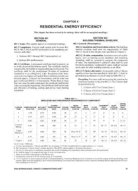
402.1.1 Insulation and fenestration criteria. The building<br />
thermal envelope shall meet the requirements of Table<br />
402.].J based on the elimate zone specified in Chapter 3.<br />
402.1.2 R-value computation. Insulation material used in<br />
layers, such as framing cavity insulation and insulating<br />
sheathing, shall be summed to compute the component<br />
R-value. The manufacturer's settled R-value shall bc used<br />
for blown insulation. Computed R-values shall not include<br />
an R-value for other building materials or air films.<br />
402.1.3 V-factor alternative. An assembly with aU-factor<br />
equal to or less than that specified in Table 402.] .3 shall be<br />
pcrmittedas an alternative to the R-value in Table402. I. I.<br />
Exception: For mass walls not meeting the criterion for<br />
insulation location in Section 402.2.3, the U-factor shall<br />
be permitted to be:<br />
1. U-factor of O. t7 in Climate Zone 1.<br />
2. U-factor of O. 14 in Climate Zone 2.<br />
3. U-faetor 01'0.12 in Climate Zone 3.<br />
TABLE 402.1.1<br />
INSULATION AND FENESTRATION REQUIREMENTS BY COMPONENT"<br />
CLIMATE<br />
ZONE<br />
FENESTRATION<br />
V·FACTOR<br />
SKYLIGHT"<br />
V-FACTOR<br />
GLAZED<br />
FENESTRATION<br />
SHGC<br />
CEILING<br />
R·VALUE<br />
WOOD<br />
FRAME WALL<br />
R·VALUE<br />
MASS<br />
BASEMENT"<br />
WALL FLOOR WALL<br />
R-VALUE R-VALUE R-VALUE<br />
SLAB"<br />
R-VALUE<br />
& DEPTH<br />
CRAWL<br />
SPACE c<br />
WALL<br />
R·VALUE<br />
1.20<br />
2 0.75<br />
3 0.65<br />
0.75 0.40 30 13 3 13 0<br />
0.75 0.40 30 13 4 13 0<br />
0.65 0.40' 30 13 5 19 0<br />
0 0<br />
0 0<br />
0 5/13<br />
4 except<br />
Marine<br />
0.40<br />
0.60 NR 38 13 5 19 10/ 13<br />
10, 2 ft J 0/ 13<br />
5 and<br />
Marine 4<br />
0.35<br />
0.60 NR 38 19 or 13+51! 13 30 t<br />
10/13<br />
10,2 ft 10/13<br />
6 0.35<br />
7 and 8 0.35<br />
0.60 NR 49 19 or 13+5[' 15 30' 10/13<br />
0.60 NR 49 21 19 30 t 10/ 13<br />
10,4 ft 10/13<br />
10,4 ft 10/13<br />
For 51: I Joot c.c 304.8 111111.<br />
,I. Rcvalu
RESIDENTIAL <strong>ENERGY</strong> EFFICIENCY<br />
TABLE 402.1.3<br />
EQUIVALENT U·FACTORS a<br />
CLIMATE<br />
ZONE<br />
FENESTRATION<br />
V-FACTOR<br />
SKYLIGHT<br />
V-FACTOR<br />
CEILING<br />
V-FACTOR<br />
FRAME<br />
WALL<br />
U·FACTOR<br />
MASS WALL<br />
V-FACTOR<br />
CRAWL<br />
BASEMENT SPACE<br />
FLOOR WALL WALL<br />
V-FACTOR V-FACTOR V-FACTOR<br />
1.2<br />
0.75 0.Q35<br />
0.082<br />
0.197<br />
0.064 0.360 0.477<br />
2 0.75<br />
0.75 0.035<br />
0.082<br />
0.165<br />
0.064 0.360 0.477<br />
3 0.65<br />
0.65 0.Q35<br />
0.082<br />
0.141<br />
O,(l47 0.360 0.136<br />
4 except Marine 0.40<br />
0.60 0.030<br />
0.082<br />
0.141<br />
0.047 0.059 0.065<br />
5 and Marine 4 0.35<br />
0.60 0.030<br />
0.060 0.082<br />
0.033 0.059 0.065<br />
6 0.35<br />
0.60 0.026<br />
0.060 0.06<br />
0.033 0.059 0.065<br />
7 and 8 0.35<br />
0.60 0.026<br />
0.057 0.057<br />
0.033 0,(J59 0.065<br />
a. Nonlcncxtrnrion U-[(j(·tors shall be obtained from measurement, calculation or an approved source.<br />
402.1.4 Total VA alternative. If the total building thermal<br />
envelope UA (sum of U-faetor times assembly area) is less<br />
than or equal to the total UA resulting from using the U-faetors<br />
in Table 402.1.3 (multiplied by the same assembly area<br />
as in the proposed building), the building shall be considered<br />
in compliance with Table 402.] .J. The UA calculation<br />
shall be done using a method consistent with the ASH RAE<br />
Handbook 0/ Fundamentals and shall include the thermal<br />
bridging effects of framing materials. The SHGC requirements<br />
shall be met in addition to UA compliance.<br />
402.2 Specific insulation requirements. (Prescriptive).<br />
20<br />
402.2.J Ceilings with attic spaces. When Section 402.1.1<br />
would require R-38 in the ceiling, R-30 shall be deemed to<br />
satisfy the requirement for R-38 wherever the full height of<br />
uncomprcsscd R-30 insulation extends over the wall top<br />
plate at the caves. Similarly R-38 shall be deemed to satisfy<br />
the requ iremcnt for R-49 wherever the full height ofuncornpressed<br />
R-38 insulation extends over the wall top plate at<br />
the eaves.<br />
402.2.2 Ceilings without attic spaces. Where Section<br />
402.1.1 would require insulation levels above R-30 and the<br />
design ofthe roo f/ceiling assembly docs not allow sufficient<br />
space for the required insulation, the minimum required<br />
insulation for such roof/ceiling assemblies shall be R-30.<br />
This reduction of insulation from the requirements of Section<br />
402.1.] shall be limited to 500 square feet (46 m 2 ) of<br />
ceiling area.<br />
402.2.3 Mass walls. Mass walls for the purposes of this<br />
Chapter shall be considered walls of concrete block, concrete,<br />
insulated concrete form (ICF), masonry cavity, brick<br />
(other than brick veneer), earth (adobe, compressed earth<br />
block, rammed earth) and solid timber/logs. The provisions<br />
of Section 402. 1.1 for mass walls shall be applicable when<br />
at least 50 percent of the required insulation R-value is on<br />
the exterior of, or integral to. the wall. Walls that do not meet<br />
this criterion for insulation placement shall meet the wood<br />
frame wall insulation requirements of Section 402.1.1.<br />
Exception: For walls that do not meet the criterion for<br />
insulation placement, the minimum added insulation<br />
R-value shall be permitted to be:<br />
I. R-value of 4 in Climate Zone I.<br />
2. R-value of 6 in Climate Zone 2.<br />
3. R-value of 8 in Climate Zone 3.<br />
402.2.4 Steel-frame ceilings, walls and floors. Steelframe<br />
ceilings, walls and floors shall meet the insulation<br />
requirements of Table 402.2.4 or shall meet the U-factor<br />
requirements in Table 402.1.3. The calculation ofthe U-factor<br />
for a steel-frame envelope assembly shall usc a<br />
series-parallel path calculation method.<br />
TABLE 402.2,4<br />
STEEL-FRAME CEILING, WALL AND FLOOR INSULATION<br />
(R-VALUE)<br />
r<br />
i WOOD FRAME<br />
i R-VALUE i COLD·FORMED STEEL<br />
I_BEQUIi!E:IVIENT L EQUIVALENT R-VALUE"<br />
Steel Truss _(;eilings b<br />
i<br />
R-30 R - 38 or R - 30 -I-3 or R - 26 -I- 5<br />
-.--- -- ---<br />
I<br />
R-38 R - 49 or R - 38 -I- }<br />
I<br />
! RA9 R-38+5<br />
i<br />
Steel,J()ist Ceiling!;"<br />
I<br />
R - 38 in 2x4 or 2x6 or 2x8<br />
R-30<br />
__ 8 - 49ilLany framing<br />
I<br />
R-38 R - 49 in 2x4 or 2x6 or2x8 or 2x 10<br />
1 Steel Framed Wall<br />
I<br />
R-13 R - I 3 + 5 or R - 15 -I- 4 or R - 21 -I-3<br />
i"-<br />
R-I9 R - 13 -I-9 or R - 19-l- 8 or R - 25 +<br />
i'<br />
R-21 R - 13 -I- 10 or R - 19 -I- 9 or R - 25 -l- 8<br />
I<br />
I<br />
Steel Joist Floor<br />
I<br />
i<br />
R - 19 in 2x6<br />
R-13<br />
I- ReI 9_+ 6 inZX8 or 2 >
RESIDENTIAL <strong>ENERGY</strong> EFFICIENCY<br />
402.2.5 Floors. Floor insulation shall be installed to maintain<br />
permanent contact with the underside of the subfloor<br />
decking.<br />
402.2.6 Basement walls. Walls associated with conditioned<br />
basements shall be insulated from the top of the basement<br />
wall down to J0 feet (3048 mrn) below grade or to the basement<br />
floor, whichever is less. Walls associated with unconditioned<br />
basements shall meet this requirement unless the<br />
floor overhead is insulated in accordance with Sections<br />
402.1.1 and 402.2.5.<br />
402.2.7 Slab-on-grade floors. Slab-on-grade floors with a<br />
floor surface less than 12 inches (305 mm) below grade shall<br />
be insulated in accordance with Table 402.1.1. The insulation<br />
shall extend downward from the top ofthe slab on the outside<br />
or inside of the foundation wall. Insulation located below<br />
grade shall be extended the distance provided in Table<br />
402.1.1 by any combination ofvertical insulation, insulation<br />
extending under the slab or insulation extending out from the<br />
building. Insulation extending away from the building shall<br />
be protected by pavement or by a minimum of I0 inches (254<br />
111m) ofsoil. The top edge ofthe insulation installed between<br />
the exterior wall and the edge ofthe interior slab shall be permitted<br />
to be cut at a 45-degree (0.79 rad) angle away from the<br />
exterior wall. Slab-edge insulation is not required in jurisdictions<br />
designated by the code official as having a very heavy<br />
termite infestation.<br />
402.2.8 Crawl space walls. As an alternative to insulating<br />
floors over crawl spaces, crawl space walls shall be permitted<br />
to be insulated when the crawl space is not vented to the<br />
outside. Crawl space wall insulation shall be permanently<br />
fastened to the wall and extend downward from the floor to<br />
the finished grade level and then vertically and/or horizontally<br />
for at least an additional 24 inches (610 mm). Exposed<br />
earth in unvented crawl space foundations shall be covered<br />
with a continuous vapor retarder. All joints of the vapor<br />
retarder shall overlap by 6 inches (153 mm) and be scaled or<br />
taped. The edges ofthe vapor retarder shall extend at least 6<br />
inches (153 mm) up the stem wall and shall be attached to<br />
the stem wall.<br />
402.2.9 Masonry veneer. Insulation shall not be required<br />
on the horizontal portion of the foundation that supports a<br />
masonry veneer.<br />
402.2.10 Thermally isolated sunroom insulation. The<br />
minimum ceiling insulation R-values shall be R-19 in zones<br />
I through 4 and R-24 in zones 5 though 8. The minimum<br />
wall R-value shall be R-13 in all zones. New wall(s) separating<br />
a sunroom from conditioned space shall meet the building<br />
thermal envelope requirements.<br />
402.3 Fenestration. (Prescriptive).<br />
402.3.1 V-factor. An area-weighted average offenestration<br />
products shall be permitted to satisfy the V-factor requirements.<br />
402.3.2 Glazed fenestration SHGC. An area-weighted<br />
average of fenestration products more than SO percent<br />
glazed shall be permittedto satisfy the SHGe requirements.<br />
<strong>2006</strong> <strong>INTERNATIONAL</strong> <strong>ENERGY</strong> <strong>CONSERVATION</strong> <strong>CODE</strong>@<br />
402.3.3 Glazed fenestration exemption. Up to IS square<br />
feet (1.4 m 2 ) ofglazed fenestration per dwell ing unit shall be<br />
permitted to be exempt from [f.·factor and SHGC requirements<br />
in Section 402.1.1.<br />
402.3.4 Opaque door exemption. One opaque door assembly<br />
is exempted from the U-faetor requirement in Section<br />
402.1.1.<br />
402.3.5 Thermally isolated sunroom V-factor. For Zones<br />
4 through 8, the maximum fenestration V-factor shall be<br />
0.50 and the maximum skylight U-faetor shall be 0.75. New<br />
windows and doors separating the sunroom from conditioned<br />
space shall meet the building thermal envelope<br />
requirements.<br />
402.3.6 Replacement fenestration. Where some or all of<br />
an existing fenestration unit is replaced with a new fenestration<br />
product, including sash and glazing, the replacement<br />
fenestration unit shall meet the applicable requirements for<br />
V-factor and SHOC in Table 402.1. I.<br />
402.4 Air leakage. (Mandatory).<br />
402.4.1 Building thermal envelope. The building thermal<br />
envelope shall be durably sealed to limit infiltration. The<br />
scaling methods between dissimilar materials shall allow for<br />
differential expansion and contraction. The following shall<br />
be caulked, gasketed, weathcrstrippcd or otherwise scaled<br />
with an air barrier material, suitable film or solid material:<br />
I. All joints, seams and penetrations.<br />
2. Site-built windows, doors and skylights.<br />
3. Openings between window and door assemblies and<br />
their respective jambs and framing.<br />
4. Utility penetrations.<br />
5. Dropped ceilings or chases adjacent to the thermal<br />
envelope.<br />
6. Knee walls.<br />
7. Walls lind ceilings separating a garage from conditioned<br />
spaces.<br />
8. Behind tubs and showers on exterior walls.<br />
9. Common walls between dwelling units.<br />
10. Other sources of infiltration.<br />
402.4.2 Fenestration air leakage. Windows, skylights and<br />
sliding glass doors shall have an air infiltration rate of no<br />
more than 0.3 din per square foot (1.5 Lls/m\ and swinping<br />
doors no more than 0.5 cfrn per square foot (2.6 Lzs/rn"),<br />
when tested according to NFRC 400 or AAMA/WDMA/<br />
CSA 10l/J.S.2/A440 by an accredited, independent laboratory<br />
and listed and labeled by the manufacturer.<br />
Exceptions: Site-built windows, skylights and doors.<br />
402.4.3 Recessed lighting. Recessed luminaires installed in<br />
the building thermal envelope shall be sealed to limit air<br />
leakage between conditioned and unconditioned spaces by<br />
being:<br />
I. rC-rated and labeled with enclosures that are sealed or<br />
gasketed to prevent air leakage to the cei ling cavity or<br />
unconditioned space; or<br />
21
RESiDENTiAL <strong>ENERGY</strong> EFFICIENCY<br />
2. IC-rated and labeled as meeting ASTM E 283 when<br />
tested atl.57 psi (75 Pa) pressure differential with no<br />
more than 2.0 cfm (0.944 Lis) of air movement from<br />
the conditioned space to the ceiling cavity; or<br />
3. Located inside an airtight sealed box with clearances<br />
of at least 0.5 inch (12.7 mm) from combustible material<br />
and 3 inches (76 mm) from insulation.<br />
402.5 Moisture control. (Mandatory). The building design<br />
shall not create conditions of accelerated deterioration from<br />
moisture condensation, Above-grade frame walls, floors and<br />
ceilings not ventilated to allow moisture to escape shall be provided<br />
with an approved vapor retarder, The vapor retarder shall<br />
be install cd on the warm-in-winter side of the thermal insulation.<br />
Exceptions:<br />
I. In construction where moisture or its freezing will not<br />
damage the materials.<br />
2. Frame walls, floors and ceilings in jurisdictions in<br />
Zones 1 through 4. (Crawl space floor vapor retarders<br />
are not exempted.)<br />
3. Where other approved means to avoid condensation<br />
are provided.<br />
402.6 Maximum fenestration V-factor and SHGC. (Mandatory).<br />
The area weighted average maximum fenestration<br />
V-factor permitted using trade offs from Section 402.104 or<br />
Section 404 shall be 0048 in zones 4 and 5 and 0040 in zones 6<br />
through 8 for vertical fenestration, and 0.75 in zones 4 through<br />
8 for skyl ights. The area weighted average maximum fenestration<br />
SHGC permitted using trade-offs from Section 404 in<br />
Zoncs I through 3 shall be 0.50.<br />
SECTION 403<br />
SYSTEMS (Mandatory)<br />
403.1 Controls. At least one thermostat shall be provided for<br />
cach separate heating and cooling system.<br />
403.1.1 Heat pump supplementary heat. Heat pumps<br />
having supplementary electric-resistance heat shall have<br />
controls that, except during defrost, prevent supplemental<br />
heat operation when the heat pump compressor can meet the<br />
heating load.<br />
403.2 Ducts.<br />
22<br />
403.2.1 Insulation. Supply and retUI11 ducts shal1 be insulatcd<br />
to a minimum of R-8. Ducts in floor trusses shall be<br />
insulated to a minimum of R-6.<br />
Exception: Ducts or portions thereoflocated completely<br />
inside the building thermal envelope.<br />
403.2.2 Sealing. All ducts, air handlers, filter boxes, and<br />
building cavities used as ducts shall be sealed. Joints and<br />
seams sha IIcomply with Section M 160 1.3.1 ofthe International<br />
Residential Code.<br />
403.2.3 Building cavities. Building framing cavities shall<br />
not be used as supply ducts.<br />
403.3 Mechanical system piping insulation. Mechanical system<br />
piping capable of carrying fluids above 105°F (41°C) or<br />
below 55°F (13°C) shall be insulated to a minimum of R-2.<br />
403.4 Circulating hot water systems. All circulating service<br />
hot water piping shall be insulated to at least R-2. Circulating<br />
hot water systems shall include an automatic or readily accessible<br />
manual switch that can turn off the hot water circulating<br />
pump when the system is not in use.<br />
403.5 Mechanical ventilation. Outdoor air intakes and<br />
exhausts shall have automatic or gravity dampers that close<br />
when the ventilation system is not operating.<br />
403.6 Equipment sizing. Heating and cooling equipment shall<br />
be sized in accordance with Section M 140 1.3 of the International<br />
Residential Code.<br />
SECTION 404<br />
SIMULATED PERFORMANCE ALTERNATIVE<br />
(Performance)<br />
404.1 Scope. This section establishes criteria for compliance<br />
using simulated energy performance analysis. Such analysis<br />
shall include heating, cooling, and service water heating<br />
energy only.<br />
404.2 Mandatory requirements. Compliance with this Section<br />
requires that the eritcria of Sections 40 I, 40204, 402.5,<br />
402.6 and 403 be met.<br />
404.3 Performance-based compliance. Compliance based on<br />
simulated energy performance requires that a proposed residence<br />
(proposed design) be shown to have an annual energy<br />
cost that is less than or equal to the annual energy cost of the<br />
standard reference design. Energy prices shall be taken from a<br />
source approved by the code official, such as the Department of<br />
Energy, Energy Information Administration's State Energy<br />
Price and Expenditure Report. Code officials shall be permitted<br />
to require time-of-usc pricing in energy cost calculations.<br />
Exception: Jurisdictions that require site energy (Lk Wh =<br />
3,413 Btu) rather than energy cost as the metric ofcomparison.<br />
404.4 Documentation.<br />
404.4.1 Compliance software tools. Documentation verifying<br />
that the methods and accuracy ofthc compliance software<br />
tools conform to the provisions ofthis section shall be<br />
provided to the code official.<br />
404.4.2 Compliance report. Compliance software tools<br />
shall generate a report that documents that the proposed<br />
design has annual energy costs less than or equal to the<br />
annual cnergy costs of the standard reference design. The<br />
compliance documentation shall include the following<br />
information:<br />
1. Address of the residence:<br />
2. An inspection checklist documenting the building<br />
component characteristics or the proposed design as<br />
listed in Table 404.5.2( I). The inspection checklist<br />
shall show the estimated annual energy cost for both<br />
<strong>2006</strong> <strong>INTERNATIONAL</strong> <strong>ENERGY</strong> <strong>CONSERVATION</strong> <strong>CODE</strong>@
RESIDENTIAL <strong>ENERGY</strong> EFFICIENCY<br />
the standard reference design and the proposed<br />
design:<br />
3. Name of individual completing the compliance<br />
report; and<br />
4. Name and version of the compliance soft ware tool.<br />
official shall be permitted to approve tools for a specified<br />
application or limited scope.<br />
404.6.3 Input values. When calculations require input values<br />
not specified by Sections 402, 403 and 404, those input<br />
values shall be taken from an approved source.<br />
404.4.3 Additional documentation. The code official shall<br />
bc permitted to require the following documents:<br />
I. Documentation of the building component characteristics<br />
of the standard reference design.<br />
2. A certification signed by the builder providing the<br />
building component characteristics of the proposed<br />
design as given in Table 404.5.20).<br />
404.5 Calculation procedure.<br />
404.5.1 General. Except as specified by this section, the<br />
standard reference design and proposed design shall be configured<br />
and analyzed using identical methods and techniques.<br />
404.5.2 Residence specifications. The standard reference<br />
design and proposed design shall be configured and analyzed<br />
as specified by Table 404.5.2( I). Table 404.5.2(1)<br />
shall include by reference all notes contained in Table<br />
402.1.1.<br />
404.6 Calculation software tools.<br />
404.6.1 Minimum capabilities. Calculation procedures<br />
used to comply with this section shall be software tools<br />
capable ofcalculating the annual energy consumption ofall<br />
building clements that differ between the standard reference<br />
design and the proposed design and shall include the following<br />
eapabiJ ities:<br />
I. Computer generation of the standard reference design<br />
using only the input for the proposed design. The calculation<br />
procedure shall not allow the user to directly<br />
modify the building component characteristics of the<br />
standard reference design.<br />
2. Calculation ofwhole-building (as a single zone) sizing<br />
for the heating and cooling equipment in the standard<br />
reference design residence in accordance with Section<br />
M 1401.3 of the International Residential Code.<br />
3. Calculations that account for the effects of indoor and<br />
outdoor temperatures and part-load ratios on the performance<br />
of heating, ventilating and air conditioning<br />
equipment based on climate and equipment sizing.<br />
4. Printed code official inspection checklist listing each<br />
of the proposed design component characteristics<br />
from Table 404.5.2(1) determined by the analysis to<br />
provide compliance, along with their respective performance<br />
ratings (e.g. R- Value, V-Factor, SHGC,<br />
HSPF, AFTJE, SEER, EF, etc.),<br />
404.6.2 Specific approval. Performance analysis tools<br />
meeting the applicable sections of404 shall be permitted to<br />
be approved. Tools are permitted to be approved based on<br />
meeting a specified threshold for a jurisdiction. The code<br />
<strong>2006</strong> <strong>INTERNATIONAL</strong> <strong>ENERGY</strong> <strong>CONSERVATION</strong> <strong>CODE</strong>®<br />
23
RESIDENTIAL <strong>ENERGY</strong> EFFICIENCY<br />
TABLE 404.5.2(1)<br />
SPECIFICATIONS FOR THE STANDARD REFERENCE AND PROPOSED DESIGNS<br />
BUILDING COMPONENT<br />
Above-grade walls<br />
Basement and crawlspace<br />
walls<br />
Above-grade floors<br />
Ceilings<br />
Roofs<br />
Attics<br />
Foundations<br />
Doors<br />
Glazing"<br />
Skylights<br />
Thermally isolated<br />
sunroorns<br />
STANDARD REFERENCE DESIGN<br />
Type: mass wall if proposed wall is mass: otherwise<br />
wood frame<br />
Gross area: same as proposed<br />
U-Factor: from Table 402.1.3<br />
Solar absorptance = 0.75<br />
Emittance = 0.90<br />
_ _~--- ---~---_ ~- .._-~---<br />
Type: same as proposed<br />
Gross area: same as proposed<br />
U-Factor: from Table 402.1.3 with insulation layer<br />
on interior side of walls<br />
Type: wood frame<br />
Gross area: same as proposed<br />
V-Factor: from Table 402.1.3<br />
Type: wood frame<br />
Gross area: same as proposed<br />
V-Factor: from Table 402.].3<br />
Type: composition shingle on wood sheathing<br />
Gross area: same as proposed<br />
Solar absorptance ~~ 0.75<br />
Emittance ~ 0.90<br />
Type: vented with aperture = 1 tt 2 per 300 ft 2 ceiling<br />
area<br />
Type: same as proposed<br />
----- ._.-.__.._-------_. --._---.-----<br />
Area: 40 ft 2<br />
Orientation: North<br />
U-factor: same as fenestration from Table 402.1.3<br />
Total area" =<br />
The proposed glazing area; where the proposed<br />
glazing area is less than 18'Yc, of the conditioned<br />
floor area<br />
18% of the conditioned floor area; where the<br />
proposed glazing area is 18'% or more of the<br />
conditioned floor area<br />
Orientation: equally distributed to four cardinal<br />
compass orientations (N. E. S, & W)<br />
LJ-factor: from Table 402.1.2<br />
SHGC: From Table 402.1 except that for climates with<br />
no requirement (NR) SHGC = 0040 shall be used<br />
Interior shade fraction:<br />
Summer (all hours when cooling is required) = 0.70<br />
Winter (all hours when heating is required) '- 0.85<br />
External shading: none<br />
-------- .. _-,,-<br />
None<br />
None<br />
(coil/inlied)<br />
PROPOSED DESIGN<br />
As proposed<br />
As proposed<br />
As proposed<br />
As proposed<br />
A,:]J~()pose_cl_<br />
As proposed<br />
As proposed<br />
As proposed<br />
As proposed<br />
As proposed<br />
As proposed<br />
_.._---- - .-- ----_....<br />
As proposed<br />
As proposed<br />
As proposed<br />
As proposed<br />
As proposed<br />
As proposed<br />
As proposed<br />
As proposed<br />
As proposed<br />
As proposed<br />
As proposed<br />
As proposed<br />
As proposed<br />
As proposed<br />
As proposed<br />
As proposed<br />
Same as standard reference design"<br />
As proposed<br />
As proposed<br />
As proposed<br />
24<br />
<strong>2006</strong> <strong>INTERNATIONAL</strong> <strong>ENERGY</strong> <strong>CONSERVATION</strong> <strong>CODE</strong>~
RESIDENTIAL <strong>ENERGY</strong> EFFICIENCY<br />
TABLE 404.5.2(1)<br />
SPECIFICATIONS FOR THE STANDARD REFERENCE AND PROPOSED DESIGNS-continued<br />
BUILDING COMPONENT<br />
STANDARD REFERENCE DESIGN<br />
PROPOSED DESIGN<br />
Air exchange rate<br />
Mechanical ventilation<br />
Internal gains<br />
Specific Leakage Area (SLAyl = 0.00036 assuming no For residences that are not tested, the same as the<br />
energy recovery<br />
standard reference design<br />
For residences without mechanical ventilation that arc<br />
tested in accordance with ASHRAE 119, Section 5. I,<br />
the measured air exchange rate" but not less than 0.35<br />
ACH<br />
For residences with mechanical ventilation that arc tested<br />
in accordance with ASH RAE I J9, Section 5.1, the<br />
measured air exchange rate" combined with the<br />
mechanical ventilation rate. f which shall not be less<br />
than OJ)] x CFA + 7.5 x (Nf,,+I)<br />
where:<br />
CFA = conditioned floor area<br />
N"r = number of bedrooms<br />
- ----------- - ----- -------------,-----------------<br />
None, except where mechanical ventilation is specified<br />
by the proposed design, in which case:<br />
Annual vent fan energy usc: kWh/yr = 0.03942 x CF4<br />
+ 29.565 x (N,,,'+ 1)<br />
where:<br />
eFA = conditioned floor area<br />
N;,,- = number of bedrooms<br />
IGain -~-17,900 + 23.8 x efA +4J04 X Ni;<br />
(Btu/day per dwelling unit)<br />
As proposed<br />
Same as standard reference design<br />
Intcrnal mass<br />
Structural mass<br />
Heating systems" j<br />
Cooling systems" i<br />
An internal mass for furniture and contents of 8<br />
pounds per square foot of floor area<br />
For masonry floor slabs, 80% of floor area covered by<br />
R-2 carpet and pad, and 20'% of floor directly<br />
exposed to room air<br />
For masonry basement walls, as proposed, but with<br />
insulation required by Table 402.1.3 located on the<br />
interior side of the walls<br />
For other walls, for ceilings, floors, and interior walls,<br />
wood frame construction<br />
Fuel type: same as proposed design<br />
Efficiencies:<br />
Electric: air-source heat pump with prevailing<br />
federal minimum efficiency<br />
Nonelectric furnaces: natural gas furnace with<br />
prevailing federal minimum efficiency<br />
Nonelectric boilers: natural gas boiler with<br />
prevailing federal minimum efficiency<br />
Capacity: sized in accordance with Section<br />
M 140 1.3 of the International Residential Code<br />
Fuel type: Electric<br />
Efficiency: in accordance with prevailing federal<br />
minimum standards<br />
Capacity: sized in accordance with Section M 1401.3<br />
of the lnternational Residential Code<br />
(continued)<br />
Same as standard reference design, plus any additional<br />
mass specifically designed as a thermal storage<br />
clement" but not integral to the building envelope or<br />
structure<br />
As proposed<br />
As proposed<br />
As proposed<br />
As proposed<br />
As proposed<br />
As proposed<br />
As proposed<br />
As proposed<br />
As proposed<br />
As proposed<br />
As proposed<br />
<strong>2006</strong> <strong>INTERNATIONAL</strong> <strong>ENERGY</strong> <strong>CONSERVATION</strong> <strong>CODE</strong> '0 25
RESIDENTIAL <strong>ENERGY</strong> EFFICIENCY<br />
TABLE 404.5.2(1)<br />
SPECIFICATIONS FOR THE STANDARD REFERENCE AND PROPOSED DESIGNS-continued<br />
Fuel type: same as proposed design<br />
Efficiency: in accordance with prevailing Federal<br />
minimum standards<br />
Use: gal/day c_ 30 + lOx tVl"<br />
Tank temperature: 1200F<br />
As proposed<br />
As proposed<br />
Same as standard reference<br />
Same as standard reference<br />
A thermal distribution system efficiency (DS!::) of 0.80 Same as standard reference design. except as<br />
shall be applied to both the heating and cooling system specified by Table 404.5.2(2)<br />
efficiencies<br />
Type: manual, cooling temperature set point > nOF; Same as standard reference design<br />
heating temperature set point = 68°F<br />
.... ------- ------ ~ --._-,,------ ..•._---_._<br />
For SI: I square foot = 0.93 m'; I British thermal unit = 1055 J; I pound per square foot = 4.88 kg/m 2 ; I gallon (U.S.) = 3.n5 L; °C c~ eF-32)/1.8.<br />
a. Glazing shall be defined as sunlight-transmitting fenestration, including the area ofsash, curbing or other framing clements, that enclose conditioned space. Glazing<br />
includes the area ofsunlight-transmitting fenestration assemblies in walls bounding conditioned basements. For doors where the sunlight-transmitting opening<br />
is less than 50%, ofthe door area. the glazing area is the sunlight rransmirringopening area. For all other doors. the glazing area is the rough frame opening area<br />
tor the door including the door and the frame.<br />
b. For residences wilh conditioned basements, R-2 and R-4 residences and townhouses, the followiug formula shall be used to determine gla:ring area:<br />
AI-' A, xF4 x I-'<br />
where:<br />
AF Tolal glazing area.<br />
A, Standard reference design total glazing area.<br />
f",j (Above-grade thermal boundary gross wall urca j/rabovc-gradc boundary wall area + 0.5 x below-grade boundary wall area).<br />
F (Above-grade thermal boundary wall areal/labove-grade thermal boundary wall area + common wall area) or 0.56, whichever is greater.<br />
;ll1d where:<br />
Thermal boundary wall is any wall that separates conditioned space hom unconditioned space or ambient conditions.<br />
Above-grade thermal boundary wall is any thermal boundary wall component not in contact with soil.<br />
Below-grade boundary wall is any thermal boundary wall in soil contact.<br />
Common wall area is the area of walls shared with an adjoining dwelling unit.<br />
c. For fenestrations facing within 15 degrees (0.26 rad) oftrue south that are directly coupled to thermal storage mass, the winter interior shade traction shall be permitted<br />
to be increased to 0.95 in the proposed design.<br />
d. Where Leakage Area (I,) is defined in accordance with Section 5.1 ofASIIRAE 119 and where:<br />
SLA =!.ICI-'A<br />
where I, and CF4 are in the same units.<br />
e. Tested envelope leakage shall be determined and documented by an independent party approved by the code official. IIourly calculations as specified in the 200 I<br />
ASHRAF l landbook ofFundamentals, Chapter 26. page 26.21, Equation 40 (Shcnnan-Grirnsrud model) or the equivalent shall be used to determine the energy<br />
loads resulting from infiltration.<br />
f The combined air exchange rate for infiltration and mechanical ventilation shall be determined in accordance with Equation 43 of200J ASIIRAE Handbook of<br />
Fundamentals page 26.24 and the "Whole-house Ventilation" provisions of200 I ASHRAE Handbook ofFundamentals, page 26.19 (or intermittent mechanical<br />
vcnulation.<br />
g. Thermal Storage Element shall mean a component not part ofthe floors. walls or ceilings that is part ofa passive solar system, and that provides thermal storage<br />
such as enclosed water columns, rock beds. or phase-change containers. A thermal storage element must be in the same room as (cnestration that (aces within 15<br />
degrees (0.26 rad) of true south, or must be connected to such a room with pipes or ducts that allow the element to be actively charged.<br />
h. For a proposed design with multiple heating, cooling or water heating systems using different fuel types, the applicable standard reference design system capacilies<br />
and fuel types shall be weighted in accordance with their respective loads as calculated by accepted engineering practice for each equipment and fuel type<br />
present.<br />
i. For a proposed design without a proposed heating system. a heating system with the prevailing federal minimum efficiency shall be assumed 1'01'both the standard<br />
reference design and proposed design. For electric heating systems, the prevailing federal minimum efficiency air-source heat pump shall be used till'the standard<br />
reference ttcsign,<br />
j. For a proposed design home without a proposed cooling system. an electric air conditioner with the prevailing federal minimum efficiency shall be assumed (or<br />
both the standard reference design and the proposed design.<br />
k. For a proposed design with a nonstoragc-rype water heater, a 40-gallon storage-type water heater with the prevailing federal minimum Energy Factor for the sam"<br />
[ucl as the predominant heating fuel type shall be assumed. For the case of a proposed design without a proposed water heater, a 40-gallon storage-type water<br />
heater with the prevailing Icderal minimum efficiency 1'01'the same fuel as the predominant heating fuel type shall be assumed lor both the proposed design and<br />
standard reference design.<br />
26<br />
<strong>2006</strong> <strong>INTERNATIONAL</strong> <strong>ENERGY</strong> <strong>CONSERVATION</strong> <strong>CODE</strong>®
RESIDENTIAL <strong>ENERGY</strong> EFFICIENCY<br />
TABLE 404.5.2(2)<br />
DEFAULT DISTRIBUTION SYSTEM EFFICIENCIES FOR PROPOSED DESIGNS"<br />
DISTRIBUTION SYSTEM CONI:IGURATION AND CONDITION:<br />
- .. -<br />
FORCED AIR<br />
SYSTEMS<br />
HYDRONIC<br />
SYSTEMS b<br />
Distribution system eomp()I]I~ll.tsJ()cated_~n UIJ.C:()Tlclitiol1~cl..s.pace 0.80 0.95<br />
Distribution sy's~elTlsc;Il!ir_ely'l 0Y~£Cc1.il](;c.)n_d}!i.0llecl_s'p'[l_c.ec_ (U8 1.00<br />
Proposed "reduced leakage" with entire air distribution system located in the conditioned 0.96<br />
spaced<br />
Proposed "reduced leakage" air distribution system with components located in the 0.88<br />
unconditionecl.;'pace<br />
i "Ductless" systems" 1.00<br />
For Sl: j cubic foot per minute ~. 0.47 Lis: 1 square foot = 0.093 m 2 ; 1 pound per square inch = 6895 Pa; I inch water gauge = 1250 Pa,<br />
a. Default values given by this table are for untested distribution systems, which must still meet minimum requirements for duct system insulation.<br />
b. Hydronic Syslems shall mean those systems that distribute heating and cooling energy directly to individual spaces using liquids pumped through closed loop piping<br />
and that do not depend OJ) ducied, forced air flows to maintain space temperatures.<br />
c. Entire system in conditioned space shall mean that no component of the distribution system, including the air handler unit, is located outside of the conditioned<br />
space.<br />
d. Proposed "reduced leakage" shall mean leakage to outdoors not grearerrhan 3 cfrn per 100 ti 2 of conditioned l100r area and total leakage not greater than 9 cfrn per<br />
100 et'ofconditioned floor area at a pressure differential 01'0.02 inches w.g. (25 Pal across the entire system, including the manufacturer's air handler enclosure.<br />
Total leakage ofnot greater than 3 cfrn per 100 It' ofconditioned floor area at a pressure difference 01'0.02 inches w.g. (25 PaJ across the entire system, including<br />
the manufacturer's air handlerenclosure, shall be deemed to meet this requirement withour rncasuremcnt ofleakagc to outdoors. This performance shall be specified<br />
as required in the construction documents and confirmed through field-testing of installed systems as documented by an approved independent party.<br />
c. Ductless systems may have forced airflow across a coil but shall not have any dueled airflows external to the manufacturer's air handler enclosure.<br />
<strong>2006</strong> <strong>INTERNATIONAL</strong> <strong>ENERGY</strong> <strong>CONSERVATION</strong> <strong>CODE</strong>"" 27