You also want an ePaper? Increase the reach of your titles
YUMPU automatically turns print PDFs into web optimized ePapers that Google loves.
M-00-41<br />
REV D<br />
AUGUST 2012<br />
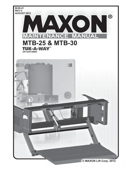
MAINTENANCE MANUAL<br />
<strong>MTB</strong>-<strong>25</strong> & <strong>MTB</strong>-<strong>30</strong><br />
© MAXON Lift Corp. 2012
LIFT CORP.<br />
11921 Slauson Ave.<br />
Santa Fe Springs, CA. 90670<br />
CUSTOMER SERVICE:<br />
TELEPHONE (562) 464-0099 TOLL FREE (800) 227-4116<br />
FAX: (888) 771-7713<br />
NOTE: For latest version of all Manuals (and replacements), download the<br />
Manuals from <strong>Maxon</strong>’s website at www.maxonlift.com.<br />
WARRANTY/ RMA POLICY & PROCEDURE<br />
LIFTGATE WARRANTY<br />
Type of Warranty:<br />
Term of Warranty:<br />
Full Parts and Labor<br />
Standard Liftgates - 2 years from ship date or 6,000 cycles<br />
Premium Liftgates - 2 years from ship date or 10,000 cycles<br />
This warranty shall not apply unless the product is installed, operated and maintained in accordance with MAXON Lift’s specifi cations as set forth in<br />
MAXON Lift’s Installation, Operation and Maintenance manuals. This warranty does not cover normal wear, maintenance or adjustments, damage or<br />
malfunction caused by improper handling, installation, abuse, misuse, negligence, or carelessness of operation. In addition, this warranty does not<br />
cover equipment that has had unauthorized modifi cations or alterations made to the product.<br />
MAXON agrees to replace any components which are found to be defective during the fi rst 2 years of service, and will reimburse for labor based on<br />
MAXON’s Liftgate Warranty Flat Rate Schedule. (Copy of the Flat Rate is available at www.maxonlift.com.)<br />
All warranty repairs must be performed by an authorized MAXON warranty facility. For any repairs that may exceed $500, including parts and labor,<br />
MAXON’s Technical Service Department must be notifi ed and an “Authorization Number” obtained.<br />
All claims for warranty must be received within <strong>30</strong> Days of the repair date, and include the following information:<br />
1. Liftgate Model Number and Serial Number<br />
2. The End User must be referenced on the claim<br />
3. Detailed Description of Problem<br />
4. Corrective Action Taken, and Date of Repair<br />
5. Parts used for Repair, Including MAXON Part Number(s)<br />
6. MAXON R.M.A. # and/or Authorization # if applicable (see below)<br />
7. Person contacted at MAXON if applicable<br />
8. Claim must show detailed information i.e. Labor rate and hours of work performed<br />
Warranty claims can also be placed online at www.maxonlift.com. Online claims will be given priority processing.<br />
All claims for warranty will be denied if paperwork has not been received or claim submitted via <strong>Maxon</strong> website for processing by MAXON’s Warranty<br />
Department within <strong>30</strong> days of repair date.<br />
All components may be subject to return for inspection, prior to the claim being processed. MAXON products may not be returned without prior written<br />
approval from MAXON’s Technical Service Department. Returns must be accompanied by a copy of the original invoice or reference with original<br />
invoice number and are subject to a credit deduction to cover handling charges and any necessary reconditioning costs. Unauthorized returns will be<br />
refused and will become the responsibility of the returnee.<br />
Any goods being returned to MAXON Lift must be pre-approved for return, and have the R.M.A. number written on the outside of the package in plain<br />
view, and returned freight prepaid. All returns are subject to a 15% handling charge if not accompanied by a detailed packing list. Returned parts<br />
are subject to no credit and returned back to the customer. Defective parts requested for return must be returned within <strong>30</strong> days of the claim date for<br />
consideration to:<br />
MAXON Lift Corp.<br />
10321 Greenleaf Ave., Santa Fe Springs, CA 90670<br />
Attn: RMA#__<br />
MAXON’s warranty policy does not include the reimbursement for travel time, towing, vehicle rental, service calls, oil, batteries or loss of income due to<br />
downtime. Fabrication or use of non <strong>Maxon</strong> parts, which are available from MAXON, are also not covered.<br />
MAXON’s Flat Rate Labor Schedule takes into consideration the time required for diagnosis of a problem.<br />
All Liftgates returned are subject to inspection and a 15% restocking fee. Any returned Liftgates or components that have been installed or not returned<br />
in new condition will be subject to an additional reworking charge, which will be based upon the labor and material cost required to return the Liftgate or<br />
component to new condition.<br />
PURCHASE PART WARRANTY<br />
Term of Warranty: 1 Year from Date of Purchase.<br />
Type of Warranty: Part replacement only. MAXON will guarantee all returned genuine MAXON replacement parts upon receipt and inspection of parts<br />
and original invoice.<br />
All warranty replacements parts will be sent out via ground freight. If a rush shipment is requested, all freight charges will be billed to the requesting<br />
party.
TABLE OF CONTENTS<br />
WARNINGS ........................................................................................................................... 6<br />
LIFTGATE TERMINOLOGY <strong>MTB</strong>-<strong>25</strong> & <strong>MTB</strong>-<strong>30</strong> ................................................................... 8<br />
PERIODIC MAINTENANCE ................................................................................................ 10<br />
PERIODIC MAINTENANCE CHECKS ................................................................................ 10<br />
PERIODIC MAINTENANCE CHECKLIST ............................................................................11<br />
CHECKING HYDRAULIC FLUID ........................................................................................ 12<br />
CHANGING HYDRAULIC FLUID ........................................................................................ 14<br />
PLATFORM ADJUSTMENT ................................................................................................ 16<br />
REPLACING PLATFORM TORSION SPRING ................................................................... 18<br />
SAFETY HOOK MAINTENANCE ....................................................................................... 20<br />
PARTS BREAKDOWN ....................................................................................................... 21<br />
<strong>MTB</strong>-<strong>25</strong> & <strong>MTB</strong>-<strong>30</strong> MAIN ASSEMBLY ................................................................................. 21<br />
MAIN FRAME ASSEMBLY .................................................................................................. 22<br />
LIFT FRAME & PARALLEL ARMS ...................................................................................... 24<br />
PLATFORM & FLIPOVER ASSEMBLY (RAMP) ................................................................. 26<br />
PLATFORM & FLIPOVER ASSEMBLY (WEDGE) .............................................................. 27<br />
PLATFORM & FLIPOVER ASSEMBLY (SPECIAL PROFILE) ............................................ 28<br />
GRAVITY DOWN HYDRAULIC COMPONENTS ................................................................ 31<br />
12 VDC POWER UNIT (GRAVITY DOWN) ......................................................................... 32<br />
POWER DOWN HYDRAULIC COMPONENTS .................................................................. 36<br />
12 VDC POWER UNIT (POWER DOWN) ........................................................................... 38<br />
DECALS .............................................................................................................................. 40<br />
CONTROL SWITCH AND POWER CABLE ........................................................................ 41<br />
HYDRAULIC SYSTEM DIAGRAMS ................................................................................... 42<br />
HYDRAULIC SCHEMATIC (GRAVITY DOWN) ................................................................... 42
HYDRAULIC SCHEMATIC (POWER DOWN) .................................................................... 43<br />
ELECTRICAL SYSTEM DIAGRAMS ................................................................................. 44<br />
ELECTRICAL SCHEMATIC (GRAVITY DOWN) ................................................................. 44<br />
ELECTRICAL SCHEMATIC (POWER DOWN) ................................................................... 45<br />
TROUBLESHOOTING ........................................................................................................ 46<br />
PLATFORM WILL NOT RAISE ............................................................................................ 46<br />
PLATFORM RAISES BUT LEAKS DOWN .......................................................................... 47<br />
PLATFORM RAISES PARTIALLY AND STOPS .................................................................. 48<br />
LIFTGATE WILL NOT LIFT RATED CAPACITY .................................................................. 49<br />
PLATFORM RAISES SLOWLY ........................................................................................... 50<br />
PLATFORM WILL NOT LOWER, LOWERS TOO SLOWLY OR TOO QUICKLY ................ 51<br />
11921 Slauson Ave. Santa Fe Springs, CA. 90670 (800) 227-4116 FAX (888) 771-7713<br />
5
Comply with the following WARNINGS and SAFETY INSTRUCTIONS while maintaining<br />
Liftgates. See Operation Manual for operating safety requirements.<br />
WARNINGS<br />
!<br />
WARNING<br />
• Do not stand, or allow obstructions, under the platform when lowering the Liftgate. Be sure your<br />
feet are clear of the Liftgate.<br />
• Keep fingers, hands, arms, legs, and feet clear of moving Liftgate parts (and platform<br />
edges) when operating the Liftgate.<br />
• Correctly stow platform when not in use. Extended platforms could create a hazard for<br />
people and vehicles passing by.<br />
11921 Slauson Ave. Santa Fe Springs, CA. 90670 (800) 227-4116 FAX (888) 771-7713<br />
• Disconnect Liftgate power cable from battery before repairing or servicing Liftgate.<br />
• If it is necessary to stand on the platform while maintaining the Liftgate, keep your feet and any<br />
objects clear of the inboard edge of the platform. Your feet or objects on the platform can become<br />
trapped between the platform and the Liftgate extension plate.<br />
• Recommended practices for welding on steel parts are contained in the current AWS (American<br />
Welding Society) D1.1 Structural Welding Code - Steel. Damage to Liftgate and/or vehicle, and<br />
personal injury could result from welds that are done incorrectly.<br />
• Recommended practices for welding on aluminum parts are contained in the current AWS<br />
(American Welding Society) D1.2 Structural Welding Code - Aluminum. Damage to Liftgate<br />
and/or vehicle, and personal injury could result from welds that are done incorrectly.<br />
• Welding on galvanized parts gives off especially hazardous fumes. Comply with WARNING decal<br />
on the galvanized part (FIG. 6-1). To minimize hazard remove galvanizing from weld area, provide<br />
adequate ventilation, and wear suitable respirator.<br />
FIG. 6-1<br />
6
SAFETY INSTRUCTIONS<br />
• Read and understand the instructions in this Maintenance Manual before performing maintenance<br />
on the Liftgate.<br />
• Before operating the Liftgate, read and understand the operating instructions in Operation<br />
Manual.<br />
• Comply with all WARNING and instruction decals attached to the Liftgate.<br />
• Keep decals clean and legible. If decals are illegible or missing, replace them. Free replacement<br />
decals are available from <strong>Maxon</strong> Customer Service.<br />
• Consider the safety and location of bystanders and location of nearby objects when operating the<br />
Liftgate. Stand to one side of the platform while operating the Liftgate.<br />
• Do not allow untrained persons to operate the Liftgate.<br />
• Wear appropriate safety equipment such as protective eyeglasses, faceshield and clothing while<br />
performing maintenance on the Liftgate and handling the battery. Debris from drilling and contact<br />
with battery acid may injure unprotected eyes and skin.<br />
• Be careful working by an automotive type battery. Make sure the work area is well ventilated and<br />
there are no fl ames or sparks near the battery. Never lay objects on the battery that can short the<br />
terminals together. If battery acid gets in your eyes, immediately seek fi rst aid. If acid gets on your<br />
skin, immediately wash it off with soap and water.<br />
• If an emergency situation arises (vehicle or Liftgate) while operating the Liftgate, release the control<br />
switch to stop the Liftgate.<br />
• A correctly installed Liftgate operates smoothly and reasonably quiet. The only noticeable noise<br />
during operation comes from the power unit while the platform is raised. Listen for scraping, grating<br />
and binding noises and correct the problem before continuing to operate Liftgate.<br />
• Use only <strong>Maxon</strong> Authorized Parts for replacement parts. Provide Liftgate model and serial number<br />
information with your parts order. Order replacement parts from:<br />
MAXON LIFT CORP. Customer Service<br />
11921 Slauson Ave., Santa Fe Springs, CA 90670<br />
11921 Slauson Ave. Santa Fe Springs, CA. 90670 (800) 227-4116 FAX (888) 771-7713<br />
Online: www.maxonlift.com<br />
Express Parts Ordering: Phone (800) 227-4116 ext. 4345<br />
Email: Ask your Customer Service representative<br />
7
LIFTGATE TERMINOLOGY<br />
<strong>MTB</strong>-<strong>25</strong> & <strong>MTB</strong>-<strong>30</strong><br />
11921 Slauson Ave. Santa Fe Springs, CA. 90670 (800) 227-4116 FAX (888) 771-7713<br />
EXTENSION<br />
PLATE<br />
PARALLEL<br />
ARM<br />
PLATFORM<br />
MAIN<br />
FRAME<br />
CONTROL<br />
SWITCH<br />
LIFT CYLINDER<br />
RAMP<br />
FLIPOVER<br />
WEDGE<br />
FLIPOVER<br />
SPECIAL PROFILE<br />
FLIPOVER<br />
FIG. 8-1<br />
CONTROL<br />
HANDLE<br />
PUMP BOX<br />
LIFT FRAME<br />
8
THIS PAGE INTENTIONALLY LEFT BLANK<br />
11921 Slauson Ave. Santa Fe Springs, CA. 90670 (800) 227-4116 FAX (888) 771-7713<br />
9
PERIODIC MAINTENANCE<br />
PERIODIC MAINTENANCE CHECKS<br />
Never operate the Liftgate with parts loose or missing.<br />
!<br />
WARNING<br />
NOTE: Make sure vehicle is parked on level ground while performing the<br />
maintenance checks.<br />
11921 Slauson Ave. Santa Fe Springs, CA. 90670 (800) 227-4116 FAX (888) 771-7713<br />
Quarterly or 1<strong>25</strong>0 Cycles (whichever occurs first)<br />
Check the hydraulic fl uid level in the pump reservoir. Refer to the CHECKING HYDRAULIC<br />
FLUID procedure in the PERIODIC MAINTENANCE section.<br />
If hydraulic fluid appears contaminated, refer to the CHANGING HYDRAULIC FLUID<br />
procedure in the PERIODIC MAINTENANCE section.<br />
Keep track of the grade of hydraulic fl uid in the pump reservoir and never mix two different<br />
grades of fluid.<br />
Check all hoses and fi ttings for chafi ng and fl uid leaks. Tighten loose fi ttings or replace<br />
parts as required.<br />
Check electrical wiring for chafi ng and make sure wiring connections are tight and free of<br />
corrosion. Use dielectric grease to protect electrical connections.<br />
Check that all WARNING and instruction decals are in place. Also, make sure decals are<br />
legible and decals are clean and undamaged.<br />
Check that all bolts, nuts, and roll pins are in place. Make sure roll pins protrude evenly<br />
from both sides of hinge pin collar. Replace fasteners and roll pins if necessary.<br />
Check for rust and oily surfaces on Liftgate. If there is rust or oil on Liftgate or if the Liftgate<br />
is dirty, clean it off. Touch up the paint where bare metal is showing.<br />
Semi-annually or <strong>25</strong>00 Cycles (whichever occurs first)<br />
Visually check the platform hinge pins for excessive wear and broken welds. See PARTS<br />
BREAKDOWN section for replacement parts. Also, do the Quarterly or 1<strong>25</strong>0 Cycles maintenance<br />
checks.<br />
10
PERIODIC MAINTENANCE CHECKLIST<br />
NOTE: Make sure vehicle is parked on level ground while performing the maintenance<br />
checks.<br />
Quarterly or 1<strong>25</strong>0 Cycles (whichever occurs first)<br />
Check the level and condition of the hydraulic fl uid.<br />
Visually check all hoses for chafi ng and fl uid leaks. Tighten loose fi ttings or replace<br />
parts as required.<br />
Check electrical wiring for chafi ng and make sure wiring connections are tights and free<br />
of corrosion. Use dielectric grease to protect electrical connections.<br />
Check that all WARNING and instruction decals are in place. Also, make sure decals<br />
are legible and decals are clean and undamaged.<br />
Check that all bolts, nuts, and roll pins are in place. Make sure roll pins protrude evenly<br />
from both sides of hinge pin collar. Replace fasteners and roll pins if necessary.<br />
CAUTION<br />
Damaged cylinder seals and contaminated hydraulic fluid can result from<br />
painting the polished portion of the cylinder rod. To prevent damage, protect<br />
the exposed polished portion of the cylinder rod while painting.<br />
Check for rust and oily surfaces on Liftgate. If there is rust or oil on Liftgate or if the Liftgate<br />
is dirty, clean it off. Touch up the paint where bare metal is showing.<br />
Semi-annually or <strong>25</strong>00 Cycles (whichever occurs first)<br />
Visually check the platform hinge pins for excessive wear and broken welds.<br />
11921 Slauson Ave. Santa Fe Springs, CA. 90670 (800) 227-4116 FAX (888) 771-7713<br />
Do the Quarterly or 1<strong>25</strong>0 Cycles Checks on this checklist.<br />
11
PERIODIC MAINTENANCE<br />
CHECKING HYDRAULIC FLUID<br />
CAUTION<br />
Keep dirt, water and other contaminants from entering the hydraulic system.<br />
Before opening the hydraulic fluid reservoir filler cap, drain plug and hydraulic<br />
lines, clean up contaminants that can get in the openings. Also, protect the<br />
openings from accidental contamination.<br />
11921 Slauson Ave. Santa Fe Springs, CA. 90670 (800) 227-4116 FAX (888) 771-7713<br />
NOTE: Use correct grade of hydraulic fl uid for your location.<br />
+50 to +120 Degrees F - Grade ISO 32<br />
Below + 70 Degrees F - Grade ISO 15 or MIL-H-5606<br />
See TABLES 13-2 & 13-3 for recommended brands.<br />
1. Unbolt & remove pump cover (FIG. 12-1).<br />
NOTE: If the hydraulic fluid in the<br />
reservoir is contaminated, do<br />
the CHANGING HYDRAULIC<br />
FLUID procedure in this section.<br />
NOTE: If you have a power down<br />
power unit, skip instructions<br />
2 & 3.<br />
2. For gravity down power unit, check the<br />
hydraulic fl uid level “H” in reservoir (FIG.<br />
12-2 and TABLE 12-1). If needed,<br />
add fl uid to the reservoir as follows.<br />
PLATFORM POSITION<br />
FLUID LEVEL<br />
“H”<br />
STOWED 1-7/8” to 2-3/8”<br />
VEHICLE BED HEIGHT 1-7/8” to 2-3/8”<br />
ON THE GROUND 3-1/2” to 4”<br />
GRAVITY DOWN FLUID LEVEL<br />
TABLE 12-1<br />
3. Pull out (no threads) fi ller cap (FIG. 12-2).<br />
Fill the reservoir with hydraulic fl uid to level<br />
“H” shown in FIG. 12-2 and TABLE 12-<br />
1. Reinstall fi ller cap (FIG. 12-2)<br />
POWER UNIT<br />
(REF)<br />
CAP SCREWS<br />
(5 PLACES)<br />
FLAT WASHERS<br />
(5 PLACES)<br />
PUMP COVER<br />
UNBOLTING / BOLTING PUMP COVER<br />
FIG. 12-1<br />
RESERVOIR<br />
“H”<br />
FILLER CAP<br />
12<br />
GRAVITY DOWN POWER UNIT<br />
FIG. 12-2
4. For power down power unit, check the hydraulic<br />
fl uid level “H” in reservoir (FIG. 13-1 and TABLE<br />
13-1). If needed, add fl uid to the reservoir as follows.<br />
PLATFORM POSITION<br />
FLUID LEVEL<br />
“H”<br />
STOWED 2-5/8” to 3-1/8”<br />
VEHICLE BED HEIGHT 2-5/8” to 3-1/8”<br />
ON THE GROUND 2-3/8” to 2-7/8”<br />
POWER DOWN FLUID LEVEL<br />
TABLE 13-1<br />
5. Pull out (no threads) fi ller cap (FIG.<br />
13-1). Fill the reservoir with hydraulic<br />
fl uid to level “H” shown in FIG. 13-1 and<br />
TABLE 13-1. Reinstall fi ller cap (FIG.<br />
13-1).<br />
6. Bolt on the pump cover (FIG. 12-1).<br />
Torque the bolts (cap screws) to<br />
10 - 14 lbs.- in.<br />
FILLER<br />
CAP<br />
RESERVOIR<br />
POWER DOWN POWER UNIT<br />
FIG. 13-1<br />
ISO 32 HYDRAULIC OIL<br />
RECOMMENDED<br />
BRANDS<br />
TABLE 13-2<br />
TABLE 13-3<br />
“H”<br />
PART NUMBER<br />
AMSOIL<br />
AWH-05<br />
CHEVRON HIPERSYN 32<br />
KENDALL<br />
GOLDEN MV<br />
SHELL<br />
TELLUS S2 V32<br />
EXXON UNIVIS N-32<br />
MOBIL<br />
DTE-13M, DTE-24,<br />
HYDRAULIC OIL-13<br />
ISO 15 OR MIL-H-5606 HYDRAULIC OIL<br />
RECOMMENDED<br />
BRANDS<br />
PART NUMBER<br />
AMSOIL<br />
AWF-05<br />
CHEVRON<br />
FLUID A, AW-MV-15<br />
KENDALL<br />
GLACIAL BLU<br />
SHELL<br />
TELLUS S2 V15<br />
EXXON<br />
UNIVIS HVI-13<br />
MOBIL<br />
DTE-11M<br />
ROSEMEAD THS FLUID 17111<br />
11921 Slauson Ave. Santa Fe Springs, CA. 90670 (800) 227-4116 FAX (888) 771-7713<br />
13
PERIODIC MAINTENANCE<br />
CHANGING HYDRAULIC FLUID<br />
CAUTION<br />
Keep dirt, water and other contaminants from entering the hydraulic system.<br />
Before opening the hydraulic fluid reservoir filler cap, drain plug and hydraulic<br />
lines, clean up contaminants that can get in the openings. Also, protect the<br />
openings from accidental contamination.<br />
11921 Slauson Ave. Santa Fe Springs, CA. 90670 (800) 227-4116 FAX (888) 771-7713<br />
NOTE: Use correct grade of hydraulic fl uid for your location.<br />
+50 to +120 Degrees F - Grade ISO 32<br />
Below + 70 Degrees F - Grade ISO 15 or MIL-H-5606<br />
See TABLES 13-2 & 13-3 for recommended brands.<br />
GRAVITY DOWN LIFTGATES<br />
1. Remove the pump cover (FIG. 15-1). Place empty<br />
5 gallon bucket under drain plug (FIG. 14-1).<br />
2. Lower platform to ground. Pull out (no<br />
threads) drain plug (FIG. 14-1). Drain hydraulic<br />
fl uid from system. Reinstall drain plug.<br />
3. Pull out (no threads) fi ller cap (FIG. 14-1) and<br />
refi ll reservoir with hydraulic fl uid to level shown in<br />
FIG. 14-1. Reinstall filler cap (FIG. 14-1).<br />
4. Bolt on the pump cover as shown in FIG. 15-1<br />
Torque the bolts (cap screws) to 10 - 14 lbs.- in.<br />
POWER DOWN LIFTGATES<br />
1. Remove the pump cover (FIG. 15-1). Place empty<br />
5 gallon bucket under drain plug (FIG. 14-1).<br />
2. Open and raise platform to vehicle bed height. Pull<br />
out (no threads) drain plug (FIG. 14-1). Drain hydraulic<br />
fl uid.<br />
3. Disconnect the motor power cable (FIG. 14-2)<br />
from bottom starter solenoid. Lower the platform<br />
while draining the remaining hydraulic fl uid<br />
from system. Reinstall drain plug. Reconnect<br />
the motor power cable to bottom starter solenoid.<br />
4. Pull out (no threads) fi ller cap (FIG. 14-1) and<br />
refi ll reservoir with hydraulic fl uid to level shown<br />
in FIG. 14-1. Reinstall filler cap (FIG. 14-1).<br />
14<br />
RESERVOIR<br />
3-1/2” - 4”<br />
DRAIN<br />
PLUG<br />
FILLER CAP<br />
LIFTGATE SHOWN WITH GRAVITY<br />
DOWN PUMP & MOTOR<br />
FIG. 14-1<br />
MOTOR<br />
POWER<br />
CABLE<br />
BOTTOM<br />
STARTER<br />
SOLENOID<br />
POWER DOWN PUMP<br />
FIG. 14-2
5. Bolt on the pump cover as shown in<br />
FIG. 15-1. Torque the bolts (cap<br />
screws) to 10 - 14 lbs.- in.<br />
POWER UNIT<br />
(REF)<br />
CAP SCREWS<br />
(5 PLACES)<br />
FLAT WASHERS<br />
(5 PLACES)<br />
PUMP COVER<br />
UNBOLTING / BOLTING PUMP COVER<br />
FIG. 15-1<br />
11921 Slauson Ave. Santa Fe Springs, CA. 90670 (800) 227-4116 FAX (888) 771-7713<br />
15
PERIODIC MAINTENANCE<br />
PLATFORM ADJUSTMENT<br />
NOTE: Before doing the following procedure, make sure vehicle is parked on level<br />
ground.<br />
11921 Slauson Ave. Santa Fe Springs, CA. 90670 (800) 227-4116 FAX (888) 771-7713<br />
1. Make sure platform is at ground level. Unfold the<br />
platform and fl ipover. As the platform fi rst touches<br />
the ground, shackles and tip of fl ipover must<br />
touch the ground at the same time (FIG. 16-1).<br />
If the shackles and the tip of flipover touch the<br />
ground at the same time, RAISE platform to bed<br />
height. Outboard edge on top of fl ipover should<br />
be above bed level (FIG. 16-2). If indications are<br />
correct in both cases (FIGS. 16-1 & 16-2), Liftgate<br />
is installed correctly and no adjustment is<br />
needed. If indications are incorrect, continue with<br />
instruction 2.<br />
NOTE: If tip of fl ipover touches fi rst (FIG. 16-3),<br />
do instruction 2. If the shackle touches fi rst<br />
(FIG. 15-1), skip instruction 2 and do 3.<br />
2. Make sure platform is still at ground level. If the shackle<br />
is not touching the ground, measure and compare<br />
distance “A” (FIG. 16-3) with TABLE 16-1 to determine<br />
the correct shim. Make shims as needed (FIG.<br />
16-5). Weld shim as shown in FIG. 16-4.<br />
RAISE TIP OF FLIPOVER<br />
THIS DISTANCE “A”<br />
TABLE 16-1<br />
1-1/2”<br />
REQUIRED SHIM<br />
THICKNESS<br />
2-1/4”<br />
WELD SIZE “W”<br />
7/8” 1/16” 1/16”<br />
1-3/4” 1/8” 1/8”<br />
2-5/8” 3/16” 3/16”<br />
3-1/2” 1/4” 1/4”<br />
TIP OF<br />
FLIPOVER<br />
FLIPOVER & SHACKLES<br />
TOUCH GROUND<br />
FIG. 16-1<br />
LEVEL LINE<br />
EXISTING STOP<br />
NEW SHIM<br />
OUTBOARD<br />
EDGE<br />
FLIPOVER EDGE ABOVE<br />
BED LEVEL<br />
FIG. 16-2<br />
“A”<br />
(TABLE 16-1)<br />
SHACKLES DO NOT<br />
TOUCH GROUND<br />
FIG. 16-3<br />
SHACKLE<br />
SHIM (1/16”, 1/8”, 3/16”, or 1/4”)<br />
MADE FROM STEEL FLAT<br />
FIG. 16-5<br />
16<br />
“W”<br />
TABLE 16-1<br />
WELDING SHIMS (CURBSIDE SHOWN)<br />
FIG. 16-4
3. Make sure platform is still at ground level.<br />
If the tip of fl ipover is not touching the<br />
ground, measure and compare distance<br />
“B” (FIG. 17-1) with TABLE 17-1 to determine<br />
how much to grind from the platform<br />
stops (FIG. 17-2). Grind correct amount of<br />
metal (TABLE 17-1) from platform stop as<br />
shown in FIG. 17-2.<br />
LOWER TIP OF<br />
FLIPOVER<br />
THIS DISTANCE “B”<br />
TABLE 17-1<br />
GRIND METAL FROM<br />
PLATFORM STOP<br />
7/8” 1/16”<br />
1-3/4” 1/8”<br />
2-5/8” 3/16”<br />
3-1/2” 1/4”<br />
4. RAISE the platform, then LOWER it to<br />
the ground. As the platform fi rst touches<br />
the ground, the tip of flipover and shackle<br />
should touch at the same time as shown<br />
in FIG. 16-1.<br />
“B”<br />
(TABLE 17-1)<br />
EXISTING<br />
STOP<br />
TIP OF FLIPOVER DOES NOT<br />
TOUCH GROUND<br />
FIG. 17-1<br />
GRIND<br />
THIS EDGE<br />
TIP OF<br />
FLIPOVER<br />
SHACKLE<br />
WELDING SHIMS (CURBSIDE SHOWN)<br />
FIG. 17-2<br />
11921 Slauson Ave. Santa Fe Springs, CA. 90670 (800) 227-4116 FAX (888) 771-7713<br />
17
REPLACING PLATFORM TORSION SPRING<br />
1. Manually fold fl ipover onto platform.<br />
PERIODIC MAINTENANCE<br />
11921 Slauson Ave. Santa Fe Springs, CA. 90670 (800) 227-4116 FAX (888) 771-7713<br />
2. Raise Liftgate to a convenient work<br />
height to gain access and release<br />
tension on the torsion spring.<br />
CAUTION<br />
!<br />
To prevent injury and equipment damage,<br />
make sure there is no tension on torsion<br />
spring before removing hinge pin.<br />
3. Drive out the roll pin from pin collar on the<br />
platform hinge bracket. Drive the platform<br />
hinge pin outboard from the shackle just<br />
enough to free the torsion spring (FIG.<br />
18-1). Remove spring from shackle.<br />
4. Install the torsion spring as shown in<br />
FIG. 18-2. Make sure the long leg<br />
of the spring is inserted in the bracket<br />
located on the shackle. Make sure the<br />
short end of the spring is visible, as<br />
shown in FIG. 18-2.<br />
PIN COLLAR<br />
TORSION<br />
SPRING<br />
SHACKLE<br />
LONG LEG<br />
ROLL PIN<br />
(REMOVED)<br />
FIG. 18-1<br />
PLATFORM HINGE<br />
BRACKET<br />
SHORT LEG<br />
BRACKET<br />
PLATFORM<br />
HINGE PIN<br />
SHACKLE<br />
18<br />
FIG. 18-2
5. Drive platform hinge pin inboard to<br />
correct position through the platform<br />
hinge bracket (FIG. 19-1). Line up<br />
the hole in the platform hinge pin with<br />
the hole in the pin collar. Install the<br />
roll pin through the pin collar until roll<br />
pin protrudes equally from both sides<br />
of the collar (FIG. 19-1).<br />
6. Operate the Liftgate according to instructions<br />
in the Operation Manual<br />
to make sure it operates correctly.<br />
PLATFORM HINGE<br />
BRACKET<br />
PIN COLLAR<br />
ROLL PIN<br />
(INSTALLED)<br />
FIG. 19-1<br />
PLATFORM<br />
HINGE PIN<br />
11921 Slauson Ave. Santa Fe Springs, CA. 90670 (800) 227-4116 FAX (888) 771-7713<br />
19
PERIODIC MAINTENANCE<br />
SAFETY HOOK MAINTENANCE<br />
CHECK SAFETY HOOK FUNCTION<br />
1. When raising platform to stowed position,<br />
listen for sound of safety hook engaging<br />
platform loop.<br />
EXTENSION<br />
PLATE<br />
CORRECT<br />
POSITION<br />
PLATFORM LOOP<br />
(WRONG POSITION)<br />
11921 Slauson Ave. Santa Fe Springs, CA. 90670 (800) 227-4116 FAX (888) 771-7713<br />
2. When the Liftgate is stowed, see if platform<br />
loop is positioned above the safety<br />
hook as shown in FIG. 20-1.<br />
LOOP ADJUSTMENT<br />
1. If the safety hook is not positioned correctly,<br />
LOWER platform to ground level (Operation<br />
Manual).<br />
2. Adjust by bending the platform loop as shown<br />
in FIG. 20-1.<br />
3. Stow the platform and check for correct<br />
safety hook position. Repeat adjustment if<br />
required.<br />
LUBRICATION (IF REQUIRED)<br />
1. Make sure front surface of safety<br />
hook (FIG. 20-2) is lubricated<br />
with automotive grease. Apply<br />
grease if required.<br />
2. Make sure control handle rod<br />
(FIG. 20-2) is lubricated where<br />
it has contact with brackets. Apply<br />
automotive grease if required.<br />
SAFETY<br />
HOOK<br />
CONTROL HANDLE ROD<br />
(TYPICAL LUBE POINT)<br />
FIG. 20-1<br />
BEND IN<br />
THIS<br />
DIRECTION<br />
BRACKETS<br />
PLATFORM<br />
SAFETY HOOK -<br />
FRONT SURFACE<br />
FIG. 20-2<br />
20
PARTS BREAKDOWN<br />
<strong>MTB</strong>-<strong>25</strong> & <strong>MTB</strong>-<strong>30</strong> MAIN ASSEMBLY<br />
REFER TO LIFT FRAME<br />
& PARALLEL ARMS<br />
REFER TO PLATFORM &<br />
FLIPOVER ASSEMBLY<br />
FIG. 21-1<br />
REFER TO PUMP<br />
COVER, HYDRAULIC<br />
COMPONENTS, &<br />
POWER UNITS<br />
REFER TO MAIN<br />
FRAME ASSEMBLY<br />
11921 Slauson Ave. Santa Fe Springs, CA. 90670 (800) 227-4116 FAX (888) 771-7713<br />
21
MAIN FRAME ASSEMBLY<br />
VIEWED FROM UNDER<br />
EXTENSION PLATE<br />
11<br />
9<br />
8<br />
14<br />
(RH SIDE PLATE &<br />
LH SIDE PLATE,<br />
10 PLACES)<br />
10<br />
11921 Slauson Ave. Santa Fe Springs, CA. 90670 (800) 227-4116 FAX (888) 771-7713<br />
LH SIDE<br />
PLATE (REF)<br />
5<br />
4<br />
(6 PLACES)<br />
1<br />
2<br />
3<br />
14<br />
(EXTENSION PLATE<br />
11 PLACES)<br />
15<br />
(RH SIDE PLATE,<br />
LH SIDE PLATE &<br />
EXTENSION PLATE<br />
21 PLACES)<br />
FIG. 22-1<br />
13<br />
6<br />
12<br />
RH SIDE PLATE - INSIDE VIEW<br />
7<br />
RH SIDE<br />
PLATE (REF)<br />
22
ITEM QTY. PART NO. DESCRIPTION<br />
1 1<br />
266435-01 MAIN FRAME<br />
266435-01G MAIN FRAME (GALVANIZED MODELS)<br />
2 1 260916-06 BEARING, SELF LUBE<br />
3 1 260369 BEARING, SELF LUBE<br />
4 6 904005-2 RIVET<br />
5 1 266705-01 MAXON PLATE<br />
6 1 904717-06 ROLL PIN, 3/8” X 2” LG.<br />
7 1 260368-03 PIN, 3-1/2” LG.<br />
8 1<br />
201606 HANDLE<br />
201606-01 HANDLE (GALVANIZED MODELS)<br />
9 1 215345 EXTENSION SPRING<br />
10 1<br />
215342 LEVER, SPRING<br />
215342-01 LEVER, SPRING (GALVANIZED MODELS)<br />
11 1<br />
280409 SAFETY HOOK<br />
280409-01 SAFETY HOOK (GALVANIZED MODELS)<br />
12 1 055011 RUBBER HANDLE (GRIP)<br />
13 2 201015 STOP BLOCK<br />
14 21 901024-02 HEX HEAD FRAME BOLT, 1/2”-13 x 1-3/4” LG, GRADE 8<br />
15 21 901023 LOCK NUT, FLANGED, 1/2”-13<br />
TABLE 23-1<br />
11921 Slauson Ave. Santa Fe Springs, CA. 90670 (800) 227-4116 FAX (888) 771-7713<br />
23
LIFT FRAME & PARALLEL ARMS<br />
3<br />
5<br />
4<br />
1<br />
3<br />
11921 Slauson Ave. Santa Fe Springs, CA. 90670 (800) 227-4116 FAX (888) 771-7713<br />
6, 6A<br />
5<br />
6B<br />
10<br />
7<br />
3 5<br />
4<br />
11<br />
2<br />
3<br />
5<br />
6B<br />
8<br />
3<br />
FIG. 24-1<br />
10<br />
6, 6A<br />
9<br />
5<br />
3<br />
2<br />
4<br />
4<br />
5<br />
24
ITEM QTY. PART NO. DESCRIPTION<br />
1 1<br />
260315 LIFT FRAME<br />
260315-01G LIFT FRAME (GALVANIZED MODELS)<br />
2 2 221867 ROLLER<br />
3 12 904717-06 ROLL PIN, 3/8” X 2” LG.<br />
4 4 260363 BEARING, SELF LUBE<br />
5 6 260368-03 PIN, 4-1/2” LG.<br />
6 2<br />
2633<strong>25</strong> PARALLEL ARM ASSEMBLY<br />
2633<strong>25</strong>-01G PARALLEL ARM ASSEMBLY (GALVANIZED MODELS)<br />
6A REF.<br />
263326 PARALLEL ARM<br />
263326-01G PARALLEL ARM (GALVANIZED MODELS)<br />
6B 4 260363 BEARING, SELF LUBE<br />
7 1<br />
280347-01 SHACKLE WELDMENT LH<br />
280347-01G SHACKLE WELDMENT LH (GALVANIZED MODELS)<br />
8 1<br />
280347-02 SHACKLE WELDMENT RH<br />
280347-02G SHACKLE WELDMENT RH (GALVANIZED MODELS)<br />
9 1 260368-02 PIN, 11-1/4” LG.<br />
10 3 260368-04 PIN, 4-1/2” LG.<br />
11 1 201640 TORSION SPRING<br />
TABLE <strong>25</strong>-1<br />
11921 Slauson Ave. Santa Fe Springs, CA. 90670 (800) 227-4116 FAX (888) 771-7713<br />
<strong>25</strong>
PLATFORM & FLIPOVER ASSEMBLY (RAMP)<br />
11921 Slauson Ave. Santa Fe Springs, CA. 90670 (800) 227-4116 FAX (888) 771-7713<br />
4<br />
3<br />
2<br />
1<br />
3<br />
2<br />
FIG. 26-1<br />
ITEM QTY. PART NO. DESCRIPTION<br />
1 1<br />
201629 FLIPOVER WELDMENT (RAMP)<br />
201629-01G FLIPOVER WELDMENT (RAMP, GALVANIZED MODELS))<br />
2 2 203405-05 PIN, 3-1/4” LG.<br />
3 2 904717-06 ROLL PIN, 3/8” X 2” LG.<br />
4 1<br />
280369 PLATFORM WELDMENT<br />
280369-01G PLATFORM WELDMENT (GALVANIZED MODELS)<br />
TABLE 26-1<br />
26
PLATFORM & FLIPOVER ASSEMBLY (WEDGE)<br />
4<br />
3<br />
2<br />
1<br />
3<br />
2<br />
FIG. 27-1<br />
ITEM QTY. PART NO. DESCRIPTION<br />
1 1<br />
21<strong>30</strong>85 FLIPOVER WELDMENT (WEDGE)<br />
21<strong>30</strong>85-01G FLIPOVER WELDMENT (WEDGE, GALVANIZED MODELS)<br />
2 2 203405-05 PIN, 3-1/4” LG.<br />
3 2 904717-06 ROLL PIN, 3/8” X 2” LG.<br />
4 1<br />
280369 PLATFORM WELDMENT<br />
280369-01G PLATFORM WELDMENT (GALVANIZED MODELS)<br />
11921 Slauson Ave. Santa Fe Springs, CA. 90670 (800) 227-4116 FAX (888) 771-7713<br />
TABLE 27-1<br />
27
PLATFORM & FLIPOVER ASSEMBLY (SPECIAL PROFILE)<br />
15<br />
11921 Slauson Ave. Santa Fe Springs, CA. 90670 (800) 227-4116 FAX (888) 771-7713<br />
3<br />
4<br />
5<br />
4<br />
3<br />
4<br />
3<br />
7<br />
2<br />
6<br />
2<br />
11<br />
10<br />
1<br />
9<br />
14<br />
4<br />
3 4<br />
5<br />
3<br />
FIG. 28-1<br />
2<br />
16<br />
2<br />
4<br />
3<br />
8<br />
6<br />
17<br />
12<br />
13<br />
28
ITEM QTY. PART NO. DESCRIPTION<br />
1 1 <strong>25</strong>3875 ALUMINUM RAMP, <strong>25</strong>/64” X 10” X 69” LG.<br />
2 4 900061-5 FLAT HEAD SOCKET SCREW, 3/8”-16 X 1-1/4” LG<br />
3 6 902001-2 FLAT WASHER, 3/8”<br />
4 6 0<strong>30</strong>955 LOCK NUT, 3/8”-16, NYLON<br />
5 2 <strong>25</strong>3516 RUBBER BUMPER, 2” X 1”<br />
6 2 900061-6 FLAT HEAD SOCKET SCREW, 3/8”-16 X 1-1/2” LG<br />
7 1 <strong>25</strong>3878 HINGE ASSEMBLY, LH<br />
8 1 <strong>25</strong>3879 HINGE ASSEMBLY, RH<br />
9 1<br />
280548-01 PLATFORM WELDMENT - SPECIAL PROFILE<br />
280548-01G PLATFORM WELDMENT - SPECIAL PROFILE (GALVANIZED)<br />
10 1 2<strong>25</strong>985 PIPE-SCHED 80, 3/4” X 60” LG<br />
201680-01 FLIPOVER ASSEMBLY, BUTT END<br />
11 1 201680-01G FLIPOVER ASSEMBLY, BUTT END (GALVANIZED MODELS)<br />
201680-02 FLIPOVER ASSEMBLY, BUTT END (NO FINISH)<br />
12 1 203405-05 PIN<br />
13 1 904717-06 ROLL PIN, 3/8” X 2” LG<br />
14 1 <strong>25</strong>3805 PIN WELDMENT<br />
15 1 905033-1 ROLL PIN, 1/4” X 1-1/2” LG<br />
16 1 <strong>25</strong>3808 BUSHING SPACER, 1/4”<br />
17 1 <strong>25</strong>3173 TORSION BAR<br />
TABLE 29-1<br />
11921 Slauson Ave. Santa Fe Springs, CA. 90670 (800) 227-4116 FAX (888) 771-7713<br />
29
GRAVITY DOWN PUMP COVER & MOUNTING PLATE ASSEMBLY<br />
7<br />
15<br />
9<br />
11<br />
8<br />
12<br />
9<br />
11 14<br />
11<br />
4<br />
13<br />
2<br />
4<br />
9<br />
(5 PLACES)<br />
6<br />
(5 PLACES)<br />
11921 Slauson Ave. Santa Fe Springs, CA. 90670 (800) 227-4116 FAX (888) 771-7713<br />
MAIN FRAME (REF)<br />
3<br />
5<br />
12 VDC POWER UNIT<br />
(REF)<br />
FIG. <strong>30</strong>-1<br />
ITEM QTY. PART NO. DESCRIPTION<br />
REF. 1<br />
266406-01 PUMP ASSY STD TUK-A-WAY, G/D<br />
266406-01G PUMP ASSY STD TUK-A-WAY, G/D, (GALVANIZED MODELS)<br />
1 1 266419-01 COVER ASSY<br />
1A 1 096045-10 FOAM STRIP, BLACK, 60” LG.<br />
1B 1 261740 LABEL, OIL LEVEL<br />
2 1<br />
266427-01 PLATE, PUMP MOUNT<br />
266427-01G PLATE, PUMP MOUNT (GALVANIZED MODELS)<br />
3 1 266428-01 GROMMET, 3/16” HOLE<br />
4 3 266428-02 GROMMET, 1/4”HOLE<br />
5 1 266428-06 GROMMET, 9/16” HOLE<br />
6 5 900009-3 CAP SCREW, 5/16”-18 X 3/4” LG, GRADE 8<br />
7 1 900014-4 CAP SCREW, 3/8”-16 X 1” LG, GRADE 8<br />
8 1 900014-5 CAP SCREW, 3/8”-16 X 1-1/4” LG, GRADE 8<br />
9 2 902011-4 LOCK WASHER, 3/8”<br />
10 5 902000-7 FLAT WASHER, 5/16”<br />
11 5 902013-11 FLAT WASHER, 3/8”<br />
12 1 901002 LOCK NUT, 3/8”-16<br />
13 1 908022-02 PLUG, FLEXIBLE<br />
14 1 282895-01 JUMPER, GROUND<br />
15 1 208153 PLASTIC TIE, 4”<br />
1A<br />
1<br />
1B<br />
TABLE <strong>30</strong>-1<br />
<strong>30</strong>
GRAVITY DOWN HYDRAULIC COMPONENTS<br />
1A<br />
2<br />
1<br />
3<br />
SEE 12 VDC POWER UNIT<br />
(GRAVITY DOWN)<br />
6<br />
7<br />
4<br />
FIG. 31-1<br />
ITEM QTY. PART NO. DESCRIPTION<br />
1 1<br />
266401-01 CYLINDER, 3” DIA X 10” STROKE (<strong>MTB</strong>-<strong>25</strong>)<br />
266401-02 CYLINDER, 3-1/2” DIA X 10” STROKE (<strong>MTB</strong>-<strong>30</strong>)<br />
1A 1 260916-03 BEARING, SELF LUBE<br />
2 1 906722-01 ELBOW, 90 DEG O-RING, #6 M-M<br />
3 1 906709-02 FLOW REGULATOR VALVE, 2 GPM<br />
4 1 280635-01 HOSE ASSY, 3/8” HP, 54” LG.<br />
5 1 224370-07 HOSE, PLASTIC 60-1/2” LG.<br />
6 1 260121 ADAPTER, STRAIGHT THREAD, 9/16”-18 M - 1/4” F<br />
7 1 215406 ELBOW, BRASS 1/4” x 1/4”<br />
8 1 906728-01 DUAL BARBED FITTING, 1/64” I.D.<br />
5<br />
8<br />
11921 Slauson Ave. Santa Fe Springs, CA. 90670 (800) 227-4116 FAX (888) 771-7713<br />
TABLE 31-1<br />
31
12 VDC POWER UNIT (GRAVITY DOWN)<br />
CAUTION<br />
To prevent damage to metal case starter solenoid, hold bottom terminal nut<br />
securely when loosening and tightening top terminal nut. Do not over-tighten<br />
the terminal nuts. For the 5/16” load terminals, torque nuts 35-40 lbs.-in.<br />
Torque the nuts on #10-32 control terminals 15-20 lbs.-in.<br />
11921 Slauson Ave. Santa Fe Springs, CA. 90670 (800) 227-4116 FAX (888) 771-7713<br />
CAUTION<br />
To prevent damage when installing 2-way valves, torque valve cartridge nut to<br />
<strong>30</strong> lbs.-in. max.<br />
CONTROL SWITCH<br />
WIRING HARNESS<br />
(REF. CONTROL SWITCH<br />
& POWER CABLE) 18<br />
7<br />
1<br />
4<br />
15<br />
2<br />
3<br />
8<br />
11<br />
FIG. 32-1<br />
9<br />
10<br />
5<br />
12<br />
6<br />
13<br />
16,17<br />
14<br />
BARB FITTING<br />
(REF. GRAVITY<br />
DOWN HYDRAULIC<br />
COMPONENTS)<br />
NOTE: MAXON recommends using dielectric<br />
grease on all electrical connections.<br />
32
ITEM QTY. PART NO. DESCRIPTION<br />
REF 268070-01 12 VDC POWER UNIT (GRAVITY DOWN)<br />
1 1 290002 3-PIECE GEAR PUMP<br />
2 1 268027-01 WIRE ASSEMBLY, 18 GA, #10 RING - 5/16” RING<br />
3 1 280404 CABLE ASSEMBLY<br />
4 1 268029-01 SOLENOID SWITCH<br />
5 1 905152 ELBOW, 90 DEG, O-RING<br />
6 1 280806-01 FILLER CAP<br />
7 1 267733-11 RESERVOIR, 3 QT, VERTICAL WITH VENT<br />
8 1 908017-01 DRAIN PLUG<br />
9 1 280416 WIRE ASSEMBLY<br />
10 1 290043 VALVE ASSEMBLY, 2 WAY<br />
11 1 908018-01 GROMMET, 5/16” I.D.<br />
12 1 280374 MOTOR, 12 VOLT DC<br />
13 1 906740-01 CARTRIDGE RELIEF VALVE<br />
14 1 908016-01 GROMMET, 3/4” I.D.<br />
15 1 268024-01 WIRE ASSY, 16GA WHITE, 3” LG<br />
16 1 226594 OIL SEAL KIT<br />
17 1 290020 O-RING<br />
18 1 290061 RESERVOIR SEAL, SQUARE<br />
TABLE 33-1<br />
11921 Slauson Ave. Santa Fe Springs, CA. 90670 (800) 227-4116 FAX (888) 771-7713<br />
33
POWER DOWN PUMP COVER & MOUNTING PLATE ASSEMBLY<br />
11921 Slauson Ave. Santa Fe Springs, CA. 90670 (800) 227-4116 FAX (888) 771-7713<br />
11<br />
6<br />
10<br />
9<br />
5<br />
10<br />
9<br />
13<br />
9<br />
9<br />
MAIN FRAME (REF)<br />
3<br />
4<br />
15<br />
2<br />
12<br />
4<br />
3<br />
12 VDC POWER UNIT<br />
(REF)<br />
3<br />
FIG. 34-1<br />
16<br />
1A<br />
17<br />
15<br />
7<br />
(5 PLACES)<br />
8<br />
(5 PLACES)<br />
1<br />
1B<br />
34
ITEM QTY. PART NO. DESCRIPTION<br />
REF. 1<br />
268180-01 PUMP ASSY TUK-A-WAY, P/D<br />
268180-01G PUMP ASSY TUK-A-WAY, P/D (GALVANIZED MODELS)<br />
1 1 266419-01 COVER ASSY<br />
1A 1 096045-10 FOAM STRIP, BLACK, 60” LG.<br />
1B 1 261740 LABEL, OIL LEVEL<br />
2 1<br />
268179-01 PLATE, PUMP MOUNT<br />
268179-01G PLATE, PUMP MOUNT (GALVANIZED MODELS)<br />
3 2 266428-06 GROMMET, 9/16” HOLE<br />
4 3 266428-02 GROMMET, 1/4” HOLE<br />
5 5 900014-5 CAP SCREW, 3/8”-16 X 1-1/4” LG, GRADE 8<br />
6 1 900014-4 CAP SCREW, 3/8”-16 X 1” LG, GRADE 8<br />
7 1 900009-3 CAP SCREW, 5/16”-18 X 3/4” LG, GRADE 8<br />
8 5 902000-7 FLAT WASHER, 5/16”<br />
9 5 902013-11 FLAT WASHER, 3/8”<br />
10 2 902011-4 LOCK WASHER, 3/8”<br />
11 1 901002 LOCK NUT, 3/8”-16<br />
12 1 908022-02 PLUG, FLEXIBLE<br />
13 1 282895-01 JUMPER, GROUND<br />
14 1 208153 PLASTIC TIE, 4”<br />
15 2 905152 ELBOW, 90 DEG, O-RING<br />
16 1 268170-01 CABLE ASSEMBLY, 85” LG (POWER DOWN)<br />
17 1 268022-01 WIRE ASSEMBLY,16GA, GREEN<br />
TABLE 35-1<br />
11921 Slauson Ave. Santa Fe Springs, CA. 90670 (800) 227-4116 FAX (888) 771-7713<br />
35
POWER DOWN HYDRAULIC COMPONENTS<br />
SEE 12 VDC POWER UNIT<br />
(POWER DOWN)<br />
11921 Slauson Ave. Santa Fe Springs, CA. 90670 (800) 227-4116 FAX (888) 771-7713<br />
1<br />
1A<br />
2<br />
6<br />
3<br />
4<br />
5<br />
FIG. 36-1<br />
ITEM QTY. PART NO. DESCRIPTION<br />
1 1<br />
266401-01 CYLINDER, 3” DIA X 10” STROKE (<strong>MTB</strong>-<strong>25</strong>)<br />
266401-02 CYLINDER, 3-1/2” DIA X 10” STROKE (<strong>MTB</strong>-<strong>30</strong>)<br />
1A 1 260916-03 BEARING, SELF LUBE<br />
2 1 905152 ELBOW, 90 DEG SAE #6-JIC37 #6<br />
3 1 906722-01 ELBOW, 90 DEG, O-RING, #6 M-M<br />
4 1 906709-02 FLOW REGULATOR VALVE, 2 GPM<br />
5 1 280635-01 HOSE ASSEMBLY, 3/8”HP, 54”LG.<br />
6 1 280634-01 HOSE ASSEMBLY, 3/8”HP, 50”LG.<br />
TABLE 36-1<br />
36
THIS PAGE INTENTIONALLY LEFT BLANK<br />
11921 Slauson Ave. Santa Fe Springs, CA. 90670 (800) 227-4116 FAX (888) 771-7713<br />
37
12 VDC POWER UNIT (POWER DOWN)<br />
5<br />
1<br />
11921 Slauson Ave. Santa Fe Springs, CA. 90670 (800) 227-4116 FAX (888) 771-7713<br />
CONTROL SWITCH<br />
WIRING HARNESS<br />
(REF. CONTROL SWITCH<br />
& POWER CABLE)<br />
12<br />
14<br />
13<br />
2<br />
9<br />
10<br />
13<br />
11<br />
3, 3A<br />
4B<br />
3B<br />
4, 4A<br />
7<br />
6<br />
8<br />
FIG. 38-1<br />
38
ITEM QTY PART NO. DESCRIPTION<br />
REF. 1 268181-01 12 VDC POWER UNIT (POWER DOWN)<br />
1 1 268176-01 MOTOR, 12 VDC<br />
2 1 268029-01 SWITCH, SOLENOID<br />
3 REF. 906821-01 VALVE & COIL ASSEMBLY, 2 WAY, DOUBLE SPADE<br />
3A 1 290045 COIL, DOUBLE SPADE, 2 WAY<br />
3B 1 906822-01 VALVE CARTRIDGE, DOUBLE SPADE<br />
4 REF. 290046 VALVE & COIL ASSEMBLY, 4 WAY, DOUBLE SPADE<br />
4A 1 290048 COIL, DOUBLE SPADE, 3/4 WAY<br />
4B 280047 VALVE CARTRIDGE 4WAY<br />
5 1 280404 CABLE ASSEMBLY<br />
6 1 267733-01 RESERVOIR, 3 QT, VERTICAL WITH VENT<br />
7 1 280806-01 FILLER CAP<br />
8 1 908016-01 GROMMET, 3/4” I.D.<br />
9 1 908017-01 DRAIN PLUG<br />
10 1 908018-01 GROMMET, 5/16” I.D.<br />
11 1 906738-02 RELIEF VALVE, ADJUST, 3200PSI<br />
12 1 268174-01 RELIEF VALVE, ADJUST, 1100PSI<br />
13 2 280416 WIRE ASSEMBLY<br />
14 1 268079-01 WIRE ASSEMBLY, 18 GA, #10 RING - 5/16” RING<br />
TABLE 39-1<br />
11921 Slauson Ave. Santa Fe Springs, CA. 90670 (800) 227-4116 FAX (888) 771-7713<br />
39
DECALS<br />
NOTE: Ensure there is no residue, dirt, or corrosion where decals are attached.<br />
If necessary, clean surface before attaching decals.<br />
11921 Slauson Ave. Santa Fe Springs, CA. 90670 (800) 227-4116 FAX (888) 771-7713<br />
STREET SIDE<br />
VIEW<br />
DECAL (2 PLACES, <strong>MTB</strong>-<strong>25</strong> ONLY)<br />
P/N 265438<br />
DECAL (2 PLACES, <strong>MTB</strong>-<strong>30</strong> ONLY)<br />
P/N 265439<br />
WARNING DECAL<br />
P/N 265736-03<br />
DECAL<br />
P/N 264507<br />
CURB SIDE<br />
VIEW<br />
FIG. 40-1<br />
WARNING DECAL (2 PLACES)<br />
P/N 282847-02<br />
40
CONTROL SWITCH AND POWER CABLE<br />
NOTE: Use switch to RAISE and LOWER Liftgate to make sure switch operates as<br />
shown on the decal.<br />
NOTE: MAXON recommends using dielectric grease on all electrical connections.<br />
(FOR REFERENCE-<br />
SEE DECALS)<br />
3<br />
4<br />
SHORT END TO<br />
VEHICLE BATTERY<br />
2<br />
BLACK<br />
GREEN<br />
! WARNING<br />
Do not attach cable to battery until<br />
Liftgate repairs are completed.<br />
WHITE<br />
BLACK<br />
RED<br />
(POWER DOWN<br />
VERSION ONLY)<br />
FIG. 41-1<br />
6<br />
5<br />
WHITE<br />
FIG. 41-2<br />
GREEN<br />
1<br />
(TO<br />
POWER<br />
UNIT)<br />
LONG END TO PUMP<br />
MOTOR SOLENOID<br />
ITEM QTY. PART NO. DESCRIPTION<br />
1 1<br />
2680<strong>25</strong>-01 CABLE ASSEMBLY, 85” LG (GRAVITY DOWN)<br />
268170-01 CABLE ASSEMBLY, 85” LG (POWER DOWN)<br />
2 1<br />
267959-01 MOLDED SWITCH ASSEMBLY (GRAVITY DOWN)<br />
264951-04 MOLDED SWITCH ASSEMBLY, 6 POS, 9” LG. (POWER DOWN)<br />
3 2 900057-5 SCREW, SELF-TAPPING #10-24 X 1” LG.<br />
4 1 905206 SWITCH BOOT SEAL<br />
5 1 264422 CABLE ASSEMBLY, 175 AMPS, 38’ LG<br />
6 1 264687 KIT, MEGAFUSE (175 AMP FUSE & HEATSHRINK TUBING)<br />
11921 Slauson Ave. Santa Fe Springs, CA. 90670 (800) 227-4116 FAX (888) 771-7713<br />
TABLE 41-1<br />
41
HYDRAULIC SYSTEM DIAGRAMS<br />
HYDRAULIC SCHEMATIC (GRAVITY DOWN)<br />
HYDRAULIC CYLINDER<br />
11921 Slauson Ave. Santa Fe Springs, CA. 90670 (800) 227-4116 FAX (888) 771-7713<br />
AUX. HAND<br />
PUMP PORT<br />
(PLUGGED)<br />
2 GPM FLOW<br />
CONTROL VALVE<br />
RETURN PORT<br />
(PLUGGED)<br />
VALVE A<br />
RELIEF VALVE<br />
(SET AT 3<strong>25</strong>0 PSI)<br />
PUMP<br />
FILTER<br />
PRESSURE PORT<br />
CHECK VALVE<br />
M<br />
MOTOR<br />
(REFERENCE)<br />
RESERVOIR<br />
FIG. 42-1<br />
VENT PORT<br />
DRAIN HOLE<br />
(PLUGGED)<br />
FILLER HOLE<br />
(PLUGGED)<br />
42
HYDRAULIC SCHEMATIC (POWER DOWN)<br />
PORT B - LOWER<br />
(POWER DOWN)<br />
HYDRAULIC CYLINDER<br />
MOTOR<br />
(REF)<br />
VALVE A<br />
VALVE E<br />
FILTER<br />
2 GPM FLOW<br />
CONTROL<br />
VALVE<br />
PORT A - RAISE<br />
RELIEF VALVE 2<br />
(SET AT 1100 PSI)<br />
RELIEF VALVE 1<br />
(SET AT 3200 PSI)<br />
PUMP<br />
RESERVOIR<br />
AUX. HAND<br />
PUMP PORT<br />
(PLUGGED)<br />
11921 Slauson Ave. Santa Fe Springs, CA. 90670 (800) 227-4116 FAX (888) 771-7713<br />
DRAIN HOLE<br />
(PLUGGED)<br />
FIG. 43-1<br />
43
ELECTRICAL SYSTEM DIAGRAMS<br />
ELECTRICAL SCHEMATIC (GRAVITY DOWN)<br />
CONTROL SWITCH<br />
11921 Slauson Ave. Santa Fe Springs, CA. 90670 (800) 227-4116 FAX (888) 771-7713<br />
MOTOR<br />
CABLE<br />
ASSEMBLY<br />
STARTER<br />
SOLENOID<br />
THERMAL<br />
SWITCH<br />
(IN MOTOR<br />
CASING)<br />
WHITE<br />
WHITE<br />
CABLE WITH<br />
175 AMP FUSE<br />
GREEN<br />
GREEN<br />
BATTERY<br />
BLACK<br />
BLACK<br />
SOLENOID,<br />
VALVE A<br />
FIG. 44-1<br />
44
ELECTRICAL SCHEMATIC (POWER DOWN)<br />
STARTER<br />
SOLENOID<br />
(UP)<br />
CONTROL SWITCH<br />
CABLE<br />
ASSEMBLY<br />
RED<br />
GREEN<br />
GREEN<br />
THERMAL<br />
SWITCH<br />
(IN MOTOR<br />
CASING)<br />
GREEN<br />
(DOWN)<br />
WHITE<br />
WHITE<br />
CABLE WITH<br />
175 AMP FUSE<br />
BLACK<br />
BLACK<br />
SOLENOID,<br />
VALVE A<br />
RED<br />
SOLENOID,<br />
VALVE E<br />
11921 Slauson Ave. Santa Fe Springs, CA. 90670 (800) 227-4116 FAX (888) 771-7713<br />
BATTERY<br />
FIG. 45-1<br />
45
TROUBLESHOOTING<br />
PLATFORM WILL NOT RAISE<br />
1. Use voltmeter to verify power is being supplied to solenoid terminal “B”<br />
(FIG. 46-1). Recharge the battery if there is less than 12.6 volts.<br />
11921 Slauson Ave. Santa Fe Springs, CA. 90670 (800) 227-4116 FAX (888) 771-7713<br />
CAUTION<br />
Keep dirt, water and other contaminants from entering the hydraulic system. Before<br />
opening the hydraulic fl uid reservoir fi ller cap, drain plug and hydraulic lines, clean<br />
up contaminants that can get in the openings. Also, protect the openings from<br />
accidental contamination during maintenance.<br />
2. See the CHECKING HYDRAULIC FLUID procedure. If necessary, add hydraulic fl uid.<br />
3. Touch a jumper wire to terminals “B” & “D” (FIG. 46-1). If motor runs, check switch,<br />
switch connections, and white wire. Check and correct wiring connections or replace<br />
the switch.<br />
4. Touch heavy jumper cables to terminals “A” & “B” (FIG. 46-1).<br />
a. If motor runs, replace the motor solenoid.<br />
b. If motor does not run, repair or replace the pump motor.<br />
NOTE: In most cases, you can avoid having to manually bleed hydraulic system<br />
by correctly positioning Liftgate platform before disconnecting any lifting<br />
cylinder high pressure hydraulic lines. The following procedure can save<br />
time and prevent accidental fl uid spills and hazards.<br />
5. Check for structural damage and<br />
replace worn parts.<br />
6. Check fi lter in the pump reservoir.<br />
Replace fi lter if necessary.<br />
7. Check for dirty pump motor relief<br />
valve. Clean if necessary.<br />
Replace any worn out relief valve<br />
parts.<br />
TERMINAL “A”<br />
MOTOR (+)<br />
TERMINAL “C”<br />
GROUND (-)<br />
STARTER<br />
SOLENOID<br />
TERMINAL “D”<br />
SWITCHED<br />
BATTERY (+)<br />
TERMINAL “B”<br />
BATTERY (+)<br />
LOWERING<br />
SOLENOID<br />
FIG. 46-1<br />
46
PLATFORM RAISES BUT LEAKS DOWN<br />
1. Check if solenoid valves are constantly energized by touching<br />
a screwdriver to the top nut of the solenoid (FIG. 47-<br />
1). Try pulling the screwdriver away from the solenoid. If the<br />
solenoid nut attracts the screwdriver (magnetically) without<br />
pushing the toggle switch, the control circuit is operating<br />
incorrectly. Check if toggle switch, wiring or coil are faulty.<br />
CAUTION<br />
COIL<br />
FIG. 47-1<br />
Keep dirt, water and other contaminants from entering the hydraulic system. Before<br />
opening the hydraulic fl uid reservoir fi ller cap, drain plug and hydraulic lines, clean<br />
up contaminants that can get in the openings. Also, protect the openings from<br />
accidental contamination during maintenance.<br />
NOTE: In most cases, you can avoid having to manually bleed hydraulic system by<br />
correctly positioning Liftgate platform before disconnecting any lifting cylinder<br />
high pressure hydraulic lines. The following procedure can save time<br />
and prevent accidental fl uid spills and hazards.<br />
2. Check the valve stem by removing the coil assembly<br />
(Item 1, FIG. 47-2). With platform on<br />
ground, unscrew the valve stem, (Item 2, FIG.<br />
47-2) from the pump. Push on the plunger<br />
that is located inside the valve stem by inserting<br />
a small screwdriver blade in the end. If the<br />
plunger does not move freely (approximately<br />
1/8”) replace the valve stem. When reinstalling<br />
valve stem, torque hex nut to <strong>30</strong> in-lbs.<br />
3. Check the hydraulic cylinder. With the platform<br />
on the ground, remove the hydraulic line from<br />
the vent/down port of the cylinder (FIG. 47-<br />
3). Raise the platform even with the bed. Allow<br />
pump motor to run two seconds more while<br />
you watch for hydraulic fl uid at the vent/down<br />
port. A few drops of hydraulic fluid escaping<br />
the vent/down port is normal; however, if it<br />
streams from the vent/down port, piston seals<br />
are worn. Replace seals.<br />
1<br />
VENT/DOWN PORT<br />
RAISE PORT<br />
1/8”<br />
FIG. 47-2<br />
FIG. 47-3<br />
2<br />
11921 Slauson Ave. Santa Fe Springs, CA. 90670 (800) 227-4116 FAX (888) 771-7713<br />
47
TROUBLESHOOTING<br />
PLATFORM RAISES PARTIALLY AND STOPS<br />
CAUTION<br />
Keep dirt, water and other contaminants from entering the hydraulic system. Before<br />
opening the hydraulic fl uid reservoir fi ller cap, drain plug and hydraulic lines, clean<br />
up contaminants that can get in the openings. Also, protect the openings from<br />
accidental contamination during maintenance.<br />
11921 Slauson Ave. Santa Fe Springs, CA. 90670 (800) 227-4116 FAX (888) 771-7713<br />
1. See the CHECKING HYDRAULIC FLUID procedure. If necessary, add hydraulic fl uid.<br />
2. Use voltmeter to verify the battery shows 12.6 volts or more.<br />
3. Check for structural damage and poor lubrication. Replace worn parts.<br />
NOTE: In most cases, you can avoid having to bleed the hydraulic system by correctly<br />
positioning Liftgate platform before opening hydraulic lines. Refer to<br />
following procedure. Save time on the job and prevent accidental fl uid spills<br />
and hazards.<br />
4. Check the hydraulic cylinder. With the platform<br />
on the ground, remove the breather plug or<br />
vent line from the vent/down port of the cylinder<br />
(FIG. 48-1). Raise the platform even with<br />
the bed. Allow pump motor to run two seconds<br />
more while you watch for hydraulic fl uid at the<br />
vent/down port. A few drops of hydraulic fl uid<br />
escaping the vent/down port is normal; however,<br />
if it streams from the vent/down port, piston<br />
seals are worn. Replace seals.<br />
5. Check fi lter in the pump reservoir. Replace<br />
fi lter if necessary.<br />
6. Check for dirty pump motor relief valve. Clean<br />
if necessary. Replace any worn out relief valve<br />
parts.<br />
VENT/DOWN PORT<br />
PRESSURE<br />
PORT<br />
FIG. 48-1<br />
48
LIFTGATE WILL NOT LIFT RATED CAPACITY<br />
1. Use voltmeter to verify the battery shows 12.6 volts or more under load from pump motor.<br />
2. Check for structural damage and lack of lubrication. Replace worn parts.<br />
CAUTION<br />
Keep dirt, water and other contaminants from entering the hydraulic system. Before<br />
opening the hydraulic fl uid reservoir fi ller cap, drain plug and hydraulic lines, clean<br />
up contaminants that can get in the openings. Also, protect the openings from<br />
accidental contamination during maintenance.<br />
NOTE: In most cases, you can avoid having to bleed the hydraulic system by correctly<br />
positioning Liftgate platform before opening hydraulic lines. Refer to<br />
following procedure. Save time on the job and prevent accidental fl uid spills<br />
and hazards.<br />
3. With platform on the ground, remove the pressure<br />
hose and fi tting from the pump and replace it with<br />
a 0-4000 PSI pressure gauge. Hold the switch in<br />
the “UP” position. Adjust the relief valve on the<br />
side of the pump until the gauge shows 3<strong>25</strong>0 PSI<br />
(FIG. 49-2). Remove guage and reinstall pressure<br />
hose.<br />
4. Check for dirty pump motor relief valve. Clean if<br />
necessary. Replace any worn out relief valve<br />
parts.<br />
5. Check the hydraulic cylinder. With the platform<br />
on the ground, remove the breather plug or vent<br />
line from the vent/down port of the cylinder (FIG.<br />
49-1). Raise the platform even with the bed.<br />
Allow pump motor to run two seconds more while<br />
you watch for hydraulic fl uid at the vent/down port.<br />
A few drops of hydraulic fl uid escaping the vent/<br />
down port is normal; however, if it streams from<br />
the vent/down port, piston seals are worn. Replace<br />
seals.<br />
VENT/DOWN PORT<br />
PRESSURE<br />
PORT<br />
FIG. 49-1<br />
RELIEF<br />
VALVE<br />
ADJUST<br />
SCREW<br />
(REMOVE<br />
PLUG)<br />
11921 Slauson Ave. Santa Fe Springs, CA. 90670 (800) 227-4116 FAX (888) 771-7713<br />
6. If pump cannot produce 3<strong>25</strong>0 PSI can’t lift load<br />
capacity with a minimum of 12.6 volts available,<br />
the pump is worn and needs to be replaced.<br />
PRESSURE<br />
GAUGE<br />
FIG. 49-2<br />
49
11921 Slauson Ave. Santa Fe Springs, CA. 90670 (800) 227-4116 FAX (888) 771-7713<br />
TROUBLESHOOTING<br />
PLATFORM RAISES SLOWLY<br />
1. Use voltmeter to verify power is being supplied to<br />
solenoid terminal “B”. Recharge the battery if voltmeter<br />
indicates less than 12.6 volts (FIG. 50-1).<br />
CAUTION<br />
Keep dirt, water and other contaminants from entering<br />
the hydraulic system. Before opening the hydraulic fl uid<br />
reservoir fi ller cap, drain plug and hydraulic lines, clean<br />
up contaminants that can get in the openings. Also,<br />
protect the openings from accidental contamination<br />
during maintenance.<br />
PRESSURE<br />
GAUGE<br />
VENT/DOWN<br />
PORT<br />
PRESSURE<br />
PORT<br />
FIG. 50-1<br />
2. Check the hydraulic cylinder. With the platform on the ground, remove the breather plug<br />
or vent line from the vent/down port of the cylinder (FIG. 50-3). Raise the platform even<br />
with the bed. Allow pump motor to run two seconds more while you watch for hydraulic<br />
fl uid at the vent/down port. A few drops of hydraulic fl uid escaping the vent/down port is<br />
normal; however, if it streams from the vent/down port, piston seals are worn. Replace<br />
seals.<br />
NOTE: In most cases, you can avoid having to bleed the hydraulic system by correctly<br />
positioning Liftgate platform before opening hydraulic lines. Refer to following<br />
procedure. Save time on the job and prevent accidental fl uid spills and hazards.<br />
3. Check and clean fl ow control valve in high pressure hydraulic line attached to cylinder.<br />
When installing fl ow control valve, make sure arrow on valve is oriented as shown<br />
in FIG. 50-3.<br />
4. See the CHECKING HYDRAULIC FLUID procedure. If necessary, add hydraulic fl uid.<br />
5. Verify the pump motor is grounded to the vehicle frame.<br />
6. Check for leaking hoses and fi ttings. Tighten or replace<br />
as required.<br />
7. Check for structural damage or poor lubrication. Replace<br />
worn parts.<br />
8. Check the filter in the pump reservoir. Replace if necessary.<br />
9. With platform on the ground, remove the pressure hose<br />
and fitting from the pump and replace it with a 0-4000<br />
PSI pressure gauge. Hold the control switch in the<br />
“RAISE” position. Adjust the relief valve on the side of<br />
the pump until the gauge shows 3<strong>25</strong>0 PSI (FIG. 50-2).<br />
Remove guage and reinstall pressure hose.<br />
RELIEF<br />
VALVE<br />
ADJUST<br />
SCREW<br />
(REMOVE<br />
PLUG)<br />
FIG. 50-2<br />
FIG. 50-3<br />
TERMINAL<br />
“B”<br />
BATTERY (+)<br />
FLOW<br />
CONTROL<br />
VALVE<br />
50
PLATFORM WILL NOT LOWER, LOWERS TOO SLOWLY OR TOO QUICKLY<br />
1. Use voltmeter to verify power is being supplied to<br />
solenoid terminal “B”. Recharge the battery if voltmeter<br />
displays less than 12.6 volts ( FIG. 51-1).<br />
2. Check for structural damage or poor lubrication.<br />
Replace worn parts.<br />
3. Check if solenoid valve is getting power by holding a<br />
screwdriver against the top nut of the solenoid. Push<br />
control switch to “LOWER” position to energize solenoid<br />
(FIG. 51-2). A good solenoid will attract (magnetically)<br />
the screwdriver to the nut and make it diffi cult<br />
to pull the screwdriver away from the nut.<br />
CAUTION<br />
Keep dirt, water and other contaminants from entering the hydraulic system. Before<br />
opening the hydraulic fl uid reservoir fi ller cap, drain plug and hydraulic lines, clean<br />
up contaminants that can get in the openings. Also, protect the openings from<br />
accidental contamination during maintenance.<br />
NOTE: In most cases, you can avoid having to bleed the hydraulic system by correctly<br />
positioning Liftgate platform before opening hydraulic lines. Refer to<br />
following procedure. Save time on the job and prevent accidental fl uid spills<br />
and hazards.<br />
4. Check the valve stem by removing the coil assembly<br />
(Item 1, FIG. 51-2). With platform supported,<br />
unscrew the valve stem (Item 2, FIG. 51-2) from<br />
the pump. Push on the plunger located inside the<br />
valve stem by inserting a small screwdriver blade in<br />
the end. If the plunger does not move freely (approximately<br />
1/8”), replace the valve stem.<br />
5. Check if fi ltering screen on solenoid valve is<br />
plugged. Clean carefully if required.<br />
6. Check and clean fl ow control valve in high<br />
pressure hydraulic line attached to cylinder.<br />
7. Check if fl ow control valve (FIG. 51-3) is<br />
pointing to the direction of restricted fl uid<br />
fl ow (back toward pump). If required, remove<br />
fl ow control valve and install it correctly (FIG.<br />
51-3).<br />
1<br />
FIG. 51-1<br />
1/8”<br />
FIG. 51-2<br />
VENT/DOWN PORT<br />
(REF)<br />
RAISE PORT<br />
(REF)<br />
FIG. 51-3<br />
TERMINAL<br />
“B”<br />
BATTERY (+)<br />
2<br />
FLOW<br />
CONTROL<br />
VALVE<br />
11921 Slauson Ave. Santa Fe Springs, CA. 90670 (800) 227-4116 FAX (888) 771-7713<br />
51


