LCR-II Set-up and Operation Manual - Liquid Controls
LCR-II Set-up and Operation Manual - Liquid Controls
LCR-II Set-up and Operation Manual - Liquid Controls

Create successful ePaper yourself
Turn your PDF publications into a flip-book with our unique Google optimized e-Paper software.
<strong>Set</strong>-Up & <strong>Operation</strong> <strong>Manual</strong><br />
LectroCount <strong>LCR</strong>-<strong>II</strong> ® Electronic Register<br />
<strong>Operation</strong>: EM100-11<br />
www.lcmeter.com
Table of Contents<br />
Description<br />
Page Number<br />
<strong>LCR</strong>-<strong>II</strong> System Components 4<br />
<strong>LCR</strong>-<strong>II</strong> Specifications 5<br />
Lap Pad <strong>Operation</strong> 6-8<br />
Lap Pad Overview 6<br />
Navigating Top-Level Menus 7<br />
Secondary Data Screens 8<br />
Lap Pad Calibration & <strong>Set</strong>-Up 9-26<br />
Before Getting Started 9<br />
Removing the <strong>LCR</strong>-<strong>II</strong> Switchplate 9<br />
Security 10<br />
General <strong>Set</strong><strong>up</strong> 10-13<br />
System Calibration 14-16<br />
Product & Shift Information 17-18<br />
Product Calibration 19-23<br />
Multi-Point Calibration 24-26<br />
Lap Pad Basic <strong>Operation</strong> 26-28<br />
Preset Delivery with Lap Pad 26-28<br />
Diagnostics/Factory Calibration 29-30<br />
Recalibration/Proving w/o a Lap Pad 31-33<br />
Single Point Recalibration/Proving 31-33<br />
Basic <strong>Operation</strong> w/o a Lap Pad 34-37<br />
Delivery & Selections Menu 34-37<br />
RUN Position 34-35<br />
STOP Position 35<br />
PRINT Position 36<br />
SHIFT PRINT Position 36-37<br />
<strong>LCR</strong>-<strong>II</strong> Menu Flow Charts 38-39<br />
Weights & Measures Requirements 40<br />
<strong>LCR</strong>-<strong>II</strong> Troubleshooting Guide 40-44<br />
Appendix A - Compensation Types &<br />
Parameters 45<br />
Appendix B - VT100 Emulation Codes 46<br />
Appendix C - Error Messages 47-50<br />
Appendix D - Lap Pad Menu Flow<br />
Charts 51-57<br />
Appendix E - W & M Prover Guide 58-59<br />
Publication Updates <strong>and</strong> Translations<br />
The most current English versions of all <strong>Liquid</strong> <strong>Controls</strong> publications are available on our website, www.lcmeter.com.<br />
It is the responsibility of the Local Distributor to provide the most current version of LC <strong>Manual</strong>s, Instructions, <strong>and</strong><br />
Specification Sheets in the required language of the country, or the language of the end user to which the products are<br />
shipping . If there are questions about the language of any LC <strong>Manual</strong>s, Instructions, or Specification Sheets, please<br />
contact your Local Distributor.<br />
! WARNING<br />
• Before using this product, read <strong>and</strong> underst<strong>and</strong> the instructions.<br />
• Save these instructions for future reference.<br />
• All work must be performed by qualified personnel trained in the proper application, installation, <strong>and</strong><br />
maintenance of equipment <strong>and</strong>/or systems in accordance with all applicable codes <strong>and</strong> ordinances.<br />
• Failure to follow the instructions set forth in this publication could result in property damage, personal injury,<br />
or death from fire <strong>and</strong>/or explosion, or other hazards that may be associated with this type of equipment.<br />
!WARNING<br />
Power, input <strong>and</strong> output (I/O) wiring must be in<br />
accordance with the area classification for which it is<br />
used (Class I, Div 2). For North America, installations<br />
must be per the U. S. National Electrical Code, NFPA<br />
70, or the Canadian Electrical Code in order to maintain<br />
Class I, Division 2 ratings. This may require using<br />
connections or other adaptations in accordance with<br />
the requirements of the authority having jurisdiction.<br />
WARNING: Explosion Hazard - Substitution of<br />
components may impair suitability for Class I, Division<br />
2 applications.<br />
WARNING: Explosion Hazard - When in hazardous<br />
locations, turn power OFF before replacing or wiring<br />
modules.<br />
WARNING: Explosion Hazard - Do NOT disconnect<br />
equipment unless power has been switched OFF or<br />
the area is known to be Non-Hazardous.<br />
2
Software License Agreement<br />
Read this license carefully. You agree that by using the itemized software package, you have agreed to the software<br />
license terms <strong>and</strong> conditions. This agreement constitutes complete <strong>and</strong> entire agreement between you <strong>and</strong> <strong>Liquid</strong><br />
<strong>Controls</strong> with respect to this product.<br />
1. <strong>Liquid</strong> <strong>Controls</strong> hereby grants to Licensee a non<br />
exclusive license to use SR260 (hereinafter referred to<br />
as “Licensed Software”)<br />
2. Under the License granted herein, Licensee may use<br />
the itemized machine readable (executable code) copy<br />
of the Software, including any subsequent <strong>up</strong>dates<br />
which may be provided. Licensee shall not, without<br />
<strong>Liquid</strong> <strong>Controls</strong>’ prior written consent, (a) rent, lease,<br />
lend, sublease or otherwise transfer the materials<br />
hereunder; (b) remove or obscure proprietary or<br />
copyright notices which may be set forth on the<br />
Licensed Software; or (c) alter, decompile, or<br />
disassemble the program.<br />
3. One (1) copy of the Licensed Software, including any<br />
software distributed on disks may be made for back<strong>up</strong><br />
purposes only. No other copies may be made or used<br />
without the written consent of <strong>Liquid</strong> <strong>Controls</strong>.<br />
4. Title. No title to ownership of any Licensed Software<br />
is transferred to the Licensee.<br />
5. Upgrades. License <strong>up</strong>grades may become available<br />
for the Licensed Software. Any cost associated with<br />
such <strong>up</strong>grades will solely be determined by <strong>Liquid</strong><br />
<strong>Controls</strong>.<br />
6. Warranty. <strong>Liquid</strong> <strong>Controls</strong> makes <strong>and</strong> licensee<br />
receives no warranty express or implied <strong>and</strong> there are<br />
expressly excluded all warranties of merchantability<br />
<strong>and</strong> fitness for a particular purpose.<br />
8. Termination. <strong>Liquid</strong> <strong>Controls</strong> may terminate this<br />
software license granted hereunder <strong>and</strong> require return<br />
of the Licensed Software if Licensee fails to comply<br />
with these license terms <strong>and</strong> conditions.<br />
9. Licensee acknowledges that it has read this<br />
agreement, underst<strong>and</strong>s it, <strong>and</strong> agrees to be bound by<br />
its terms, <strong>and</strong> further agrees that this is the complete<br />
<strong>and</strong> exclusive statement of the agreement between<br />
<strong>Liquid</strong> <strong>Controls</strong> <strong>and</strong> Licensee, which s<strong>up</strong>ersedes <strong>and</strong><br />
merges all prior proposals, underst<strong>and</strong>ings, <strong>and</strong> all<br />
other agreements, oral or written, between the parties<br />
relating to this agreement. This agreement may not be<br />
modified or altered except by written instrument duly<br />
executed by both parties.<br />
10. This Agreement <strong>and</strong> performance hereunder shall be<br />
construed <strong>and</strong> interpreted under the laws of the State<br />
of Illinois.<br />
11. If any provision of this agreement is invalid under<br />
any applicable statute or rule of law, it is to that extent<br />
to be deemed omitted.<br />
12. Licensee may not assign or sublicense, without the<br />
prior written consent of <strong>Liquid</strong> <strong>Controls</strong>, its rights,<br />
duties, or obligations under this Agreement to any<br />
person or entity in whole or in part.<br />
13. The waiver or failure of <strong>Liquid</strong> <strong>Controls</strong> to exercise in<br />
any respect any right provided herein shall not be<br />
deemed a waiver of any further right hereunder.<br />
7. Limitation of Liability. Licensee shall have the sole<br />
responsibility for adequate protection <strong>and</strong> back<strong>up</strong> of its<br />
data in connection with the Licensed Software. In no<br />
event shall <strong>Liquid</strong> <strong>Controls</strong> be liable for (a) special,<br />
indirect or consequential damages; (b) any damages<br />
whatsoever resulting from loss of use, data, or profits,<br />
product, inaccurate input or work delays, or any direct<br />
property damage arising out of or in connection with<br />
this agreement or the use or performance of the<br />
Licensed Software.<br />
3
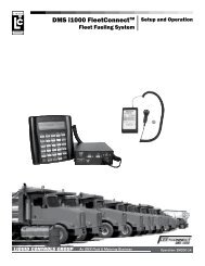
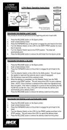
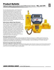
<strong>LCR</strong>-<strong>II</strong> System Components<br />
Communication <strong>and</strong><br />
Programming Devices<br />
Pump & Print<br />
Lap Pad H<strong>and</strong> Held Computer Laptop Computer<br />
4
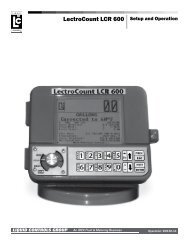
<strong>LCR</strong>-<strong>II</strong> Overview<br />
This manual provides instructions for the initial set<strong>up</strong>, the calibration, <strong>and</strong> the operation of LectroCount <strong>LCR</strong>-<strong>II</strong> software,<br />
also known as SR260 firmware. The <strong>Liquid</strong> <strong>Controls</strong> LectroCount <strong>LCR</strong>-<strong>II</strong> is a microprocessor-based electronic meter<br />
register available in a Division 1 or a Division 2 enclosure. Its primary functions consists of configuring the meter<br />
system to the properties of the liquids to be measured, interfacing with the electronic components of the meter system<br />
components (<strong>and</strong> external components such as pumps, injectors, <strong>and</strong> shutdown devices), <strong>and</strong> performing Weights &<br />
Measures approved custody transfer actions.<br />
The <strong>LCR</strong>-<strong>II</strong> performs well in mobile <strong>and</strong> fixed installations. It can control a meter system as a st<strong>and</strong>-alone unit or used<br />
as a slave to a host controller such as a process controller or an in-cab data management system.<br />
The LectroCount <strong>LCR</strong>-<strong>II</strong> features include:<br />
• Full Weights & Measures Approvals<br />
• Class I, Division 2, Gro<strong>up</strong> C, D safety approvals.<br />
• NEMA 4X enclosure with hinged display panel featuring single connection latch bolt, Weights & Measures sealable<br />
• (2) ¾" <strong>and</strong> (5) ½" conduit connections<br />
• <strong>Operation</strong> with most flowmeters. <strong>LCR</strong>-<strong>II</strong> accepts input from PD, Amplified Turbine, Electromagnetic <strong>and</strong> Mass<br />
flowmeters.<br />
• Multi-Point Calibration for improved meter accuracy over the full flow range<br />
• Multiple Product Calibration<br />
• Optional Electronic Temperature Volume Compensation (ETVC)<br />
• Large character, backlit LCD display<br />
• 10 digit totalizer<br />
• Two control buttons on front panel provide:<br />
• "SELECT" for accessing internal menus<br />
• "INCREASE" for adjusting internal programmable data<br />
• Push button presetting, rate of flow indication, temperature indication, product selection <strong>and</strong> more.<br />
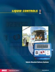
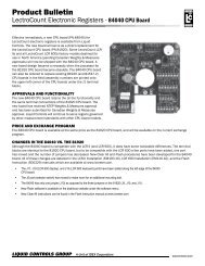
LectroCount <strong>LCR</strong>-<strong>II</strong> Division 1<br />
Enclosure<br />
LectroCount <strong>LCR</strong>-<strong>II</strong> Division 2<br />
Enclosure<br />
5
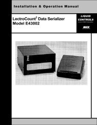
Lap Pad <strong>Operation</strong><br />
LAP PAD OVERVIEW<br />
This section of the manual provides instructions for the<br />
initial set-<strong>up</strong>, calibration <strong>and</strong> operation of your <strong>LCR</strong>-<strong>II</strong><br />
Electronic Register using the <strong>Liquid</strong> <strong>Controls</strong> Lap Pad<br />
data entry device. This section should first be scanned<br />
to become familiar with the components of the system,<br />
the layout <strong>and</strong> format of the document, the basic menu<br />
(screens) <strong>and</strong> data entry required. This section should<br />
then be carefully followed as the system is being set <strong>up</strong><br />
<strong>and</strong> calibrated. (Refer to the Installation <strong>Manual</strong> for<br />
instructions on connecting the Lap Pad for use with the<br />
<strong>LCR</strong>-<strong>II</strong>).<br />
Following is a brief overview of the top level Program<br />
Menu screens.<br />
DELIVERY & PRESET<br />
This menu includes <strong>up</strong> to seven data screens for setting preset quantities, product prices, taxes <strong>and</strong><br />
other relevant delivery information.<br />
PRODUCT & SHIFT INFORMATION<br />
This menu includes four secondary data screens for viewing product types <strong>and</strong> basic parameters<br />
pertaining to shift information.<br />
GENERAL SET-UP<br />
This menu includes five secondary data screens for setting the internal clock <strong>and</strong> calendar, initializing<br />
sale <strong>and</strong> ticket number counters, setting the no-flow timer <strong>and</strong> defining data to be printed on tickets.<br />
SYSTEM CALIBRATION<br />
This menu includes five secondary screens for entering Meter ID, printer selections, units of measure,<br />
rounding <strong>and</strong> truncating.<br />
PRODUCT CALIBRATION<br />
This menu includes eight secondary screens for assigning unique codes to products; defining product<br />
types such as gasoline, diesel fuel, LPG, etc.; <strong>and</strong> compensation parameters such as base temperature<br />
for temperature compensated deliveries.<br />
DIAGNOSTICS<br />
This menu includes four secondary screens for viewing system parameters such as software version,<br />
s<strong>up</strong>ply voltage, <strong>and</strong> pulser diagnostic information.<br />
SECURITY<br />
This menu includes one secondary screen for user password <strong>and</strong> system security.<br />
6
NAVIGATING TOP-LEVEL MENUS<br />
When the <strong>LCR</strong>-<strong>II</strong> is powered <strong>up</strong> with a Lap Pad attached, the Lap Pad will briefly display a copyright message for two<br />
seconds followed by the initial top-level menu.<br />
DELIVERY & PRESET<br />
Press Enter or Scroll with ARROW keys.<br />
Lap Pad <strong>Operation</strong><br />
Press the key to navigate to the next top-level menu.<br />
Continue pressing the key to scroll through the rest of the top-level menus (as seen below).<br />
Press the key to navigate in the opposite direction.<br />
Selecting a secondary menu is accomplished by pressing the ENTER key.<br />
Pressing the , , M1 <strong>and</strong> M# keys allows for navigation of the secondary level screens.<br />
DELIVERY & PRESET<br />
Press Enter or Scroll with ARROW keys.<br />
PRODUCT & SHIFT INFORMATION<br />
Press Enter or Scroll with ARROW keys.<br />
GENERAL SETUP<br />
Press Enter or Scroll with ARROW keys.<br />
SYSTEM CALIBRATION<br />
Press Enter or Scroll with ARROW keys.<br />
PRODUCT CALIBRATION<br />
Press Enter or Scroll with ARROW keys.<br />
DIAGNOSTICS<br />
Press Enter or Scroll with ARROW keys.<br />
SECURITY<br />
Press Enter or Scroll with ARROW keys.<br />
7
Lap Pad <strong>Operation</strong><br />
SECONDARY DATA SCREENS<br />
Each of the top-level menus has a secondary level consisting of one or more screens. Each screen is divided into one<br />
or more fields where data may be entered or information displayed. Access to data entry is dependent on the following:<br />
DATA FIELD TYPE:<br />
Some fields are for display only <strong>and</strong> data entry is not necessary (e.g. DIAGNOSTICS <strong>and</strong> FLOW<br />
RATE).<br />
PASSWORD PROTECTION:<br />
The <strong>LCR</strong>-<strong>II</strong> has a user-definable password that allows the system to be locked. This feature authorizes<br />
a s<strong>up</strong>ervisor to limit access to certain fields. An operator can still view all data fields whether the unit<br />
is locked or unlocked. Data entry in general system set-<strong>up</strong> functions (e. g. NO-FLOW TIMER <strong>and</strong><br />
PRESET TYPE) are still accessible if the system is locked.<br />
SELECTOR SWITCH:<br />
The multi-position Selector Switch on the front of the <strong>LCR</strong>-<strong>II</strong> has a CALIBRATION position that is<br />
accessed by removing a Weights & Measures sealable plate. This allows data entry in the metrologically<br />
significant fields (e. g. COMPENSATION TYPE, TEMPERATURE PULSES/UNIT <strong>and</strong> others).<br />
When a secondary menu is entered by pressing the ENTER key, the cursor will be positioned in the top line of the first<br />
field. Pressing will cause the cursor to move to the next field.<br />
Repeatedly pressing will move the cursor through the fields from left to right. After the right most field, the next<br />
secondary menu screen will be displayed. The cursor will be in the first field. After the last field of the last screen, the<br />
cursor returns to the top line of the first field of the first screen.<br />
NOTE: Pressing the "M#" key scrolls forward to the next secondary menu. Pressing "M1" returns the display to the toplevel<br />
menu from any secondary level menu.<br />
The cursor indicates if data can be entered or changed in the field below it. If the cursor is flashing, pressing ENTER<br />
will move the cursor to the second line in the field <strong>and</strong> data may be entered or changed. In some cases, data is entered<br />
using the keypad. In other cases, data is entered by selecting entries using the keys. A "^" Character in the top line<br />
of the field indicates that a scroll list is used for the field. In fields that have a "", a "YES" or "NO" response is selected.<br />
Information that is entered through the Lap Pad or selected from a menu of choices is stored in the <strong>LCR</strong>-<strong>II</strong> by pressing<br />
ENTER. The cursor also moves back to the top line of that menu screen.<br />
Menu maps of the screens accessible in the system are located in Appendix D on pages 50-57.<br />
The next section covers Calibration & <strong>Set</strong>-<strong>up</strong> using the Lap Pad.<br />
8
BEFORE GETTING STARTED<br />
Lap Pad Calibration & <strong>Set</strong>-Up<br />
• Make sure that the Lap Pad or other data entry device is connected to the <strong>LCR</strong>-<strong>II</strong> register as described in the <strong>LCR</strong>-<br />
<strong>II</strong> Installation <strong>Manual</strong>.<br />
• When proving the <strong>LCR</strong>-<strong>II</strong> system, follow the pre-test <strong>and</strong> inspection procedures established by Weights & Measures<br />
authorities. The primary indicating <strong>and</strong> recording element on a vehicle-mounted <strong>LCR</strong>-<strong>II</strong> is the 6-digit liquid crystal<br />
display.<br />
• Weights & Measures inspectors are responsible for determining if the truck metering <strong>and</strong> recording elements of the<br />
system are within tolerance. To make this determination, the system should be tested under normal conditions.<br />
• The <strong>LCR</strong>-<strong>II</strong> is pre-programmed with common values for many of the programmable parameters. These values<br />
should be checked to ensure that they fit the specific requirements of the given installation. Detailed instructions<br />
for checking <strong>and</strong> changing these values follow later in this publication.<br />
• Changes cannot be made to metrologically significant data without first removing the Switchplate <strong>and</strong> its associated<br />
Weights & Measures seal. The security level for each of the programming screens is defined in the following table:<br />
OPERATOR<br />
PASSWORD<br />
WEIGHTS & MEASURES<br />
FACTORY<br />
NOT EDITBLE<br />
Operato can change or enter data.<br />
System must be unlocked.<br />
Switch must be in the CALIBRATION position to enter or<br />
change data.<br />
Read only (can not be changed by operator).<br />
Read only (can not be changed by operator).<br />
NOTE: This table applies to the lower line of the Lap Pad display only. The <strong>up</strong>per line cannot be edited.<br />
STEP 1: REMOVE THE <strong>LCR</strong>-<strong>II</strong><br />
SWITCHPLATE<br />
• Remove the lead seal <strong>and</strong> wire assembly from the<br />
<strong>LCR</strong>-<strong>II</strong> Switchplate (if previously sealed by Weights<br />
& Measures authorities).<br />
• Remove the four screws that secure the Switch Plate<br />
over the red Selector Switch located on the front of<br />
the <strong>LCR</strong>-<strong>II</strong>, <strong>and</strong> remove the plate.<br />
• Rotate the Selector Switch counter clockwise to the<br />
6 o'clock (CALIBRATION) position to permit access<br />
to all programming fields (except FACTORY).<br />
9
Lap Pad Calibration & <strong>Set</strong>-Up<br />
STEP 2: SECURITY<br />
Press the M1 Key to access a top-level menu. Press to scroll to the SECURITY menu. Press ENTER to<br />
gain access to the secondary menu.<br />
Security - Screen 1<br />
USER KEY SECURITY^<br />
0001<br />
UNLOCKED<br />
USER KEY (Password)<br />
Use this field to enter the owner/office password. To enter a password, press ENTER to drop into the<br />
data entry field. Enter a password using <strong>up</strong> to 10 alphanumeric characters. Press ENTER. This<br />
password will be required in the future to unlock the system in order to gain access to secured menu<br />
<strong>and</strong> data entry fields. This password will also be needed to change the time using the <strong>LCR</strong>-<strong>II</strong> control<br />
buttons. If it is desired to have access to time adjustment, the USER KEY must be numeric only <strong>and</strong><br />
contain 5 digits.<br />
Press <strong>and</strong> the cursor will move to:<br />
SECURITY^<br />
This field is used to lock the system. Press ENTER to drop to the bottom field. Use i to scroll between<br />
LOCKED <strong>and</strong> UNLOCKED. Press ENTER to select the desired option. While the system is LOCKED,<br />
the operator is unable to change system data other than GROSS <strong>and</strong> NET PRESETS, PRODUCT<br />
CODE, PRODUCT NAME, <strong>and</strong> NO-FLOW TIMER.<br />
NOTE: The <strong>LCR</strong>-<strong>II</strong> is shipped LOCKED from the factory.<br />
Press M1 to return to the top-level menu. Press to scroll to GENERAL SETUP.<br />
STEP 3: GENERAL SETUP<br />
The fields in this menu are not specific to any of the four possible product calibrations, therefore the<br />
Selector Switch does not have to be in the CALIBRATION position to allow data entry in many of these<br />
fields <strong>and</strong> changes can be made without breaking Weights & Measures seals.<br />
Press ENTER <strong>and</strong> the cursor will move to:<br />
General <strong>Set</strong><strong>up</strong> - Screen 1<br />
DATE FORMAT^ DATE<br />
MM/DD/YY<br />
10/6/2002<br />
TIME HH:MM:SS<br />
9:05:24<br />
DATE FORMAT^<br />
This field is used to determine in which format the date will be displayed <strong>and</strong> printed: month first or day<br />
first. Press ENTER <strong>and</strong> the cursor will drop to the second line. Now you can use the arrow keys to<br />
select the format, either month first (MM/DD/YY) or day first (DD/MM/YY). When the choice is displayed,<br />
press ENTER <strong>and</strong> the cursor will move back to the top line.<br />
Press <strong>and</strong> the cursor will move to:<br />
DATE MM/DD/YY (or DD/MM/YY depending on the previous field).<br />
This field is used to set the <strong>LCR</strong>-<strong>II</strong> internal calendar. The <strong>LCR</strong>-<strong>II</strong> <strong>up</strong>dates its calendar <strong>and</strong> will print the<br />
correct date on delivery tickets. Press ENTER <strong>and</strong> the cursor will drop to the bottom line. Enter the<br />
current date on the keypad using only numbers. Press ENTER <strong>and</strong> the cursor will move back to the top<br />
line.<br />
10
Lap Pad Calibration & <strong>Set</strong>-Up<br />
STEP 3: GENERAL SETUP CONTINUED<br />
Press <strong>and</strong> the cursor will move to:<br />
TIME HH:MM:SS<br />
This field is used to set the <strong>LCR</strong>-<strong>II</strong> internal clock. The time, like the date, is <strong>up</strong>dated by the <strong>LCR</strong>-<strong>II</strong> <strong>and</strong><br />
printed on the delivery tickets. Press ENTER <strong>and</strong> the cursor will drop to the bottom line. Enter the<br />
current hour, minutes, <strong>and</strong> seconds. Use military time (e.g. press 13:01:15 for 1:01:15 PM).<br />
HINT: To synchronize the clock to the second, press ENTER when the appropriate second is reached.<br />
Press ENTER <strong>and</strong> the cursor will move to the top line.<br />
Press <strong>and</strong> the cursor will move to:<br />
General <strong>Set</strong><strong>up</strong> - Screen 2<br />
SALE# TICKET#<br />
25<br />
1<br />
UNIT ID<br />
123456<br />
NO-FLOW TIMER<br />
180<br />
SALE #<br />
This field is used to track the number of transactions that the <strong>LCR</strong>-<strong>II</strong> processes. The <strong>LCR</strong>-<strong>II</strong> will increment<br />
the field each time a delivery is made, wrapping around to 000000 after 999999. Press ENTER <strong>and</strong> the<br />
cursor will drop to the bottom line. Key in the starting SALE #, <strong>up</strong> to 6 digits. Press ENTER <strong>and</strong> the<br />
cursor will move to the top line.<br />
Press <strong>and</strong> the cursor will move to:<br />
TICKET #<br />
This is similar to the sale number. It will increment every time that the <strong>LCR</strong>-<strong>II</strong> prints a ticket. If multiple<br />
or d<strong>up</strong>licate tickets are used for transactions, the ticket number will be incremented more than the sale<br />
number. NOTE: If a TICKET # of 0 is entered, the TICKET # will not print on the delivery ticket <strong>and</strong> the<br />
TICKET # will not increment. Press ENTER <strong>and</strong> the cursor will drop to the bottom line. Key in the<br />
starting TICKET #, <strong>up</strong> to 6 digits. Press ENTER <strong>and</strong> the cursor will move to the top line.<br />
Press <strong>and</strong> the cursor will move to:<br />
UNIT ID<br />
This is a number that can be used to identify the driver, location, or truck that the <strong>LCR</strong>-<strong>II</strong> is associated<br />
with. Press ENTER <strong>and</strong> the cursor will drop to the bottom line. Key in your UNIT ID, <strong>up</strong> to 10 characters.<br />
Press ENTER <strong>and</strong> the cursor will move to the top line.<br />
Press <strong>and</strong> the cursor will move to:<br />
NO-FLOW TIMER<br />
The NO-FLOW TIMER is an internal timer in the <strong>LCR</strong>-<strong>II</strong> that starts running when the <strong>LCR</strong>-<strong>II</strong> senses<br />
that there is no longer any product moving through the meter. If the timer counts <strong>up</strong> to its set point, the<br />
<strong>LCR</strong>-<strong>II</strong> will assume that the delivery is over, <strong>and</strong> print a ticket. The timer can be set to count <strong>up</strong> to 3600<br />
seconds before printing the ticket. This feature can be deactivated by entering 0 seconds, allowing<br />
multiple tanks to be filled at a location. The timer helps to ensure that deliveries are not split between<br />
authorized <strong>and</strong> unauthorized locations. NO-FLOW TIMER is not active in prover mode. If the value is<br />
set to 0 or any value greater than 180, "Multiple Deliveries at One Site" will be printed on the delivery<br />
ticket.<br />
NOTE: Internal timer is activated once the flow delivery has started <strong>and</strong> a minimum amount of flow (1<br />
gallon or 5 liters) is registered <strong>and</strong> then is stopped.<br />
11
Lap Pad Calibration & <strong>Set</strong>-Up<br />
STEP 3: GENERAL SETUP CONTINUED<br />
NO-FLOW TIMER CONTINUED<br />
Press ENTER <strong>and</strong> the cursor will drop to the bottom line. Enter the desired NO-FLOW TIMER value<br />
inseconds. Press ENTER <strong>and</strong> the cursor will move to the top line.<br />
Press <strong>and</strong> the cursor will move to:<br />
General <strong>Set</strong><strong>up</strong> - Screen 3<br />
PRESET^<br />
PRESET TYPE^<br />
GROSS<br />
CLEAR<br />
PULSE OUTPUT EDGE^<br />
RISING<br />
PRESET^<br />
Available preset options include NET, BOTH, GROSS, <strong>and</strong> NONE. Selecting NONE will disable<br />
presetting. Presetting NET, GROSS, or BOTH is allowed. Press ENTER <strong>and</strong> the cursor will drop to the<br />
bottom line. Use to scroll through the available preset options. When the desired option is displayed,<br />
press ENTER <strong>and</strong> the cursor will move to the top line.<br />
Press <strong>and</strong> the cursor will move to:<br />
PRESET TYPE^<br />
There are four preset types:<br />
CLEAR<br />
Resets the preset values to 0 after the current delivery is ended.<br />
RETAIN<br />
Maintains the preset values to be used again on the next delivery.<br />
MULTIPLE<br />
Allows more than one preset to be run before a delivery ticket is printed. Printing must be<br />
initiated by a PRINT comm<strong>and</strong>.<br />
INVENTORY<br />
Maintains the remaining preset amount between deliveries (i. e. indicates the remaining volume<br />
in the vehicle tank).<br />
Press ENTER <strong>and</strong> the cursor will drop to the bottom line. Use to scroll through the four options.<br />
When the desired choice is displayed, press ENTER <strong>and</strong> the cursor will move to the top line.<br />
Press <strong>and</strong> the cursor will move to:<br />
PULSE OUTPUT EDGE^<br />
This feature allows you to synchronize the calibrated pulse output waveform with the requirements of<br />
an external system that uses that <strong>LCR</strong>-<strong>II</strong> signal. There are two choices: RISING or FALLING. (Some<br />
counters increment on rising, others on falling pulse edges. Refer to equipment technical manual to<br />
determine the specific requirements of your connected equipment). Press ENTER <strong>and</strong> the cursor will<br />
drop to the bottom line. Use to scroll between the two choices. When the desired choice is displayed,<br />
press ENTER <strong>and</strong> the cursor will move to the top line.<br />
Press <strong>and</strong> the cursor will move to:<br />
12
Lap Pad Calibration & <strong>Set</strong>-<strong>up</strong><br />
STEP 3: GENERAL SETUP CONTINUED<br />
General <strong>Set</strong><strong>up</strong> - Screen 4<br />
HDR^<br />
TICKET HEADER LINE<br />
1<br />
HDR^<br />
This field is used to select the line number of the ticket header that will be edited in the following field.<br />
Press ENTER <strong>and</strong> the cursor will drop to the bottom line. Use the keys to scroll through the numbers<br />
from 1 to 12. When the desired choice is displayed, press the ENTER key <strong>and</strong> the cursor will move to<br />
the top line.<br />
Press <strong>and</strong> the cursor will move to:<br />
TICKET HEADER LINE<br />
This feature is useful when using blank (as opposed to pre-printed) tickets. The field allows the fuel<br />
dealer to enter the company name, address, telephone number, etc., which will be printed on each<br />
delivery ticket. This field (35-character max.) allows you to enter or edit ticket header labels. The<br />
Header Line will scroll in t<strong>and</strong>em with the HDR # selected in the previous field. Any lines that are left<br />
blank will not be printed on the ticket.<br />
NOTE: Header Lines 11 <strong>and</strong> 12 can only be edited in the CALIBRATION mode. TICKET HEADER<br />
LINE 11 only prints when AUX OUT 1 is ON or ON DURING DELIVERY as shown on the Lap Pad<br />
Screen. TICKET HEADER LINE 12 only prints when AUX OUT 2 is ON or ON DURING DELIVERY.<br />
After data has been entered, press ENTER.<br />
Press <strong>and</strong> the cursor will move to:<br />
General <strong>Set</strong><strong>up</strong> - Screen 5<br />
PRINT GROSS & PARAM<br />
YES<br />
VOL CORRECTED MSG<br />
YES<br />
PRINT GROSS & PARAM<br />
This allows one to choose whether to have the gross volume <strong>and</strong> compensation parameter printed on<br />
the ticket if the product is temperature compensated. Press ENTER <strong>and</strong> the cursor will drop to the<br />
bottom line. Use to scroll between the two choices, YES or NO. When the desired choice is displayed,<br />
press the ENTER key <strong>and</strong> the cursor will move to the top line.<br />
Press <strong>and</strong> the cursor will move to:<br />
VOL CORRECTED MSG<br />
This field allows you to print a message on the delivery ticket indicating that delivery volume has been<br />
corrected to a base temperature (defined later in SYSTEM CALIBRATION). The user has the option<br />
(YES or NO) to print the message. Press ENTER <strong>and</strong> the cursor will drop to the bottom line. Use to<br />
scroll between the two choices, YES or NO. When the desired choice is displayed, press the ENTER<br />
key <strong>and</strong> the cursor will move to the top line. Press M1 to return to the top of the GENERAL SETUP<br />
menu.<br />
13
Lap Pad Calibration & <strong>Set</strong>-<strong>up</strong><br />
STEP 4: SYSTEM CALIBRATION<br />
From the top-level menu, use to scroll to SYSTEM CALIBRATION. Press ENTER <strong>and</strong> the cursor will move to:<br />
System Calibration - Screen 1<br />
METER ID<br />
TICKET PRINTER<br />
1234567890 YES EPSON NewFontB<br />
METER ID<br />
This number allows you to uniquely identify an <strong>LCR</strong>-<strong>II</strong>/Meter combination. If the <strong>LCR</strong>-<strong>II</strong> is part of a<br />
multiple-meter system, it is important that this number be unique. It is recommended that the meter<br />
serial number be entered here. This number will print on the calibration/diagnostic ticket. Press<br />
ENTER <strong>and</strong> the cursor will drop tot he bottom line. Key in 1 to 10 characters. Press ENTER <strong>and</strong> the<br />
cursor will move back to the top line.<br />
Press <strong>and</strong> the cursor will move to:<br />
TICKET<br />
This field allows you to choose whether or not a ticket will be required for each delivery. Most Weights<br />
& Measures governed truck applications will require a ticket. If YES is chosen, the <strong>LCR</strong>-<strong>II</strong> will not allow<br />
deliveries to be made unless a ticket is in the printer, the printer is operational <strong>and</strong> the previous delivery<br />
ticket has been printed in its entirety. Press ENTER <strong>and</strong> the cursor will drop to the bottom line. Use <br />
to scroll between the two choices, YES or NO. When the desired choice is displayed, press ENTER.<br />
The cursor will move to the top line. When NO is selected, tickets are not m<strong>and</strong>atory but will print if a<br />
printer is connected <strong>and</strong> available to print a ticket.<br />
Press <strong>and</strong> the cursor will move to:<br />
PRINTER^<br />
This field allows you to select a printer type. The six choices are EPSON NewFontB (select for use<br />
with EPSON 200 Roll <strong>and</strong> EPSON 220 Roll). EPSON NewFontA (select for use with EPSON TM-<br />
T88iii), EPSON OldFontA (select for use with EPSON 290 Slip <strong>and</strong> EPSON 295 Slip), EPSON OldFontB<br />
(select for use with EPSON 300 Roll), OKIDATA ML184T (select for use with Okidata ML184T),<br />
BLASTER (select for use with Cognitive Solutions Thermal Printer). Press ENTER <strong>and</strong> the cursor will<br />
drop to the bottom line. Use to scroll between the choices. When the desired choice is displayed,<br />
press ENTER <strong>and</strong> the cursor will move back to the top line.<br />
Press to move to:<br />
System Calibration - Screen 2<br />
UNITS^ RATE BASE^<br />
GALONS PER MINUTE<br />
DECIMAL^<br />
TENTHS<br />
RESIDUAL^<br />
ROUND<br />
UNITS^<br />
This field is used to choose the units of flow measurement. The choices are GALLONS, LITRES,<br />
CUBIC M, LBS (pounds), KGS (kilograms), BARRELS, <strong>and</strong> OTHER. Press ENTER <strong>and</strong> the cursor<br />
will drop to the bottom line. Use the keys to scroll through the choices. When the desired choice is<br />
displayed, press ENTER <strong>and</strong> the cursor will move to the top line.<br />
Press <strong>and</strong> the cursor will move to:<br />
RATE BASE^<br />
Use this field to select the time unit for measurement on the flow rate display. The choices are rate PER<br />
HOUR, PER MINUTE <strong>and</strong> PER SECOND. Press ENTER <strong>and</strong> the cursor will drop to the bottom line.<br />
Use to scroll between the three choices. When the desired choice is displayed, press ENTER <strong>and</strong><br />
the cursor will move to the top line.<br />
Press <strong>and</strong> the cursor will move to:<br />
14
Lap Pad Calibration & <strong>Set</strong>-<strong>up</strong><br />
STEP 4: SYSTEM CALIBRATION CONTINUED<br />
DECIMAL^<br />
This field allows you to choose between whole units, tenths <strong>and</strong> hundredths of a unit. Press ENTER<br />
<strong>and</strong> the cursor will drop to the bottom line. Use to scroll between WHOLE, TENTHS, <strong>and</strong> HUNDR.<br />
When the desired choice is displayed press ENTER <strong>and</strong> the cursor will move to the top line.<br />
Press <strong>and</strong> the cursor will move to:<br />
RESIDUAL^<br />
Volumes less than the least significant digit can be rounded into that digit or truncated (thrown away)<br />
depending on the selection mode. Press ENTER <strong>and</strong> the cursor will drop to the bottom line. Press to<br />
scroll between ROUND <strong>and</strong> TRUNCATE. When the desired choice is displayed press ENTER <strong>and</strong> the<br />
cursor will move to the top line.<br />
Press <strong>and</strong> the cursor will move to:<br />
System Calibration - Screen 3<br />
TEMP<br />
25.53<br />
OFFSET<br />
0.00<br />
T TEMP^<br />
DEG. F<br />
RTD SLP<br />
0.024724<br />
RTD OFS<br />
2.817<br />
TEMP<br />
This field displays the current temperature reading from the RTD temperature probe <strong>and</strong> allows one to<br />
enter a corrected value from a Weights & Measures thermometer. If the <strong>LCR</strong>-<strong>II</strong> is not equipped with the<br />
optional Electronic Temperature Volume Compensation (ETVC) Kit, this field will read "--".<br />
To make a correction:<br />
Run enough product through the meter to allow the temperature to stabilize. Compare the<br />
TEMP reading with the current Weights & Measures thermometer reading. If the readings are<br />
different, the Weights & Measures reading should be entered. Press ENTER <strong>and</strong> the cursor<br />
will drop to the bottom line. Enter the new value. The new value will overwrite the previous one<br />
<strong>and</strong> the OFFSET field will be recalculated by the <strong>LCR</strong>-<strong>II</strong>. Offset adjustments are limited to<br />
±0.3°C (±0.54°F). Adjustments greater than this limit require replacement of the RTD probe.<br />
Press ENTER <strong>and</strong> the cursor will move to the top line.<br />
Press <strong>and</strong> the cursor will move to:<br />
OFFSET<br />
The offset represents the difference between the official Weights & Measures reading <strong>and</strong> the <strong>LCR</strong>-<strong>II</strong><br />
RTD reading. The offset is automatically calculated if an entry is made in the previous field.<br />
If a Weights & Measures thermometer reading was not entered in the previous field, subtract the value<br />
listed in the TEMP field from the Weights & Measures measurement. Key in the difference in the offset<br />
field. If the number is negative, use "*" on the Lap Pad to change the sign. Adjustment is limited to<br />
±0.3°C (±0.54°F). Any adjustment larger than ±0.3°C (±0.54°F) generates a " RANGE ERROR" message<br />
<strong>and</strong> requires replacement of the RTD probe.<br />
Press <strong>and</strong> the cursor will move to:<br />
15
Lap Pad Calibration & <strong>Set</strong>-<strong>up</strong><br />
STEP 4: SYSTEM CALIBRATION CONTINUED<br />
T UNIT^<br />
This field allows you to choose the temperature units - Degrees Fahrenheit or Degrees Celsius. Press<br />
ENTER <strong>and</strong> the cursor will drop to the bottom line. Use to scroll between the two choices, DEG. F<br />
<strong>and</strong> DEG. C. When the desired choice is displayed, press ENTER <strong>and</strong> the cursor will move to the top<br />
line.<br />
Press <strong>and</strong> the cursor will move to:<br />
RTD SLP<br />
Factory calibration setting only. Press <strong>and</strong> the cursor will move to:<br />
RTD OFS<br />
Factory calibration setting only. Press <strong>and</strong> the cursor will move to:<br />
System Calibration - Screen 4<br />
FLOW DIR^ LAST CALIBRATED<br />
--><br />
7/11/2002 11:44<br />
FLOW DIR^<br />
This field allows you to match the <strong>LCR</strong>-<strong>II</strong> flow direction to the meter's pulse output. If the counter runs<br />
backwards, this arrow should be changed. The choices are or . Press ENTER <strong>and</strong> the cursor will<br />
drop to the bottom line. Use to scroll between the two choices. When the desired choice is displayed,<br />
press ENTER.<br />
Press <strong>and</strong> the cursor will move to:<br />
LAST CALIBRATED<br />
This field contains the date <strong>and</strong> time of the last calibration. It cannot be edited.<br />
Press <strong>and</strong> the cursor will move to:<br />
<strong>LCR</strong> #<br />
250<br />
<strong>LCR</strong> #<br />
This field contains the node address for RS485 communication. Enter a number between 1 <strong>and</strong> 250.<br />
The default value is 250.<br />
Press <strong>and</strong> the cursor will move to:<br />
System Calibration - Screen 5<br />
CALIB#<br />
CALIB EVENT<br />
34<br />
19<br />
CONFIG EVENT<br />
1<br />
CALIB #<br />
For metrology use only. This is the number of times the calibration switch position has been entered.<br />
DISPLAY ONLY.<br />
CALIB EVENT<br />
For metrology use only. This is the number of times the calibration has been changed. DISPLAY ONLY.<br />
CONFIG EVENT<br />
For metrology use only. This is the number of times the configuration has been changed. DISPLAY<br />
ONLY.<br />
Press the M1 key to return to the top of the SYSTEM CALIBRATION menu. Then press to scroll to PRODUCT &<br />
SHIFT INFORMATION.<br />
16
Lap Pad Calibration & <strong>Set</strong>-<strong>up</strong><br />
STEP 5: PRODUCT & SHIFT INFORMATION<br />
Press ENTER <strong>and</strong> the cursor will move to:<br />
Product & Shift - Screen 1<br />
#^<br />
PROD TYPE<br />
1<br />
DISTILLATE<br />
SHIFT START<br />
7/01/2002 1:44:00<br />
DLVRY<br />
22<br />
#^ (Product Number)<br />
This field is used to select one of four possible product types/calibrations. Press ENTER <strong>and</strong> the<br />
cursor will drop to the bottom line. Use to scroll through the numbers 1-4. When the product number<br />
is selected for which corresponding PROD TYPE^ information will be entered, press ENTER <strong>and</strong> the<br />
cursor will move to the top line.<br />
Press <strong>and</strong> the cursor will move to:<br />
PROD TYPE^<br />
This field will scroll along with the #^(Product Number) that is shown in the first field. The product type<br />
AMMONIA, AVIATION, DISTILLATE, GASOLINE, METHANOL, LPG, LUBE OIL or "blank" can be<br />
selected. Press ENTER <strong>and</strong> the cursor will drop to the bottom line. Press to scroll through the<br />
available options. When the desired choice is displayed, press ENTER <strong>and</strong> the cursor will move to the<br />
top line.<br />
Press <strong>and</strong> the cursor will move to:<br />
SHIFT START<br />
The starting time <strong>and</strong> date for the current shift are shown here. DISPLAY ONLY.<br />
DLVRY<br />
This field shows the number of deliveries that have been made since the last time CLR SHIFT was set<br />
to YES or a shift ticket was printed. DISPLAY ONLY.<br />
Press <strong>and</strong> the cursor will move to:<br />
Product & Shift - Screen 2<br />
#^<br />
SHIFT GROSS<br />
1<br />
1647.6<br />
SHIFT NET<br />
0.0<br />
UNITS<br />
GALLONS<br />
#^ (Product Number)<br />
This field is used to select one of four possible product types/calibrations that can be set <strong>up</strong> in the <strong>LCR</strong>-<br />
<strong>II</strong>. At least one calibration must be set <strong>up</strong> to allow deliveries.<br />
SHIFT GROSS<br />
This field displays the gross number of units that have been delivered through the meter since the last<br />
time the CLR SHIFT field was set to YES or a shift ticket was printed. SHIFT GROSS is the sum total<br />
of the delivery ticket gross quantities during the current shift. DISPLAY ONLY.<br />
Press <strong>and</strong> the cursor will move to:<br />
SHIFT NET<br />
This field displays the net (temperature compensated) number of units that have been delivered through<br />
the meter since the last time CLR SHIFT field was set to YES or a shift ticket was printed. SHIFT NET<br />
is the sum total of the delivery ticket net quantities during the current shift. DISPLAY ONLY.<br />
17
Lap Pad Calibration & <strong>Set</strong>-<strong>up</strong><br />
STEP 5: PRODUCT & SHIFT INFORMATION CONTINUED<br />
UNITS^<br />
From this field, a unit of measure is selected. Choose GALLONS, LITRES, CUBIC M, LBS (pounds),<br />
KGS (kilograms), BARRELS, or OTHER.<br />
Press <strong>and</strong> the cursor will move to:<br />
Product & Shift - Screen 3<br />
#^<br />
GROSS TOTAL<br />
1<br />
6193.8<br />
NET TOTAL<br />
0.0<br />
UNITS<br />
GALLONS<br />
#^ (Product Number)<br />
This field is used to select one of four possible product types/calibrations. At least one calibration must<br />
be set <strong>up</strong> in the <strong>LCR</strong>-<strong>II</strong> to allow deliveries.<br />
GROSS TOTAL<br />
This field shows the total gross volume that has gone through the register since the field was last<br />
initialized. This value can be initialized to any positive number if the Selector Switch is in the<br />
CALIBRATION position. This is a "live" totalizer <strong>and</strong> will count regardless of a delivery being active.<br />
Press <strong>and</strong> the cursor will move to:<br />
NET TOTAL<br />
This field shows the total net volume that has gone through the register since the field was last initialized.<br />
This value can be initialized to any positive value if the Selector Switch is in the CALIBRATION position.<br />
This is a "live" totalizer <strong>and</strong> will count regardless of a delivery being active.<br />
Press <strong>and</strong> the cursor will move to:<br />
UNITS^<br />
From this field, a unit of measure is selected. Choose from GALLONS, LITRES, CUBIC M, LBS<br />
(pounds), KGS (kilograms), BARRELS, or OTHER. If more than one product is entered, the above<br />
listed procedures should be repeated for each.<br />
Press <strong>and</strong> the cursor will move to:<br />
Product & Shift - Screen 4<br />
CLR SHIFT<br />
NO<br />
CLR SHIFT<br />
This field is used to print a SHIFT TICKET <strong>and</strong> clear the SHIFT GROSS, SHIFT NET, <strong>and</strong> DLVRY<br />
fields. If YES is selected, the shift fields will be reset to 0 after the shift ticket is printed. After the ticket<br />
is printed, this field will revert to NO. If TICKET is set to NO, shift totals can be cleared without<br />
printing a shift ticket. Press ENTER <strong>and</strong> the cursor will drop to the bottom line.<br />
Press the key to scroll between YES <strong>and</strong> NO. When the desired entry is displayed, press ENTER <strong>and</strong> the cursor will<br />
return to the top line.<br />
18
Lap Pad Calibration & <strong>Set</strong>-<strong>up</strong><br />
STEP 6: PRODUCT CALIBRATION<br />
Press M1 to return to the top-level menu. Press i to scroll to PRODUCT CALIBRATION.<br />
There are four product calibrations that can be set <strong>up</strong> in the <strong>LCR</strong>-<strong>II</strong>. The products are calibrated one at a time. Press<br />
ENTER <strong>and</strong> the cursor will move to:<br />
Product Calibration - Screen 1<br />
#^<br />
CODE<br />
PRODUCT NAME<br />
1<br />
12345 Product Name<br />
PRODUCT TYPE<br />
DISTILLATE<br />
#^(Product Number)<br />
This number will correspond to one of the four product types/calibrations that can be set <strong>up</strong> in the <strong>LCR</strong>-<br />
<strong>II</strong>. At least one calibration must be set <strong>up</strong> to allow deliveries. Press ENTER <strong>and</strong> the cursor will drop to<br />
the bottom line. Use i to scroll between the four choices, 1 to 4. Press the ENTER key when the<br />
desired choice is displayed.<br />
Press <strong>and</strong> the cursor will move to:<br />
CODE<br />
A five character alphanumeric code can be entered here. The code will correspond to one of the<br />
products within this product type. This code can also be entered in the DELIVERY & PRESET menu.<br />
Press ENTER <strong>and</strong> the cursor will drop to the bottom line. Enter a code that will aid the operator in<br />
identifying the product or one that has been specified for use by a host computer system. Press ENTER<br />
<strong>and</strong> the cursor will move to the top line.<br />
Press <strong>and</strong> the cursor will move to:<br />
PRODUCT NAME<br />
The PRODUCT NAME contains a product description (<strong>up</strong> to 18 alphanumeric characters) that will print<br />
on the delivery ticket. NOTE: Make sure that the PRODUCT NAME matches <strong>up</strong> with the PROD<br />
TYPE^, #^, <strong>and</strong> CODE that are also entered on this screen. This name can also be entered in the<br />
DELIVERY & PRESET menu. Press ENTER <strong>and</strong> the cursor will drop to the bottom line. Enter the<br />
appropriate PRODUCT NAME. Press ENTER <strong>and</strong> the cursor will move to the top line.<br />
Press <strong>and</strong> the cursor will move to:<br />
PROD TYPE^<br />
This field will scroll along with the #^(Product Number) that is shown in the first field. The product type<br />
AMMONIA, AVIATION, DISTILLATE, GASOLINE, METHANOL, LPG, LUBE OIL <strong>and</strong> "blank" can<br />
also be set <strong>up</strong> in the PRODUCT & SHIFT INFORMATION menu.<br />
Press <strong>and</strong> the cursor will move to:<br />
Product Calibration - Screen 2<br />
COMPENSATION TYPE COMP PARAM<br />
TABLE 54B<br />
653<br />
BASE TEMP<br />
15.0<br />
COMPENSATION TYPE^<br />
Select the type of Temperature Volume Compensation to be used for this specific product number. No<br />
deliveries are permitted if the <strong>LCR</strong>-<strong>II</strong> is configured for temperature compensation <strong>and</strong> the temperature<br />
circuit has failed or the measured temperature is out of the specified range (see Table in Appendix A).<br />
19
Lap Pad Calibration & <strong>Set</strong>-<strong>up</strong><br />
STEP 6: PRODUCT CALIBRATION CONTINUED<br />
COMPENSATION TYPE^ CONTINUED<br />
Scroll through the choices: Linear F, Linear C, API Table 24, API Table 54, API Table 6B, API Table<br />
54B, API Table 54C, API Table 54D, NH3 or NONE. If "NONE" is selected, deliveries will be in gross<br />
quantities only. Net Quantities will read "0" on the screen. Refer to the Compensation Types <strong>and</strong><br />
Parameters table (Appendix A) when choosing the type of compensation to be used.<br />
COMP PARAM<br />
This field contains the coefficient of expansion, the st<strong>and</strong>ard density, API gravity, or the specific gravity<br />
that will be used with the COMPENSATION TYPE selected in the previous field. Enter a number based<br />
on the COMPENSATION TYPE <strong>and</strong> the product that is being metered. Refer to the Compensation<br />
Types <strong>and</strong> Parameters table found in Appendix A.<br />
BASE TEMP<br />
This field is used to set the base temperature for temperature compensated deliveries when using<br />
either the Linear C or Linear F Compensation type. It defaults to either 60°F or 15°C when using<br />
either the API tables or NH3. Enter a number. Press ENTER to return to the top line.<br />
Press <strong>and</strong> the cursor will move to<br />
Product Calibration - Screen 3<br />
#^<br />
PULSE/UNIT<br />
1<br />
2222.000000<br />
PROVER QTY<br />
0.000<br />
UNITS<br />
GALLONS<br />
#^ (Product Number)<br />
This number will correspond to one of the four product types/calibrations that can be set <strong>up</strong> in the <strong>LCR</strong>-<br />
<strong>II</strong>. At least one calibration must be set <strong>up</strong> to allow deliveries.<br />
PULSES/UNIT<br />
This field is the number of pulse edges that the <strong>LCR</strong>-<strong>II</strong> counts per unit of measure. (Only Gross Volume<br />
applies). This number is used to scale the PROVER QTY (Gross).<br />
PROVER QTY<br />
This field displays the metered volume. When this value is overwritten with the actual PROVER QTY,<br />
a new PULSES/UNIT (k-Factor) will be recalculated automatically. (Only for Calibration use.) If this is<br />
the initial calibration for this meter, first enter the rest of the PRODUCT CALIBRATION data before<br />
entering this field. Once the other PRODUCT CALIBRATION parameters are entered, press START<br />
<strong>and</strong> fill <strong>up</strong> a reliable prover. As the prover is filled, this field will increment, displaying a volume based<br />
on the existing PULSES/UNIT parameter. After the prover has been filled, press PRINT <strong>and</strong> enter the<br />
exact prover reading in place of the reading displayed. When the new reading is entered, the PULSES/<br />
UNIT parameter will be recalculated by the <strong>LCR</strong>-<strong>II</strong>, "zeroing" out the error. Refill the prover. Check to<br />
ensure that the prover <strong>and</strong> <strong>LCR</strong>-<strong>II</strong> gross volumes are within tolerance limits. If not, enter the new<br />
prover volume, <strong>and</strong> retest.<br />
Press <strong>and</strong> the cursor will move to:<br />
Product Calibration - Screen 4<br />
GROSS QTY<br />
PRESET<br />
0.0<br />
0.0<br />
REMAINING<br />
----------<br />
UNITS<br />
GALLONS<br />
GROSS QTY<br />
This field displays the gross delivery total for the product being delivered. DISPLAY ONLY.<br />
20
Lap Pad Calibration & <strong>Set</strong>-<strong>up</strong><br />
STEP 6: PRODUCT CALIBRATION CONTINUED<br />
PRESET<br />
The Gross Preset amount is entered here. When this amount is reached the valve outputs are turned<br />
off.<br />
REMAINING<br />
The number of units remaining to be delivered on the current GROSS DELIVERY preset is displayed.<br />
UNITS^<br />
Choose the units of measure to be displayed. The choices are GALLONS, LITRES, CUBIC M, LBS<br />
(pounds), KGS (kilograms), BARRELS, or OTHER. Use the hi keys to scroll through the choices.<br />
Press ENTER to make a selection.<br />
Press <strong>and</strong> the cursor will move to:<br />
Product Calibration - Screen 5<br />
GROSS QTY NET QTY<br />
0.0<br />
0.0<br />
UNITS^<br />
TEMP<br />
GALLONS 23.4<br />
GROSS QTY<br />
This field displays the gross delivery total for the product being delivered.<br />
NET QTY<br />
This field will show the NET QTY of the delivery in progress, or the last delivery if the meter isn't<br />
running. The net quantity is calculated by multiplying the gross quantity by the calculated Volume<br />
Correction Factor (VCF). If no compensation is active, it is set to zero. The VCF calculation is based in<br />
part on the temperature reading from the RTD <strong>and</strong> the offset that was calculated/entered in the SYSTEM<br />
CALIBRATION menu.<br />
UNITS^<br />
Choose the units of measure to be displayed. The choices are GALLONS, LITRES, CUBIC M, LBS<br />
(pounds), KGS (kilograms), BARRELS, or OTHER. Use the keys to scroll through the choices.<br />
Press ENTER to make a selection.<br />
TEMP<br />
This displays the actual product temperature if the optional ETVC Kit is installed.<br />
Press <strong>and</strong> the cursor will move to:<br />
Product Calibration - Screen 6<br />
S1 CLOSE AUX MULT<br />
0.0<br />
0.000<br />
AUT QTY<br />
0.0<br />
AUX UNIT^<br />
LITRES<br />
S1 CLOSE<br />
This number is used to set the dwell period if the <strong>LCR</strong>-<strong>II</strong> is controlling a two-stage valve or presetting<br />
with a one-stage valve. This represents the number of measurement units (e.g. GALLONS, LITRES)<br />
that are remaining on a preset delivery before the valve is placed in a bypass, trickle, or dwell mode. An<br />
S1 CLOSE value is needed for each of the four product numbers. Enter a number between 0 <strong>and</strong> 500.<br />
The number entered here will match <strong>up</strong> with the #^(Product Number) that was selected in the first<br />
field of this menu.<br />
21
Lap Pad Calibration & <strong>Set</strong>-<strong>up</strong><br />
STEP 6: PRODUCT CALIBRATION CONTINUED<br />
AUX MULT<br />
This field is used to convert the quantity delivered, (e.g. GALLONS, LITRES) to an alternate volume or<br />
mass unit such as CUBIC METERS, LBS, etc. The user must furnish an applicable conversion factor.<br />
If AUX MULT is set to 0, it will not print on the delivery ticket. Example: To convert GALLONS to LBS,<br />
AUX MULT is calculated as follows:<br />
AUX MULT= (SpGr) x (8.345 Ibs/gal)<br />
(Where SpGr is the specific gravity.)<br />
AUX QTY<br />
This field is used to display the volume delivered in terms of the alternate volume or mass unit.<br />
AUX UNIT^<br />
This field is used to define the auxiliary unit of measure that will be printed on the delivery ticket, i.e.,<br />
GALLONS, LITRES, CUBIC M, LBS, KGS, BARRELS, or OTHER.<br />
Press <strong>and</strong> the cursor will move to:<br />
Product Calibration - Screen 7<br />
PT^<br />
1<br />
RATE<br />
0.00<br />
UNITS^<br />
GALLONS<br />
RATE BASE^<br />
PER MINUTE<br />
%ERROR<br />
0.000<br />
PT^<br />
RATE<br />
This field is used to calibrate the meter/register at <strong>up</strong> to 10 different flow rates for each product type/<br />
calibration.<br />
This field displays actual flow rate during delivery. Enter the actual flow rate for multi-point calibration.<br />
UNITS^<br />
Choose the units of measure to be displayed. The choices are GALLONS, LITRES, CUBIC M, LBS<br />
(pounds), KGS (kilograms), BARRELS, or OTHER. Use the hi keys to scroll through the choices.<br />
Press ENTER to make a selection.<br />
RATE BASE^<br />
Choose the time unit for measurement on the flow rate display. The choices are units PER HOUR,<br />
PER MINUTE <strong>and</strong> PER SECOND. Use the keys to scroll through the choices. Press ENTER to<br />
make a selection.<br />
%ERROR<br />
This field contains the %ERROR difference against the base number.<br />
%Error =<br />
(Prover Qty - Meter Qty)<br />
Prover Quantity<br />
x 100<br />
Press <strong>and</strong> the cursor will move to:<br />
22
Lap Pad Calibration & <strong>Set</strong>-<strong>up</strong><br />
STEP 6: PRODUCT CALIBRATION CONTINUED<br />
Product Calibration - Screen 8<br />
PT^<br />
1<br />
PROVER QTY<br />
0.000<br />
UNITS^<br />
GALLONS<br />
%ERROR<br />
0.000<br />
LINEAR^<br />
SETUP<br />
PT^<br />
This field is used to calibrate the meter/register at <strong>up</strong> to 10 different flow rates for each product type/<br />
calibration.<br />
PROVER QTY<br />
This field needs to contain the exact volume in the prover tank tested at actual flow rate. When an entry<br />
is made, the actual %ERROR (delivery) against the base number will be recalculated automatically.<br />
UNITS^<br />
Choose the units of measure to be displayed. The choices are GALLONS, LITRES, CUBIC M, LBS<br />
(pounds), KGS (kilograms), BARRELS, or OTHER. Use the keys to scroll through the choices.<br />
Press ENTER to make a selection.<br />
%ERROR<br />
This field contains the %ERROR difference against the base number.<br />
%Error =<br />
(Prover Qty - Meter Qty)<br />
Prover Quantity<br />
x 100<br />
LINEAR^<br />
Select SETUP for single-point calibration or when setting <strong>up</strong> multi-point calibration. Select APPLIED to<br />
activate multi-point calibration.<br />
NOTE: See pages 23-24 for optional multi-point calibration instructions. If your <strong>LCR</strong>-<strong>II</strong> is set <strong>up</strong> for<br />
single-point calibration, this concludes the Initial Calibration <strong>and</strong> <strong>Set</strong>-<strong>up</strong> procedures. Proceed to Page<br />
25 for BASIC OPERATION instructions.<br />
The next section covers Multi-Point Calibration.<br />
All calibration proving runs are measured in<br />
gross quantity<br />
23
Lap Pad Calibration & <strong>Set</strong>-<strong>up</strong><br />
MULTI-POINT CALIBRATION<br />
Multi-point calibration allows a flowmeter to be used over a wide range of flow rates without experiencing a loss in<br />
measurement accuracy dueA to the shape of the meter curve (usually at low flow rates). After determining the inaccuracy<br />
of the meter at a variety of flow rates <strong>and</strong> inputting that information into the <strong>LCR</strong>-<strong>II</strong> multi-point calibration table, accuracy<br />
corrections are then continuously made by the <strong>LCR</strong>-<strong>II</strong> based on the measured flow rate. There are two ways to obtain<br />
the information necessary to load the multi-point calibration table:<br />
1. Manufacturer's data s<strong>up</strong>plied with the meter can be entered directly.<br />
2. The meter can be field calibrated by proving at various flow rates.<br />
1. MANUFACTURER'S DATA TECHNIQUE<br />
Step 1:<br />
Go to Screen 7 of PRODUCT CALIBRATION. From the manufacturer's data sheet showing the accuracy<br />
at various flow rates, enter into PT^1 the flow RATE <strong>and</strong> the delivery %ERROR corresponding to the<br />
maximum flow rate of the meter.<br />
Product Calibration - Screen 7<br />
PT^ RATE UNITS^ RATE BASE^ %ERROR<br />
1 0.00 GALLONS PER MINUTE 0.000<br />
Step 2:<br />
Select <strong>up</strong> to nine additional points from the manufacturer's data sheet to characterize the remainder of<br />
the meter's accuracy curve <strong>and</strong> enter this data into PT^2, PT^3, etc., respectively, in descending order<br />
by rate. (While it is not necessary to enter the selected points in a specific order, it is desirable to do so<br />
because the <strong>LCR</strong>-<strong>II</strong> will re-sort the data <strong>and</strong> arrange it in descending order by rate when it is APPLIED.)<br />
To enter negative %ERROR values, first enter the number, then press the "*" key to display the "-" sign.<br />
Errors that can occur during multi-point table data entry include:<br />
DUPLICATE FLOW RATE ERROR<br />
The same flow rate value was entered twice.<br />
RANGE ERROR<br />
A %ERROR outside the ±3.0% limit was entered.<br />
POINT SELECTION TIPS:<br />
• Because the <strong>LCR</strong>-<strong>II</strong> uses a piece-wise linear interpolation method of correction, it is desirable to<br />
use more data points along segments of the accuracy curve that have the greatest curvature<br />
(typically in the low flow rate region).<br />
• Where the meter curve already approximates a straight line (in the high flow rate region), use<br />
fewer of the available points.<br />
Step 3:<br />
<strong>Set</strong> the LINEAR^ field to APPLIED <strong>and</strong> enter it. This puts the linearizing algorithm into effect. If the<br />
error message ADJACENT POINTS OUT OF 0.25% RANGE is displayed, APPLIED will not take<br />
effect <strong>and</strong> the points will need to be reselected to ensure that no two points adjacent to each other are<br />
more than 0.25% apart in %ERROR.<br />
Step 4:<br />
Field prove the meter at the normal high flow rate of the system. Adjust the PULSES/UNIT in Screen 3<br />
of the PRODUCT CALIBRATION menu by entering the actual PROVER QTY (see Page 19) to obtain<br />
accuracy within tolerance limits.<br />
All calibration proving runs are measured in gross quantity<br />
24
Lap Pad Calibration & <strong>Set</strong>-<strong>up</strong><br />
MULTI-POINT CALIBRATION CONTINUED<br />
Product Calibration - Screen 3<br />
#^ PULSE/UNIT PROVER QTY UNITS<br />
1 2222.000000 0.000 GALLONS<br />
Step 5:<br />
Refill the prover at the same flow rate as Step 4 to verify that the meter remains within tolerance<br />
limits. Assuming that the data provided by the meter manufacturer is correct, <strong>and</strong> that proper technique<br />
was used for selecting <strong>and</strong> entering the multi-point table, it should be possible to fill the prover at any<br />
flow rate within the linearized range <strong>and</strong> obtain an error near zero.<br />
2. FIELD PROVING TECHNIQUE<br />
When the meter's accuracy is not provided by the manufacturer, points to enter into the multi-point calibration table<br />
need to be determined by field proving at various flow rates.<br />
Step 1:<br />
Start a proving run of the meter while viewing PRODUCT CALIBRATION - Screen 3 at the normal high<br />
flow rate of the system while the LINEAR^ field is in the SETUP mode. With the prover full, press<br />
PRINT <strong>and</strong> adjust the PULSES/UNIT by entering the actual PROVER QTY (see Page 22).<br />
Product Calibration - Screen 3<br />
#^ PULSE/UNIT PROVER QTY UNITS<br />
1 2222.000000 0.000 GALLONS<br />
Step 2:<br />
Go to of PRODUCT CALIBRATION - Screen 7. With PT^ set to 1 <strong>and</strong> LINEAR^ still set to SETUP,<br />
start a new prover run at the same flow rate as Step 1. During prover filling, note the maximum RATE<br />
that is displayed. When the prover is filled, press PRINT. Advance to PRODUCT CALIBRATION -<br />
Screen 8. Enter the volume delivered to the prover in PROVER QTY. The %ERROR field will then<br />
display the calculated error for that rate. This should be a very small value since Step 1 "zeroed" the<br />
meter at the same rate. Return to PRODUCT CALIBRATION - Screen 7 <strong>and</strong> enter the maximum flow<br />
rate observed during prover filling in RATE for PT^ 1.<br />
Product Calibration - Screen 7<br />
PT^ RATE UNITS^ RATE BASE^ %ERROR<br />
1 0.00 GALLONS PER MINUTE 0.000<br />
Step 3:<br />
With PT^ set to the next point <strong>and</strong> LINEAR^ still set to SETUP, start a prover run at a different flow<br />
rate. During prover filling, note the maximum RATE that is displayed. When the prover is filled, press<br />
PRINT. Advance to PRODUCT CALIBRATION - Screen 8. Enter the volume delivered to the prover in<br />
PROVER QTY. The %ERROR field will then display the calculated error for that rate. Return to<br />
PRODUCT CALIBRATION - Screen 7 <strong>and</strong> enter the maximum flow rate observed during prover filling<br />
in RATE for that PT^.<br />
Step 4:<br />
Continue proving at other flow rates using additional PT^ numbers following the same procedure as<br />
Step 3. A minimum of three points is recommended (high, medium <strong>and</strong> low flow) to obtain a good fit to<br />
the curve. All ten points can be used to obtain optimum results. Any unused points should be left at<br />
RATE=0 <strong>and</strong> %ERROR=0.<br />
25
Lap Pad Calibration & <strong>Set</strong>-<strong>up</strong><br />
MULTI-POINT CALIBRATION CONTINUED<br />
Step 5:<br />
<strong>Set</strong> the LINEAR^ field to APPLIED <strong>and</strong> enter it. This puts the linearizing algorithm into effect. The<br />
<strong>LCR</strong>-<strong>II</strong> will re-sort the multi-point table <strong>and</strong> display the points in descending order by RATE. Do not be<br />
alarmed if the data changes in a given PT^. If the error message ADJACENT POINTS OUT OF 0.25%<br />
RANGE is displayed, APPLIED will not take effect <strong>and</strong> more points will need to be added to ensure<br />
that no two points adjacent to each other are more than 0.25% apart in %ERROR.<br />
Lap Pad Basic <strong>Operation</strong><br />
PRESET DELIVERY WITH A LAP PAD<br />
If a terminal or Lap Pad is attached to the <strong>LCR</strong>-<strong>II</strong> serial port, it can be used to preset the delivery volume. The product<br />
number is selected in the first screen of the DELIVERY & PRESET menu <strong>and</strong> the GROSS or NET PRESET is entered<br />
in the third or fourth screen. (NOTE: The NET PRESET screen will only be displayed if the product being delivered is<br />
temperature compensated). If the Selector Switch has been left in the RUN position, a delivery will begin when the<br />
START key is pressed on the Lap Pad or terminal. Product will then be delivered until NET or GROSS PRESET amount<br />
is reached, at which point the delivery will be halted.<br />
A delivery ticket will be printed:<br />
• As soon as the preset volume is reached <strong>and</strong> if CLEAR or RETAIN has been selected<br />
• If the PRINT key is pressed<br />
• If the NO-FLOW TIMER times out<br />
If both NET <strong>and</strong> GROSS PRESETS are non-zero, the delivery will end when the lower of the two is reached.<br />
If the preset type is set to MULTIPLE, the valve will close when the preset amount is reached. The operator can<br />
continue that delivery, making additional "drops" of the same quantity or preset amounts. The preset amount can be<br />
changed between drops. The delivery ends when the PRINT key is pressed or the Selector Switch is placed in the<br />
PRINT position. The delivery ticket will show the total GROSS <strong>and</strong>/or NET volume delivered. If the NO-FLOW TIMER<br />
is not set to 0, the delivery will end if the timer times out between drops.<br />
Preset may also be controlled directly from the <strong>LCR</strong>-<strong>II</strong>. This feature is described on Page 34.<br />
The DELIVERY & PRESET menu gro<strong>up</strong> is the only one needed to make preset deliveries.<br />
Delivery & Preset - Screen 1<br />
#^ CODE PRODUCT NAME PRODUCT TYPE^<br />
1 12345 PRODUCT NAME DISTILLATE<br />
#^ (PRODUCT)<br />
This field is used to select the product type that will be delivered. Scroll through numbers 1-4 <strong>and</strong><br />
select the product.<br />
CODE<br />
The code associated with the product name <strong>and</strong> type is displayed here <strong>and</strong> can be changed.<br />
PRODUCT NAME<br />
The product name associated with the product code <strong>and</strong> type is displayed here <strong>and</strong> can be changed.<br />
26
Lap Pad Basic <strong>Operation</strong><br />
PRESET DELIVERY WITH A LAP PAD CONTINUED<br />
PRODUCT TYPE^<br />
This field displays the product type previously selected in CALIBRATION.<br />
Press to advance to:<br />
Delivery & Preset - Screen 2<br />
GROSS COUNT NET COUNT<br />
0.0<br />
0.0<br />
UNITS<br />
GALLONS<br />
GROSS COUNT<br />
This field displays a running total of the gross number of units for the current delivery. DISPLAY<br />
ONLY.<br />
NET COUNT<br />
This field displays a running total of the net number of units for the current delivery. DISPLAY ONLY.<br />
UNITS^<br />
This field displays delivery units selected during CALIBRATION: GALLONS, LITRES, CUBIC M,<br />
LBS, KGS, BARRELS, <strong>and</strong> OTHER.<br />
Press to advance to:<br />
Delivery & Preset - Screen 3<br />
NET COUNT PRESET<br />
0.0<br />
0.0<br />
(NOTE: This screen displays only if "Preset" is set to NET or BOTH in General <strong>Set</strong><strong>up</strong> - Screen 3 <strong>and</strong> the<br />
current product is temperature compensated).<br />
NET COUNT<br />
This field displays a running total of the net number of units for the current delivery. DISPLAY ONLY.<br />
PRESET<br />
The NET PRESET amount can be entered here. A preset option of NET or BOTH must have been<br />
selected in GENERAL SETUP.<br />
REMAINING<br />
This field displays the number of units remaining for the current delivery. DISPLAY ONLY.<br />
UNITS^<br />
This field displays delivery units selected during CALIBRATION: GALLONS, LITRES, CUBIC M, LBS,<br />
KGS, BARRELS, <strong>and</strong> OTHER.<br />
Press to advance to:<br />
REMAINING<br />
----------<br />
UNITS<br />
GALLONS<br />
Delivery & Preset - Screen 3<br />
GROSS COUNT PRESET REMAINING UNITS<br />
0.0 0.0 ---------- GALLONS<br />
(NOTE: This screen displays only if "Preset" is set to GROSS or BOTH in General <strong>Set</strong><strong>up</strong> - Screen 3 <strong>and</strong> the<br />
current product is temperature compensated).<br />
GROSS COUNT<br />
This field displays a running total of the gross number of units for the current delivery. DISPLAY ONLY.<br />
27
Lap Pad Basic <strong>Operation</strong><br />
PRESET DELIVERY WITH A LAP PAD CONTINUED<br />
PRESET<br />
The PRESET amount can be entered here. A preset of GROSS or BOTH must have been selected in<br />
GENERAL SETUP.<br />
REMAINING<br />
This field displays the number of units remaining for the current delivery. DISPLAY ONLY.<br />
UNITS^<br />
This field displays delivery units selected during CALIBRATION: GALLONS, LITRES, CUBIC METERS,<br />
LBS, KGS, BARRELS, <strong>and</strong> OTHER.<br />
Press to advance to:<br />
Delivery & Preset - Screen 5<br />
PRICE/UNIT<br />
TAX/UNIT<br />
0.000<br />
0.000<br />
PRICE/UNIT<br />
Enter value.<br />
%TAX<br />
0.000<br />
TAX/UNIT<br />
Enter unit tax if applicable.<br />
%TAX<br />
Enter % Tax rate if applicable.<br />
Press to advance to:<br />
Delivery & Preset - Screen 6<br />
SUBTOTAL<br />
TAX<br />
0.000<br />
0.000<br />
SUBTOTAL<br />
Price per unit times quantity. DISPLAY ONLY.<br />
TOTAL<br />
0.000<br />
TAX<br />
Total of all taxes for delivery. DISPLAY ONLY.<br />
TOTAL<br />
Sum of SUBTOTAL plus TAX. DISPLAY ONLY.<br />
Press to advance to:<br />
Delivery & Preset - Screen 7<br />
AUX OUT 1^<br />
ON DURING DELIVERY<br />
AUX OUT 2^<br />
FLOW DIRECTION<br />
AUX OUT 1^<br />
This field activates optional outputs, e. g. pump control, additive injection, alarms, etc. Choices are<br />
OFF, ON, ON DURING DELIVERY or MONITOR FLOWRATE. MONITOR FLOWRATE becomes<br />
active at the beginning of each delivery. If the flowrate meets or exceeds 40 units/time, the output<br />
deactivates. If the flowrate does not meet or exceed 40 units/time, the output remains active.<br />
AUX OUT 2^<br />
This field can be programmed to indicate FLOW DIRECTION or it can be programmed similar to the<br />
AUX OUT 1^ functions of OFF, ON, or ON DURING DELIVERY.<br />
28
DIAGNOSTICS<br />
Diagnostics/Factory Calibration<br />
Most of the DIAGNOSTICS fields are for DISPLAY ONLY. They contain information that can be useful in troubleshooting.<br />
Diagnostics - Screen 1<br />
DIAGNOSTIC MESSAGES^<br />
TVC ACTIVE<br />
SUPPLY VOLTAGE<br />
13.5<br />
DIAGNOSTIC MESSAGES^<br />
This field allows an operator to check pending diagnostic messages. Press ENTER <strong>and</strong> the cursor will<br />
drop to the second line of the screen. Press to scroll through the list of messages. The last message<br />
is "END OF LIST".<br />
SUPPLY VOLTAGE<br />
The field shows the current s<strong>up</strong>ply voltage. The correct operating voltage is +9 to +28 VDC. DISPLAY<br />
ONLY. NOTE: Voltage above +17 VDC will not indicate correctly.<br />
Press to advance to:<br />
Diagnostics - Screen 2<br />
SOFTWARE<br />
SR210v1.00<br />
LANGUAGE<br />
SL200v1.04<br />
TICKET<br />
ST200v1.05<br />
SOFTWARE<br />
The software number is shown here. This number is critical for any troubleshooting discussions with the<br />
<strong>Liquid</strong> <strong>Controls</strong> factory service personnel. DISPLAY ONLY.<br />
LANGUAGE<br />
The software number designating language selection (English, Spanish, etc.) is displayed here. DISPLAY<br />
ONLY.<br />
TICKET<br />
The software number designating the ticket format is displayed here. DISPLAY ONLY.<br />
Press to advance to:<br />
Diagnostics - Screen 3<br />
GROSS COUNT RATE<br />
0<br />
0.0<br />
UNITS^<br />
GALLONS<br />
RATE BASE^<br />
PER MINUTE<br />
GROSS COUNT<br />
This field displays a running total of the gross number of units for the current delivery. DISPLAY ONLY.<br />
RATE<br />
UNITS<br />
This field displays the actual flow rate. DISPLAY ONLY.<br />
This field displays the units of measure for flow total.<br />
RATE BASE<br />
This field displays the time base for flow rate.<br />
Press to advance to:<br />
29
Diagnostics/Factory Calibration<br />
DIAGNOSTICS CONTINUED<br />
Diagnostics - Screen 4<br />
PULSR FAULTS<br />
0<br />
PULSR FAULTS<br />
This field displays the number of quadrature pulser faults detected during the last delivery. DISPLAY<br />
ONLY.<br />
FACTORY CALIBRATION (ONLY ACCESSIBLE BY LC FACTORY PERSONNEL)<br />
F a c t o r y C a l i b r a t i o n - S c r e e n 1<br />
R 1 0 0 . 0<br />
- 1 0 5 . 2<br />
R 1 2 8 . 6<br />
2 8 8 4 . 7<br />
R A W A D C<br />
7 9 6<br />
R100.0<br />
Used by qualified personnel to calibrate the temperature probe.<br />
R128.6<br />
Used by qualified personnel to calibrate the temperature probe.<br />
RAW ADC<br />
This is the raw value being returned by the A to D converter used by the temperature probe <strong>and</strong> can be<br />
used to assist qualified personnel in troubleshooting.<br />
RTD SLP<br />
The RTD Slope is displayed here. This value can assist qualified personnel in troubleshooting.<br />
RTD OFS<br />
The RTD Offset is displayed here. This value can assist qualified personnel in troubleshooting.<br />
Press to advance to:<br />
R T D S L P<br />
0 . 0 2 4 7 5<br />
Factory Calibration - Screen 2<br />
SERIAL ID<br />
USER KEY<br />
<strong>LCR</strong> RESET^<br />
7200015 NO<br />
SERIAL ID<br />
The <strong>LCR</strong>-<strong>II</strong> printed circuit board serial number is shown here.<br />
R T D O F S<br />
2 . 6 0 5<br />
USER KEY<br />
This is where the owner/office password is entered or viewed. When the system is locked, the operator<br />
will be prevented from changing field entries with the exception of GROSS <strong>and</strong> NET PRESET, PRODUCT<br />
CODE, PRODUCT DESCRIPTION <strong>and</strong> NO-FLOW TIMER. If the password is lost or forgotten, it can<br />
be recovered by the factory in this screen.<br />
<strong>LCR</strong> RESET<br />
This is a factory-entered value that will assist qualified personnel in clearing out memory problems,<br />
should they arise.<br />
NOTE: A complete flow chart of the Lap Pad Menu structure appears in Appendix D.<br />
30
SINGLE POINT RECALIBRATION/PROVING<br />
Recalibration/Proving without a Lap Pad<br />
The addition of two control buttons on the front panel of the <strong>LCR</strong>-<strong>II</strong> allows for single point recalibration or proving<br />
without the need of a Lap Pad or other data entry device. This calibration is limited to recalculating the k-Factor or<br />
single point recalibration for <strong>up</strong> to four different product types. These two buttons can be used to select different<br />
display values as well as enter product selections <strong>and</strong> preset values. These buttons are labeled SELECT <strong>and</strong> INCREASE.<br />
If a menu item can be edited, the INCREASE button will be active <strong>and</strong> can be used to increase a value or scroll through<br />
a list of options. The SELECT button will be used to scroll through consecutive digits across the display (from left to<br />
right).<br />
STEP 1: REMOVING THE <strong>LCR</strong>-<strong>II</strong> SWITCHPLATE FOR INITIAL SET-UP<br />
• Remove the lead seal <strong>and</strong> wire assembly from the <strong>LCR</strong>-<strong>II</strong> Switchplate (if previously sealed by Weights & Measures<br />
authorities).<br />
• Remove the four screws securing the nameplate over the red Selector Switch located on the front of the <strong>LCR</strong>-<strong>II</strong> <strong>and</strong><br />
remove the plate.<br />
• Rotate the Selector Switch counter-clockwise to the 6 o'clock (CALIBRATION/PROVER) position to permit access<br />
to the <strong>LCR</strong>-<strong>II</strong> calibration menu.<br />
STEP 2: CALIBRATION/PROVER Position<br />
When the switch is rotated to the CALIBRATION/PROVER Position, the initial display is Prover<br />
Quantity.<br />
Calibration - Screen 1, Prover Quantity<br />
000.000<br />
The units of measure are specified on the face label of the <strong>LCR</strong>-<strong>II</strong>. If a delivery is NOT active, press INCREASE to start<br />
a new delivery. If a delivery is active, press INCREASE to stop the delivery <strong>and</strong> advance to Calibration - Screen 5,<br />
Editable Prover Quantity (described on Page 31).<br />
31
Recalibration/Proving without a Lap Pad<br />
SINGLE POINT RECALIBRATION/PROVING CONTINUED<br />
Press SELECT to advance to:<br />
Calibration - Screen 1, Product Number<br />
Prod 1<br />
The current active Product Number is displayed. If a delivery is not active, the digit will be flashing, indicating<br />
that it can be changed. Press INCREASE to scroll through the options. These options are labeled Prod 1,<br />
Prod 2, Prod 3, <strong>and</strong> Prod 4. When the desired option has been chosen, press SELECT. This will advance the<br />
display to Calibration - Screen 3, Flow Rate.<br />
NOTE: If the display is NOT flashing, it cannot be changed. Press INCREASE to stop delivery <strong>and</strong> advance to<br />
Calibration - Screen 5, Editable Prover Quantity.<br />
Calibration - Screen 3, Flow Rate<br />
F 70.0<br />
This displays the current flow rate through the meter. The display will <strong>up</strong>date every ½ second. The unit of<br />
measure is not displayed on the LCD, but appears directly below the display on the face of the <strong>LCR</strong>-<strong>II</strong>. This<br />
screen is DISPLAY ONLY. If a delivery is active, press INCREASE to stop delivery <strong>and</strong> advance to Calibration<br />
- Screen 5, Editable Prover Quantity.<br />
Press SELECT to advance to:<br />
Calibration - Screen 4, Temperature<br />
23.8 ºF<br />
This display shows the current temperature of fluid moving though the meter. Values will be shown in degrees<br />
Celsius or Fahrenheit. The display <strong>up</strong>dates every ½ second. DISPLAY ONLY. If a delivery is active, press<br />
INCREASE to stop delivery <strong>and</strong> advance to Calibration - Screen 5, Editable Prover Quantity.<br />
Press SELECT to return to Calibration - Screen 1, Prover Quantity.<br />
Calibration - Screen 5, Editable Prover Quantity<br />
101.323<br />
The Prover Quantity is displayed with the most significant digit flashing. The most significant digit appears in<br />
the left most position of the display. If the two most significant digits are 98 or 99, a leading 0 will be displayed.<br />
To change the value of this digit, press INCREASE. Each time INCREASE is pressed, the digit increases by a<br />
value of 1. Once the number 9 has been reached, pressing INCREASE again will roll the digit back to 0. Once<br />
the desired number is chosen, press SELECT to move one digit to the right.<br />
32
Recalibration/Proving without a Lap Pad<br />
SINGLE POINT RECALIBRATION/PROVING<br />
CONTINUED<br />
Repeat the process above for each digit position until<br />
the value for each has been selected. When the least<br />
significant digit is entered, the k-Factor is recalculated<br />
<strong>and</strong> the display returns to Calibration - Screen 1.<br />
101.663<br />
NOTE: If the new value entered is out of range for the<br />
<strong>LCR</strong>-<strong>II</strong>, "Error" will appear in the display. If this occurs,<br />
press SELECT to return to the Prover Quantity display.<br />
Repeat the process by beginning a new prover run.<br />
When this process is complete, turn the Selector Switch<br />
clockwise out of the Calibration Position <strong>and</strong> replace<br />
the Switch plate.<br />
NOTE: Step-by-step instructions on conducting a<br />
recalibration/proving run appear in Appendix E.<br />
CALIBRATION MENU<br />
SELECT<br />
CALIBRATION - SCREEN 2<br />
Prod 1<br />
CALIBRATION - SCREEN 3<br />
F 70.0<br />
CALIBRATION - SCREEN 1<br />
101.323<br />
INCREASE<br />
“Current<br />
Delivery<br />
Active”<br />
SELECT<br />
CALIBRATION - SCREEN 4<br />
27.2 ºF<br />
SELECT<br />
CALIBRATION - SCREEN 5<br />
101.663<br />
SELECT<br />
If an unacceptable<br />
value is entered.<br />
SELECT<br />
ERROR SCREEN<br />
Error<br />
33
Basic <strong>Operation</strong> without a Lap Pad<br />
DELIVERY & SELECTIONS MENU<br />
Once the <strong>LCR</strong>-<strong>II</strong> has been calibrated, a Lap Pad is not required for daily use of the register. There are two push buttons<br />
located on the <strong>LCR</strong>-<strong>II</strong>. These can be used to select different display values as well as enter product selections <strong>and</strong><br />
preset values. These buttons are labeled SELECT <strong>and</strong> INCREASE.<br />
Values displayed or entered depend on the position of the red Selector Switch. The switch plate is divided into two<br />
categories, DELIVERY <strong>and</strong> SELECTIONS. When the Selector Switch is set to RUN on the DELIVERY side, it is set to<br />
Flowrate/Temp on the SELECTIONS side. By pressing the SELECT button, the menu on the SELECTIONS side is<br />
accessed.<br />
NOTE: Although unlabeled, each switch position displays the delivery total as its first display option.<br />
If a menu item can be edited, the INCREASE button will be active <strong>and</strong> can be used to increase a value or select an item<br />
from a list of options. The SELECT button will be used to advance to the next display or scroll through consecutive<br />
digits across the display (from left to right).<br />
The <strong>LCR</strong>-<strong>II</strong> display characters are seven segments. An all segments display appears as follows:<br />
All Segments Display<br />
RUN Position (Flowrate/Temp.)<br />
A typical delivery is initiated by moving the Selector Switch to the RUN position. The <strong>LCR</strong>-<strong>II</strong> will perform a series of<br />
diagnostics tests, reset the counter <strong>and</strong> activate the valve control output(s), opening the security valve. The control<br />
output will remain active until the Selector Switch is moved to the STOP or PRINT position, the NO-FLOW TIMER<br />
"times out", or a preset delivery volume is reached. A minimum amount of product flow must be detected (1 gallon or<br />
5 litres) before the NO-FLOW TIMER starts counting. Delivery Total is the initial display.<br />
Delivery Total Display<br />
2345.6<br />
This display reflects the total for the current delivery. The display <strong>up</strong>dates every 15.625 ms.<br />
Press SELECT once to display Flowrate.<br />
Flowrate Display<br />
F 70.0<br />
This displays the current flow rate through the meter. The display will <strong>up</strong>date every ½ second. The unit of<br />
measure appears directly below the display on the face of the <strong>LCR</strong>-<strong>II</strong>. After 5 seconds the display will return to<br />
Delivery Total. This screen is DISPLAY ONLY.<br />
34
Basic <strong>Operation</strong> without a Lap Pad<br />
DELIVERY & SELECTIONS MENU CONTINUED<br />
RUN Position (Flowrate/Temp.) Continued<br />
Press SELECT a second time (within 5 seconds) to display Temperature.<br />
Temperature Display<br />
23.8 ºF<br />
This display shows the current temperature of fluid moving though the meter. Values will be shown in degrees<br />
Celsius or Fahrenheit, depending on the initial set-<strong>up</strong> selection. The display <strong>up</strong>dates every ½ second. After 5<br />
seconds, the display will return to Delivery Total. This screen is DISPLAY ONLY.<br />
Pressing SELECT a third time will return the display to Delivery Total. The INCREASE button has no function in the<br />
RUN position.<br />
STOP Position (Product #/Preset)<br />
The STOP Position will cause the valve control output to close the security valve. This provides a means to pause the<br />
delivery. The valve will remain closed until the switch is returned to the RUN position. If the switch is returned to the<br />
RUN position <strong>and</strong> a ticket has not been printed, the amount for the delivery will NOT be reset. The counter will continue<br />
to display the accumulated total. If a NO-FLOW TIMER timeout is reached, the ticket will be printed, ending this<br />
delivery cycle. Delivery Total is the initial display. The display will <strong>up</strong>date every 15.625 ms.<br />
Press SELECT to advance to Product Number.<br />
Prod 1<br />
The current active Product Number is displayed. If a delivery is not active, the digit will be flashing, indicating<br />
that it can be changed. If the display is NOT flashing, it cannot be changed. Press INCREASE to scroll through<br />
the options. These options are Prod 1, Prod 2, Prod 3, or Prod 4, depending on the number of products<br />
programmed during calibration. When the desired option has been chosen, press SELECT.<br />
The display will advance to Preset.<br />
00000.0<br />
The preset amount is displayed with the most significant digit flashing. This will be the digit to the far left of the<br />
display. To change the value of this digit, press INCREASE. Each time INCREASE is pressed, the digit<br />
increases by a value of 1. Once the number 9 has been reached, pressing INCREASE again will roll the digit<br />
back to 0. Once the desired number is chosen, press SELECT to move one digit to the right.<br />
00200.0<br />
Repeat the steps above to change the value of each digit. Press SELECT to advance through the digits of the<br />
display until the desired value is reached.<br />
00200.0<br />
Once the final digit is entered, press SELECT to return to the Delivery Total. Or, if the preset number is as<br />
desired, switch to RUN to begin delivery.<br />
35
Basic <strong>Operation</strong> without a Lap Pad<br />
DELIVERY & SELECTIONS MENU CONTINUED<br />
PRINT Position (Product #/Totalizer)<br />
Turning the Selector Switch to the PRINT Position will cause the valve control outputs to turn off, closing the security<br />
valve. A ticket will be printed. Once the PRINT position has been entered, the delivery cannot be resumed. If tickets<br />
are required, the system will NOT allow another delivery to begin until the current ticket is printed. Once the ticket is<br />
printed, another delivery will be permitted when the Selector Switch is turned to the RUN position. Delivery Total is the<br />
initial display. The display will <strong>up</strong>date every 15.625 ms.<br />
Press SELECT to advance the display to Product Number:<br />
Prod 1<br />
The current active Product Number is displayed. If a delivery is not active, the digit will be flashing, indicating<br />
that it can be changed. If the display is NOT flashing, it cannot be changed. Press INCREASE to scroll through<br />
the options. These options are Prod 1, Prod 2, Prod 3, or Prod 4, depending on the number of products<br />
programmed during calibration. When the desired option has been chosen, press SELECT.<br />
The display will advance to:<br />
H12345<br />
This displays the five most significant digits of the GROSS or NET gr<strong>and</strong> totalizer. Press INCREASE to return<br />
to the Product Number display. Press SELECT to advance to:<br />
L6789.0<br />
This displays the five least significant digits of the GROSS or NET gr<strong>and</strong> totalizer. The gr<strong>and</strong> totalizer is a<br />
combination of these two displays. The total in this example is "123,456,789.0" units. Press INCREASE to<br />
return to the previous totalizer display. Press SELECT to advance to Time of Day:<br />
11:44:00<br />
If the unit is locked (set by the Lap Pad), a password needs to be entered to change the Time of Day. If the unit<br />
is unlocked, pressing INCREASE will cause the first digit on the left of the display to begin flashing on <strong>and</strong> off.<br />
Use INCREASE to adjust each digit of the time. The time is entered in military format, with 14:00:00 indicating<br />
2:00 PM. When the final digit is programmed, press SELECT to return to Delivery Total. If a password is<br />
required, the next screen on Page 36 will be displayed (by pressing INCREASE) before the time can be<br />
changed.<br />
P00000<br />
Beginning with the digit to the immediate right of "P", use INCREASE to adjust it from 0-9. Once this digit is<br />
selected, press SELECT to move one digit to the right. Once the complete, correct password has been<br />
entered, pressing SELECT will allow for the adjustment of the Time of Day.<br />
NOTE: If the unit is password protected as programmed by the Lap Pad, the password must be numeric only,<br />
<strong>and</strong> contain exactly 5 digits.<br />
36
Basic <strong>Operation</strong> without a Lap Pad<br />
DELIVERY & SELECTIONS MENU CONTINUED<br />
PRINT Position (Product #/Totalizer) Continued<br />
A shift ticket is printed when the Selector Switch is placed in the SHIFT PRINT Position for more than 2 seconds <strong>and</strong> a<br />
printer is loaded with paper <strong>and</strong> available to print the ticket. (NOTE: If the Selector Switch is turned to SHIFT PRINT<br />
<strong>and</strong> then out of SHIFT PRINT in less than 2 seconds, a Diagnostic/Calibration Information ticket is printed). Delivery<br />
Total is the initial display. The display will <strong>up</strong>date every 15.625 ms.<br />
Press SELECT to advance to Product Number Display:<br />
Prod 1<br />
The current active Product Number is displayed. If a delivery is not active, the digit will be flashing, indicating<br />
that it can be changed. If the display is NOT flashing, it cannot be changed. Press INCREASE to scroll through<br />
the options. These options are Prod 1, Prod 2, Prod 3, or Prod 4, depending on the number of products<br />
programmed during calibration. When the desired option has been chosen, press SELECT.<br />
The display will advance to:<br />
H12345<br />
This displays the five most significant digits of the GROSS or NET Shift totalizer. Press INCREASE to return<br />
to the Product Number display. Press SELECT to advance to:<br />
L6789.0<br />
This displays the five least significant digits of the GROSS or NET Shift totalizer. The shift totalizer is a combination<br />
of these two screens. The total in this example is “543,216,789.0” units. Press INCREASE to return to the<br />
previous totalizer display. Press SELECT to return to Delivery Total.<br />
Printing Diagnostic/Calibration Tickets<br />
If a delivery was terminated due to a pulser failure, temperature probe failure or other fault, the last line on the delivery<br />
ticket will read, "*FAULT: PRINT DIAGNOSTICS TICKET*".<br />
A Diagnostic Ticket is printed when the Selector Switch is turned to the SHIFT PRINT Position for less than two<br />
seconds. This ticket contains the same information found on the calibration ticket that prints when the Calibration<br />
Mode is exited, but does not increment the calibration number or require a Weights & Measures seal to be broken.<br />
This allows the operator to spot check the calibration of the register <strong>and</strong>/or diagnose problems with the unit. The ticket<br />
will show any problems on the last line to assist in troubleshooting the problem.<br />
37
<strong>LCR</strong>-<strong>II</strong> Menu Flow Charts<br />
Selector Switch<br />
STOP Position of Selector Switch<br />
DELIVERY TOTAL<br />
22345.6<br />
SELECT<br />
RUN Position of Selector Switch<br />
PRODUCT NUMBER<br />
Prod 1<br />
DELIVERY TOTAL<br />
22345.6<br />
SELECT<br />
FLOWRATE<br />
F 70.0<br />
SELECT<br />
SELECT<br />
SELECT<br />
SELECT<br />
INCREASE<br />
PRODUCT NUMBER<br />
Prod 2<br />
INCREASE<br />
PRODUCT NUMBER<br />
Prod 3<br />
TEMPERATURE<br />
62.9 ºF<br />
SELECT<br />
PRODUCT NUMBER<br />
INCREASE<br />
Prod 4<br />
INCREASE<br />
SELECT<br />
SELECT<br />
PRESET<br />
00200.0<br />
SELECT: Step through digits.<br />
INCREASE: Increment each position 0-9.<br />
38
<strong>LCR</strong>-<strong>II</strong> Menu Flow Charts<br />
PRINT Position of Selector Switch<br />
SHIFT Position of Selector Switch<br />
DELIVERY TOTAL<br />
22345.6<br />
SELECT<br />
SELECT<br />
PRODUCT NUMBER<br />
Prod 1<br />
INCREASE<br />
PRODUCT NUMBER<br />
Prod 4<br />
INCREASE<br />
(Scroll Through<br />
Products 1-4)<br />
DELIVERY TOTAL<br />
22345.6<br />
SELECT<br />
SELECT<br />
PRODUCT NUMBER<br />
Prod 1<br />
INCREASE<br />
PRODUCT NUMBER<br />
Prod 4<br />
INCREASE<br />
(Scroll Through<br />
Products 1-4)<br />
GROSS OR NET TOTALIZER<br />
H12345<br />
INCREASE<br />
SELECT<br />
INCREASE<br />
GROSS OR NET TOTALIZER<br />
H12345<br />
INCREASE<br />
GROSS OR NET TOTALIZER<br />
L6789.0<br />
SELECT<br />
SELECT<br />
INCREASE<br />
GROSS OR NET TOTALIZER<br />
L6789.0<br />
SELECT<br />
(When the last<br />
digit is entered)<br />
TIME OF DAY<br />
12:00:00<br />
INCREASE<br />
(If System is<br />
“Locked”)<br />
INCREASE<br />
(Adjust each digit<br />
0-9)<br />
SELECT<br />
(After Password<br />
is entered)<br />
PASSWORD<br />
P00000<br />
INCREASE<br />
39
<strong>LCR</strong>-<strong>II</strong> Troubleshooting Guide<br />
To comply with Weights & Measures requirements, it is necessary to start <strong>and</strong> stop each delivery with a fully packed<br />
hose. Normally, this will be the case. However, there are times where the hose is not fully packed (e. g. after a preset<br />
delivery). As such, the hose must be packed <strong>and</strong> the register zeroed prior to making the next delivery.<br />
NOTE: This procedure will not work for an empty or dry hose. If more than 1 gallon or 5 litres of liquid is<br />
required to pack the hose, a delivery ticket must be printed.<br />
To pack the hose at the start of a delivery:<br />
1. Turn the Selector Switch to RUN. DO NOT OPEN THE HOSE NOZZLE. The display will reset <strong>and</strong> the<br />
solenoid will open the valve, packing the hose.<br />
2. When the display has stopped incrementing, the hose is packed.<br />
3. Then the Selector Switch to STOP. This will de-energize the solenoid <strong>and</strong> close the valve.<br />
4. Turn the Selector Switch back to RUN. The display will reset to zero, <strong>and</strong> the solenoid will energize again<br />
<strong>and</strong> open the valve.<br />
5. Open the hose nozzle <strong>and</strong> begin the delivery.<br />
6. The Selector Switch can only be turned to STOP one time per delivery, at the start of the delivery, to pack<br />
the hose.<br />
7. To end a delivery with a packed hose, complete the delivery by closing the hose nozzle prior to turning the<br />
Selector Switch to STOP. If making a preset delivery where the solenoid closes the valve prior to the hose<br />
nozzle being closed, the above noted procedure to pack the hose must be conducted on the next delivery.<br />
<strong>LCR</strong>-<strong>II</strong> Troubleshooting Guide<br />
The <strong>LCR</strong>-<strong>II</strong> troubleshooting guide covers most common problem situations. Call your local <strong>Liquid</strong> <strong>Controls</strong> Service<br />
Center or the <strong>Liquid</strong> <strong>Controls</strong> Electronic Customer Service department for any problems that are not covered in this<br />
guide.<br />
NOTICE<br />
It may be necessary to break Weights & Measure seals<br />
to perform certain troubleshooting steps in this guide.<br />
Contact your local s<strong>up</strong>ervisor or local Weights &<br />
Measures authorities for information before breaking<br />
any seals.<br />
! DANGER<br />
Serious Injury or Death may Result - Fire, Explosion <strong>and</strong><br />
Electrical Shock Hazard.<br />
Only trained <strong>and</strong> authorized personnel should perform<br />
troubleshooting. Use extreme caution when<br />
troubleshooting <strong>and</strong> taking all electrical measurements.<br />
Be sure that equipment is in a well ventilated area <strong>and</strong><br />
that hazardous or flammable vapors are not <strong>and</strong> will not<br />
be present during testing. If equipment is located in a<br />
hazardous environment, it may be necessary to remove<br />
the equipment <strong>and</strong> perform troubleshooting in a safe area.<br />
40
<strong>LCR</strong>-<strong>II</strong> Troubleshooting Guide<br />
NOTE: Check for proper operating voltages before changing the circuit board. If the circuit board needs to be changed,<br />
be sure to remove all power to the <strong>LCR</strong>-<strong>II</strong>.<br />
5. If an error occurs during a delivery, the message "*FAULT: PRINT DIAGNOSTICS TICKET*" will appear on the<br />
delivery ticket. The diagnostic ticket will contain an error message that can be useful in troubleshooting. Print a<br />
diagnostic ticket by moving the red Selector Switch to "SHIFT PRINT" for less than two seconds. Examine the<br />
diagnostic ticket to make sure all set-<strong>up</strong> fields are accurate, e.g. pulses per unit volume, temperature coefficient<br />
<strong>and</strong> base temperature.<br />
6. NEVER remove a terminal block or jumper with the power on.<br />
7. NEVER install a terminal block or jumper with the power on.<br />
8. NEVER force a terminal block into its location.<br />
9. NEVER exchange or reposition terminal blocks on the circuit board.<br />
10. In case of a major problem such as a burned or water-damaged circuit board, evaluate possible causes before<br />
replacing it <strong>and</strong> turning the power back on.<br />
11. Isolate the problem before changing the circuit board.<br />
12. Return faulty circuit boards with the proper forms, concisely completed.<br />
There may be several probable causes for a system malfunction. Listed on the next four pages are several probable<br />
causes to aid in returning the system to operation as quickly as possible. The list is not all-inclusive <strong>and</strong> should only be<br />
used as a guide.<br />
PROBLEM PROBABLE CAUSE SOLUTION<br />
Unit will not<br />
power <strong>up</strong> or<br />
there is no<br />
display.<br />
Inadequate s<strong>up</strong>ply voltage.<br />
+9 to 28VDC is required for<br />
operation.<br />
1. With the key in the accessory position, check the battery<br />
voltage to the circuit board at J6. Use terminal #11 as positive<br />
<strong>and</strong> terminal #12 as DC ground. While the <strong>LCR</strong>-<strong>II</strong> will power<strong>up</strong><br />
at +9VDC, it is recommended that the input be at least<br />
+12.6VDC. Ref<br />
2. Check the 7.5A, in-line fuse (Part # 70985) for continuity. It is<br />
located in the accessory power line. Replace if necessary.<br />
Unit blows 7.5A<br />
fuse.<br />
+12VDC Battery line is<br />
shorted to ground<br />
1. For safety reasons, remove the 7.5A, in-line fuse from the<br />
accessory power cable.<br />
2. Remove the 3-pin power connector J6. Inspect for stray wire<br />
st<strong>and</strong>s <strong>and</strong> visible shorts.<br />
3. Inspect the full length of the power cable. Look for damaged<br />
insulation, which may cause shorting between the cable <strong>and</strong><br />
ground potential (e. g. truck frame or chassis). If the power<br />
cable (Part # 81512) is damaged, it must be replaced.<br />
4. Replace the 7.5A fuse (Part # 70985) <strong>and</strong> re-install the J6<br />
connector.<br />
5. If the 7.5A fuse blows again, replace the <strong>LCR</strong>-<strong>II</strong> circuit board.<br />
6. If the 7.5A blows after the <strong>LCR</strong>-<strong>II</strong> circuit board has been<br />
replaced, then replace the power cable (Part # 81512).<br />
41
<strong>LCR</strong>-<strong>II</strong> Troubleshooting Guide<br />
PROBLEM PROBABLE CAUSE SOLUTION<br />
“Power Failure”<br />
appears on Lap<br />
Pad or diagnostic<br />
ticket.<br />
Power to <strong>LCR</strong>-<strong>II</strong> interr<strong>up</strong>ted<br />
during delivery.<br />
Static discharge.<br />
1. Check accessory power cable for damage. Ensure that the<br />
power, common <strong>and</strong> ground wires (11, 12 <strong>and</strong> 13) on power<br />
connector J6 are secure. J6 is located on the rear of the<br />
circuit board.<br />
2. Turn on all truck accessories (headlamps, 2-way radio,<br />
heater, etc.). Engage the hose reel <strong>and</strong> monitor the DV<br />
voltage at J6 using terminal #11 as positive <strong>and</strong> terminal #12<br />
as ground. If the voltage drops below +10VDC, the truck<br />
electrical system may not<br />
Epson printer<br />
release light<br />
flashes<br />
No power<br />
indicator lights to<br />
the Epson<br />
printer.<br />
Low voltage to the Epson<br />
printer.<br />
No power to the Epson printer.<br />
3. Verify proper grounding of the <strong>LCR</strong>-<strong>II</strong>. Refer to the <strong>LCR</strong><br />
Installation <strong>Manual</strong> for proper grounding procedures.<br />
1. Check the battery voltage for a minimum of +12.6VDC.<br />
2. Under extreme cold conditions, the printer may not operate.<br />
Warm <strong>up</strong> the cab of the vehicle.<br />
3. If the release light continues to flash, replace the Epson 295<br />
Printer (Part # E49001).<br />
1. Verify that the power switch is in the ON position. This switch<br />
is located on the left-h<strong>and</strong> side of the Epson 295 printer.<br />
2. Check the printer power cable (part # 825001) to ensure that<br />
it is seated properly. If the problem persists, replace the<br />
power cable followed by the Epson printer (Part # E49001).<br />
“Temperature Open or shorted circuit between<br />
Error” appears on the RTD probe <strong>and</strong> <strong>LCR</strong>-<strong>II</strong>.<br />
diagnostic ticket<br />
or on the Lap<br />
Pad.<br />
1. Check the RTD Probe <strong>and</strong> terminal block for continuity.<br />
2. Remove terminal block J14 from the circuit board. On the<br />
terminal block, measure <strong>and</strong> record the resistance between<br />
the following pins:<br />
PIN # PIN# READING<br />
21 to 22 100 ± 20<br />
20 to 23 100 ±20<br />
3. If the readings are not within the above tolerances, replace<br />
the RTD probe (Part # 71130).<br />
42
<strong>LCR</strong>-<strong>II</strong> Troubleshooting Guide<br />
PROBLEM<br />
Product flow<br />
does not register<br />
on Lap Pad or<br />
<strong>LCR</strong>-<strong>II</strong> display<br />
“Pulser Failure”<br />
appears on the<br />
diagnostic ticket<br />
or on the Lap<br />
Pad display.<br />
PROBABLE CAUSE<br />
Pulser shaft is not turning with<br />
product flow.<br />
Pulser failure.<br />
Missing pulse counts.<br />
Excessive reversals.<br />
NOTE: Pulser faults generally<br />
occur in a high vibration<br />
environment. <strong>Liquid</strong> <strong>Controls</strong> is<br />
not responsible for pulser<br />
failures caused by excessive<br />
system vibrations.<br />
SOLUTION<br />
1.<br />
<strong>Manual</strong>ly spin the pulser shaft <strong>and</strong> monitor the <strong>LCR</strong>-<strong>II</strong> display.<br />
2. If the <strong>LCR</strong>-<strong>II</strong> display counter increments, this may indicate a<br />
mechanical problem. Contact your local <strong>Liquid</strong> <strong>Controls</strong><br />
Service Center or the <strong>Liquid</strong> <strong>Controls</strong> Service Department for<br />
assistance.<br />
3. If the <strong>LCR</strong>-<strong>II</strong> display counter does not increment, see Pulser<br />
Failure.<br />
1. Check the pulser output.<br />
2. Open the <strong>LCR</strong>-<strong>II</strong> cover by loosening the single screw that<br />
holds the cover closed. Using a reliable multimeter, measure<br />
the following DC voltages on terminal block J8, while J8 is<br />
connected to the circuit board. Use terminal #37 as ground<br />
reference.<br />
TERMINAL # VOLTAGE<br />
J8 #32 +5 VDC<br />
J8 #33 0 or +5VDC<br />
J8 #34 0 or +5VDC<br />
3. If the following voltages are observed, check for loose pulser<br />
wiring connections. If no loose connections are found,<br />
replace the encoder harness.<br />
(Part # 81584 – for Series E2611X <strong>and</strong> E2612X)<br />
(Part # 81412 – for Series E2605X <strong>and</strong> E2606X) or<br />
(Hard wires for POD pulser.)<br />
TERMINAL # VOLTAGE<br />
J8 #32 0 VDC<br />
J8 #33 +1-3VDC<br />
J8 #34 +1-3VDC<br />
4. Insert a ticket into the Epson printer. Begin a delivery. With<br />
product flowing through the meter, measure the following DC<br />
voltages on the terminal block.<br />
TERMINAL # VOLTAGE<br />
J8 #32 0 VDC<br />
J8 #33 +1-3VDC<br />
J8 #34 +1-3VDC<br />
5. If the voltages shown below are observed, ensure that the<br />
pulser shaft is rotating. Look for any mechanical problems<br />
that may cause either the meter or the pulser shaft to lock <strong>up</strong>.<br />
If the Lap Pad continues to indicate a pulser failure, replace<br />
the pulser.<br />
(Part # 81582 for Series E2611X <strong>and</strong> E2612X)<br />
(Part # 81170 for Series E2605X <strong>and</strong> E2606X) or<br />
(Part # 81159 for POD pulser)<br />
TERMINAL # VOLTAGE<br />
J8 #32 +5 VDC<br />
J8 #33 0 or +5VDC<br />
J8 #34 0 or +5VDC<br />
43
<strong>LCR</strong>-<strong>II</strong> Troubleshooting Guide<br />
PROBLEM<br />
Valve will not<br />
open.<br />
PROBABLE CAUSE<br />
Solenoids are inactive or<br />
inoperative.<br />
Foreign debris in system.<br />
SOLUTION<br />
1. Insert a delivery ticket into the Epson printer <strong>and</strong> start a<br />
delivery.<br />
2. Move the selector switch from RUN to STOP <strong>and</strong> back to<br />
RUN. Listen for an audible clicking sound from the solenoids.<br />
3. If there is an audible click from the solenoid (but still no flow),<br />
this may be an indication of a mechanical problem with the<br />
main valve or its associated components. Contact your local<br />
<strong>Liquid</strong> <strong>Controls</strong> Service Center or the <strong>Liquid</strong> <strong>Controls</strong> Service<br />
Depar<br />
4. If there is NO audible click from the solenoid, check the<br />
voltage to Pin #s 14, 15, 16 <strong>and</strong> 17 of terminal block J13.<br />
While still in RUN mode, use a reliable multimeter to measure<br />
the following DC voltages on the circuit board. Use J8 pin<br />
#38 as a groun<br />
TERMINAL # VOLTAGE<br />
J13 #14 12.0VDC ±1.5VDC<br />
J13 #15 1.0VDC ± 0.5VDC<br />
J13 #17 12.0VDC ±1.5VDC<br />
J13 #18 1.0VDC ±0.5VDC<br />
5. If the above voltages are correct, this may be an indication of<br />
a problem with the valve or its associated components.<br />
Contact your local <strong>Liquid</strong> <strong>Controls</strong> Service Center or the<br />
<strong>Liquid</strong> <strong>Controls</strong> Service Department for assistance.<br />
6. If the above voltage are NOT correct, replace the following<br />
components with known working units until the problem is<br />
resolved:<br />
Solenoids* Varies depending on system.<br />
<strong>LCR</strong>-<strong>II</strong> Circuit Board* Part # 81547-1 for series E3611X <strong>and</strong><br />
E3612X<br />
*Contact your local <strong>Liquid</strong> <strong>Controls</strong> Service Center or the<br />
<strong>Liquid</strong> <strong>Controls</strong> Service Department for assistance.<br />
44
Appendix A - Compensation Types & Parameters<br />
The table below shows the s<strong>up</strong>ported methods of calculating the Volume Correction Factor (VCF). The method is<br />
independently selectable for each product in Product Calibration. The table below shows the valid temperature<br />
ranges for each table. The hold temperature, T hold<br />
, is the temperature that VCF is held at for temperatures < T hold<br />
<strong>and</strong><br />
> T min<br />
. This is done to allow compensation in very cold environments where further extrapolation of equations is not<br />
allowed.<br />
Product<br />
General Linear Linear 0 to 0.003 ºC 15 -90 N/A +100<br />
General Linear Linear 0 to 0.005 ºF 60 -130 N/A +212<br />
LPG<br />
LPG<br />
Refined<br />
Petroleum<br />
Products<br />
Refined<br />
Petroleum<br />
Products<br />
USA<br />
Europe &<br />
Canada<br />
Europe &<br />
Canada<br />
VCF Type<br />
API Table 24<br />
API Table 54<br />
Parameter<br />
Coefficient<br />
Specific<br />
Gravity<br />
Density<br />
kg/L<br />
Range<br />
API Table 6B API Gravity 0 to 85 ºF<br />
Scale<br />
ºC or ºF<br />
T base T m in T hold<br />
Density<br />
API Table 54B 653.0 to 1075.0 ºC 15 -50 -40<br />
kg/m3<br />
60<br />
T m ax<br />
0.5 to 0.550 ºF 60 -50 -50 +140<br />
0.5 to 0.600 ºC 15 -46 -46 +60<br />
+95<br />
-50 -40 +200<br />
USA<br />
General API Table 54C Coefficient<br />
Lube Oil<br />
Ammonia<br />
Europe &<br />
Canada<br />
Canada<br />
NH 3 N/A N/A<br />
0.000486 to<br />
0.001674<br />
Density<br />
API Table 54D 800 to 1164 ºC 15<br />
kg/m3<br />
ºC 15 -50 -40 +95<br />
ºC<br />
-50 -40 +95<br />
15 -30 -30<br />
+40<br />
45
Appendix B - <strong>Operation</strong> Using VT 100 Compatible Terminal<br />
If the <strong>LCR</strong>-<strong>II</strong> is operated using a VT 100 compatible terminal (instead of the LC Lap Pad), refer to the following chart for<br />
the terminal keystrokes that correspond to the Lap Pad keystrokes. VT 100 communication parameters that must be<br />
observed include:<br />
• Baud Rate (9600)<br />
• Data Bits (8)<br />
• Parity (None)<br />
• Stop Bits (1)<br />
• Flow Control (None).<br />
<strong>Operation</strong> Lap Pad Keystroke PC Terminal Emulation<br />
Return to Top Level Menu M1 <br />
Move to Next Menu Item <br />
Move to Previous Menu Item <br />
Select Item ENTER ENTER<br />
Submit Data <strong>and</strong> Return ENTER (after data entry) ENTER (after data entry)<br />
Move to Next Field <br />
Move to Previous Field <br />
Clear Field/Start Data Entry Clear Backspace<br />
Start Start <br />
Stop Stop <br />
Print Print <br />
Move to Next Screen M# <br />
46
Appendix C - Error Messages<br />
The <strong>LCR</strong>-<strong>II</strong> was designed to perform diagnostic analysis of problems as they occur. If an error should occur, one of the<br />
following messages may be displayed on the Lap Pad or printed on a Diagnostic Ticket (see troubleshooting section).<br />
The list below explains the error message <strong>and</strong> any possible corrective action. The <strong>LCR</strong>-<strong>II</strong> was designed to h<strong>and</strong>le most<br />
foreseeable problems on its own. Consequently, if the suggestions listed are not successful, the assistance of a<br />
trained authorized <strong>Liquid</strong> <strong>Controls</strong> service provider is recommended.<br />
RUN TIME MESSAGE LIST<br />
These messages may be displayed on the Lap Pad if an error occurs while the system is running.<br />
FLASH CRC FAILURE<br />
The CRC stored with an <strong>LCR</strong>-<strong>II</strong> data block indicates the data or CRC has been corr<strong>up</strong>ted. A "REBUILD"<br />
operation could possibly fix the problem. If not, try "CLEAR ALL". If that does not work, hardware may<br />
be the problem <strong>and</strong> the unit should be returned to <strong>Liquid</strong> <strong>Controls</strong> for more analysis. NOTE: Before<br />
performing a "CLEAR ALL" operation, print a calibration ticket.<br />
FLASH WRITE FAILURE<br />
A failure was detected while a data block was being written to the flash memory. See the resolution<br />
suggestion under FLASH CTC FAILURE.<br />
FLASH NOT INITIALIZED<br />
This error indicates that a "CLEAR ALL" or "REBUILD" has been attempted without the Selector<br />
Switch in CALIBRATION position.<br />
RANGE ERROR<br />
The data entered is not within the legal range limits for the field being changed.<br />
DUPLICATE FLOW RATE ERROR<br />
This message only appears when setting <strong>up</strong> multi-point calibration. When calibrating a multi-point<br />
meter, the linearization points must all have unique flow rates. This message is displayed when a flow<br />
rate being entered is already used on another point.<br />
ADJACENT POINTS OUT OF 0.25% RANGE<br />
This message only appears when setting <strong>up</strong> multi-point calibration. When calibrating a multi-point<br />
meter, adjacent linearization points must be within a 0.25% correction of each other. To avoid this<br />
error, select an additional flow rate <strong>and</strong> correction factor between the two points. More than one<br />
additional point may be required. Adjacent flow rates entered for linearization cannot have their percent<br />
error fields further than 0.25% apart.<br />
COUNTER TEST IN PROGRESS…<br />
A delivery has been started <strong>and</strong> the counter test is in progress. When the test is complete, flow will<br />
start. This is not an error condition.<br />
START ENABLED - SWITCH TO RUN TO BEGIN DELIVERY<br />
The START button on the Lap Pad was pressed but the Selector Switch was not in the RUN position.<br />
When the switch is put in the RUN position, the delivery will begin.<br />
47
Appendix C - Error Messages<br />
DIAGNOSTIC MESSAGE LIST<br />
If an error occurs during a delivery, the message "*FAULT: PRINT DIAGNOSTICS TICKET*" will appear on the delivery<br />
ticket. The appropriate message below is then printed on the diagnostic ticket if an error has occurred. A diagnostic<br />
ticket is printed by loading a ticket into the printer <strong>and</strong> then moving the Selector Switch to the SHIFT PRINT position for<br />
less than two seconds.<br />
PREVIOUS DELIVERY TICKET PENDING<br />
A new delivery was attempted but the previous delivery ticket was not printed in its entirety. The PRINT<br />
button should be pressed on the Lap Pad, or the Selector Switch should be placed in the PRINT<br />
position. Once the previous delivery ticket is printed, a new delivery can begin.<br />
ROM CHECKSUM ERROR<br />
This message indicates that the program memory space of the <strong>LCR</strong>-<strong>II</strong> has been corr<strong>up</strong>ted. If this error<br />
occurs, the unit must be re-flashed with the control software before any deliveries can be made.<br />
TEMPERATURE ERROR<br />
This message appears if the temperature circuit returns an error or if the temperature calibration data<br />
is in error. Check the temperature probe <strong>and</strong> its connections. A broken temperature probe wire is the<br />
most common cause of this error. See the troubleshooting section.<br />
VCF DOMAIN ERROR<br />
This message indicates that the calculated temperature falls outside the allowable range for the current<br />
compensation parameter. Verify that the correct product compensation type (see PRODUCT SET-UP)<br />
is being used.<br />
PULSER FAILURE<br />
This message appears if the number of pulser faults exceeds the allowable amount. The number of<br />
allowable faults is determined by an equation <strong>and</strong> cannot be changed. A maximum of 5 times the<br />
number of pulses required for the least significant displayed digit OR 0.1% of the pulses generated for<br />
the current delivery are allowed. Pulser faults generally occur in high vibration environments or when<br />
the flow rate is highly throttled. <strong>Liquid</strong> <strong>Controls</strong> is not responsible for pulser failures caused by excessive<br />
system vibrations. See the troubleshooting section.<br />
METER CALIB ERROR<br />
A product that has not been calibrated has been selected for delivery. Select a valid calibrated product.<br />
PRESET STOP<br />
This message appears if the delivery has stopped due to a GROSS or NET PRESET amount being<br />
reached. This is not an error condition.<br />
NO FLOW STOP ERROR<br />
This message appears if the NO-FLOW TIMER has expired, causing the current delivery to be<br />
terminated. This is not an error condition. Entering "0" for this parameter in the GENERAL SET-UP<br />
menu can turn off the NO-FLOW TIMER, however, this results in a system that is less secure.<br />
STOP REQUESTED<br />
This message appears when a STOP comm<strong>and</strong> has been sent to the <strong>LCR</strong>-<strong>II</strong> system to pause the<br />
delivery. STOP can be activated from the Selector Switch, Lap Pad, or a Terminal. This is not an error<br />
condition.<br />
48
Appendix C - Error Messages<br />
DIAGNOSTIC MESSAGE LIST CONTINUED<br />
DELIVERY END REQST<br />
This message appears when a PRINT comm<strong>and</strong> has been sent to the <strong>LCR</strong>-<strong>II</strong> system to terminate a<br />
delivery. PRINT can be activated from the Selector Switch, Lap Pad, or a Terminal. This is not an error<br />
condition<br />
POWER FAIL ERROR<br />
This message appears when a delivery was ended due to a loss of input voltage. Check the power<br />
s<strong>up</strong>ply <strong>and</strong> wiring to the <strong>LCR</strong>-<strong>II</strong>. Check the in-line fuse. See the troubleshooting section.<br />
PRESET ERROR<br />
This message appears when a flash memory error is detected during a delivery when accessing any of<br />
the fields used by PRESETS. This includes GROSS PRESET amount, NET PRESET amount, S1<br />
CLOSE VALUE, remaining PRESET amounts, the PRESET type, or PRESET ALLOWED fields.<br />
TERMINAL NOT CONNECTED<br />
This message appears when a Terminal or Lap Pad is disconnected during a delivery. Check the<br />
cables <strong>and</strong> connectors for broken wires <strong>and</strong> loose connections.<br />
CHECK PRINTER AND CABLE<br />
This message appears when the printer is not responding. This can be the result of a faulty data cable,<br />
power cable, or <strong>LCR</strong>-<strong>II</strong> circuit board failure. The most common cause is that a ticket is not in place in<br />
the printer. The Epson Slip printers have a built in photo eye to detect if a ticket is in position.<br />
DATA ACCESS ERROR<br />
This message appears when a flash memory error occurs.<br />
DELIVERY TICKET PENDING<br />
This message appears when a delivery has been terminated but a delivery ticket has not been completely<br />
printed. When this occurs, it is assumed that the delivery is still active. No fields can be changed until<br />
the delivery ticket has been entirely printed. Load a ticket into the printer <strong>and</strong> print the delivery ticket by<br />
moving the Selector Switch to PRINT, or by pressing PRINT on the Lap Pad.<br />
SHIFT TICKET PENDING<br />
This message appears when a shift ticket is being printed. This is not an error condition.<br />
FLOW ACTIVE<br />
This message appears when a delivery has been initiated. This is not an error condition.<br />
DELIVERY ACTIVE<br />
This message appears when a delivery has been initiated. This is not an error condition.<br />
GROSS PRESET ACTIVE<br />
This message appears when a GROSS PRESET is active. The PRESET type must be set to GROSS<br />
or BOTH <strong>and</strong> a desired amount entered in the GROSS PRESET field. This is not an error condition.<br />
49
Appendix C - Error Messages<br />
DIAGNOSTIC MESSAGE LIST CONTINUED<br />
NET PRESET ACTIVE<br />
This message appears when a NET PRESET is active. The PRESET type must be set to NET or<br />
BOTH <strong>and</strong> a desired amount entered in the NET PRESET field. This is not an error condition.<br />
GROSS PRESET STOP<br />
This message appears when the GROSS PRESET amount has been reached. This is not an error<br />
condition.<br />
NET PRESET STOP<br />
This message appears when the NET PRESET amount has been reached. This is not an error condition.<br />
TVC ACTIVE<br />
This message appears when TEMPERATURE COMPENSATION is active on the current product.<br />
This is not an error condition.<br />
S1 CLOSE REACHED<br />
This message appears when the S1 CLOSE value has been reached during a PRESET delivery. This<br />
is not an error condition.<br />
INIT WARNING<br />
This message appears when NO-FLOW TIMER or the ticket required fields return an error. If this<br />
happens, the delivery can continue but the default values of 180 <strong>and</strong> YES are used.<br />
END OF ERROR LIST<br />
This message appears when the end of the error list has been reached. This is not an error condition.<br />
50
Appendix D - Lap Pad Menu Flow Charts<br />
GENERAL START UP<br />
LectroCount <strong>LCR</strong>-<strong>II</strong> SR210v1.00<br />
(c) Copyright <strong>Liquid</strong> <strong>Controls</strong>, Inc. 2002<br />
Displays for 2 Seconds<br />
DELIVERY & PRESET<br />
Press Enter or Scroll with ARROW keys.<br />
See<br />
DELIVERY & SETUP Menu<br />
PRODUCT & SHIFT INFORMATION<br />
Press Enter or Scroll with ARROW keys.<br />
See<br />
PRODUCT & SHIFT Menu<br />
GENERAL SETUP<br />
Press Enter or Scroll with ARROW keys.<br />
See<br />
GENERAL SETUP Menu<br />
SYSTEM CALIBRATION<br />
Press Enter or Scroll with ARROW keys.<br />
See<br />
SYSTEM CALIBRATION Menu<br />
PRODUCT CALIBRATION<br />
Press Enter or Scroll with ARROW keys.<br />
See<br />
PRODUCT CALIBRATION Menu<br />
DIAGNOSTICS<br />
Press Enter or Scroll with ARROW keys.<br />
See<br />
DIAGNOSTICS Menu<br />
SECURITY<br />
Press Enter or Scroll with ARROW keys.<br />
See<br />
SECURITY Menu<br />
51
Appendix D - Lap Pad Menu Flow Charts<br />
DELIVERY & PRESET MENU<br />
DELIVERY & PRESET<br />
Press Enter or Scroll with ARROW keys.<br />
ENTER<br />
#^ CODE PRODUCT NAME PROD TYPE^<br />
1<br />
GROSS COUNT NET COUNT UNITS^<br />
0.0 0.0 GALLONS<br />
M1<br />
M# M1<br />
Depending on the position of the CURSOR, the<br />
ARROW Keys will do one of the following:<br />
• Scroll Forward one position<br />
• Scroll Backward one position<br />
• Jump to the first position on the next screen<br />
• Jump to the last position on the previous<br />
screen, (as depicted below).<br />
Cursor<br />
M# M1<br />
NET COUNT PRESET REMAINING UNITS^<br />
0.0 0.0 --------- GALLONS<br />
M# M1<br />
GROSS COUNT PRESET REMAINING UNITS^<br />
0.0 0.0 --------- GALLONS<br />
Cursor<br />
M# M1<br />
PRICE/UNIT TAX/UNIT % TAX<br />
0.0000 0.0000 0.0000<br />
M# M1<br />
SUBTOTAL TAX TOTAL<br />
0.00 0.00 0.00<br />
M# M1<br />
M#<br />
AUX OUT 1^<br />
ON DURING DELIVERY<br />
AUX OUT 2^<br />
FLOW DIRECTION<br />
52
Appendix D - Lap Pad Menu Flow Charts<br />
PRODUCT & SHIFT<br />
PRODUCT & SHIFT INFORMATION<br />
Press Enter or Scroll with ARROW keys.<br />
ENTER<br />
M1<br />
#^ PROD TYPE^ SHIFT START DLVRY<br />
1 01/01/02 00:00:00 0<br />
M#<br />
M1<br />
#^ SHIFT GROSS SHIFT NET UNITS^<br />
1 0.0 0.0 GALLONS<br />
M#<br />
M1<br />
#^ GROSS TOTAL NET TOTAL UNITS^<br />
1 0.0 0.0 GALLONS<br />
M#<br />
M1<br />
CLR SHIFT<br />
NO<br />
M#<br />
53
Appendix D - Lap Pad Menu Flow Charts<br />
GENERAL SETUP<br />
GENERAL SETUP<br />
Press Enter or Scroll with ARROW keys.<br />
ENTER<br />
M1<br />
DATE FORMAT^ DATE TIME HH:MM:SS<br />
MM/DD/YY 01/01/02 00:00:00<br />
M# M1<br />
SALE # TICKET # UNIT ID NO-FLOW TIMER<br />
0 0 180<br />
M# M1<br />
PRESET^ PRESET TYPE^ PULSE OUTPUT EDGE^<br />
BOTH CLEAR RISING<br />
M# M1<br />
HDR^<br />
1<br />
TICKET HEADER LINE<br />
M# M1<br />
PRINT GROSS & PARAM<br />
YES<br />
VOL CORRECTED MSG<br />
YES<br />
M#<br />
54
Appendix D - Lap Pad Menu Flow Charts<br />
SYSTEM CALIBRATION<br />
SYSTEM CALIBRATION<br />
Press Enter or Scroll with ARROW keys.<br />
ENTER<br />
M1<br />
METER ID TICKET PRINTER^<br />
NO EPSON NewFontB<br />
M# M1<br />
UNITS^ RATE BASE^ DECIMAL^ RESIDUAL^<br />
GALLONS PER MINUTE TENTHS TRUNCATE<br />
M# M1<br />
TEMP OFFSET T UNIT^ RTD SLP RTD OFS<br />
25.00 0.00 DEG. F 0.02478 2.157<br />
M#<br />
M1<br />
FLOW DIR^ LAST CALIBRATED <strong>LCR</strong> #<br />
-> 01/01/02 00:00:00 250<br />
M#<br />
M1<br />
CALIB # CALIB EVENT CONFIG EVENT<br />
1 17 41<br />
M#<br />
55
Appendix D - Lap Pad Menu Flow Charts<br />
PRODUCT CALIBRATION<br />
PRODUCT CALIBRATION<br />
Press Enter or Scroll with ARROW keys.<br />
ENTER<br />
M1<br />
#^ CODE PRODUCT NAME PROD TYPE^<br />
1<br />
M#<br />
M1<br />
COMPENSATION TYPE^ COMP PARAM BASE TEMP<br />
NONE ---------- ---------<br />
M# M1<br />
#^ PULSES/UNIT PROVER QTY UNITS^<br />
1 0.000000 ---------- GALLONS<br />
M#<br />
M1<br />
GROSS QTY PRESET REMAINING UNITS^<br />
0.0 0.0 --------- GALLONS<br />
M#<br />
M1<br />
GROSS QTY NET QTY UNITS^ TEMP<br />
0.0 0.0 GALLONS 25.0<br />
M#<br />
M1<br />
S1 CLOSE AUX MULT AUX QTY AUX UNIT^<br />
0. 0 0.000 0.0 OTHER<br />
M#<br />
M1<br />
PT^ RATE UNITS^ RATE BASE^ %ERROR<br />
1 0.00 GALLONS PER MINUTE 0.000<br />
M#<br />
M1<br />
M#<br />
PT^ PROVER QTY UNITS^ %ERROR LINEAR^<br />
1 ---------- GALLONS 0.000 SETUP<br />
56
Appendix D - Lap Pad Menu Flow Charts<br />
DIAGNOSTICS<br />
DIAGNOSTICS<br />
Press Enter or Scroll with ARROW keys.<br />
ENTER<br />
M1<br />
DIAGNOSTICS MESSAGES<br />
SUPPLY VOLTAGE<br />
END OF LIST 12.7<br />
M# M1<br />
SOFTWARE LANGUAGE TICKET<br />
SR210v1.00 SL200v1.04 ST200v1.05<br />
M# M1<br />
GROSS COUNT RATE UNITS^ RATE BASE^<br />
0.0 0.0 GALLONS PER MINUTE<br />
M#<br />
M1<br />
PULSER FAULTS<br />
0<br />
M#<br />
SECURITY<br />
DIAGNOSTICS<br />
Press Enter or Scroll with ARROW keys.<br />
ENTER<br />
M1<br />
USER KEY<br />
SECURITY^<br />
LOCKED<br />
FACTORY<br />
R100.0 R128.6 RAW ADC RTD SLP RTD OFS<br />
-87.2 2902.9 921 0.024748 2.157<br />
M#<br />
SERIAL ID USER KEY <strong>LCR</strong> RESET^<br />
8200054 NO<br />
57
Appendix E - Weights & Measures Prover Guide<br />
This guide has been created to clearly convey the method for proving a meter system equipped with a LectroCount<br />
<strong>LCR</strong>-<strong>II</strong> electronic register without the use of a Lap Pad or external data entry device. This guide will only cover the<br />
software features of the <strong>LCR</strong>-<strong>II</strong> in the calibration/prover mode.<br />
NOTE: The following method provides a means to check the overall meter accuracy as well as adjust the<br />
meter's "k-Factor". The k-Factor moves the entire meter accuracy curve either <strong>up</strong> or down. If it is believed that<br />
the meter curve itself may have changed (e.g. when a measuring chamber is replaced), <strong>and</strong> it is desired to use<br />
<strong>and</strong>/or change multi-point calibration, a Lap Pad or other data entry device must be used per the <strong>Set</strong>-Up &<br />
<strong>Operation</strong> <strong>Manual</strong>.<br />
The <strong>LCR</strong>-<strong>II</strong> must initially be set-<strong>up</strong> <strong>and</strong> calibrated using a Lap Pad or data entry device. Once this has been accomplished,<br />
the <strong>LCR</strong>-<strong>II</strong> can be proved without using such a device. Only products with a valid pulse/unit (k-Factor) can be recalibrated<br />
using this feature.<br />
1. Remove the Switch Plate cover.<br />
2. Turn the Selector Switch to the calibration/prover position. This is accomplished by rotating the Selector Switch<br />
counter-clockwise to the 6:00 position.<br />
3. The display will show "000.000". This represents the delivered volume as recorded by the register. The current<br />
calibration settings will be printed on a ticket.<br />
4. Press the SELECT button one time. The display will show "Prod 1". Press INCREASE to select from the programmed<br />
products (Prod 1 to Prod 4). Only products that have been previously set-<strong>up</strong> <strong>and</strong> calibrated will be displayed. If<br />
only one product has been calibrated, only one Prod # will be available.<br />
5. When the desired product number is displayed, press SELECT. The display will advance to Flowrate, "F 0.0".<br />
6. Press SELECT <strong>and</strong> the display will advance to Temperature, " 42.5 ºF". If a temperature probe is not installed, the<br />
display will show "999.9 ºF".<br />
7. Press SELECT <strong>and</strong> the display will return to "000.000".<br />
8. To start a delivery, press the INCREASE button one time. This takes the display through an "all segments <strong>and</strong><br />
blanks" test <strong>and</strong> starts a delivery by activating the solenoid valve controls. (All segments <strong>and</strong> blanks: "8.8:8.8:8.8").<br />
If the register display remains at zero, open the hose nozzle <strong>and</strong> begin to fill the prover. If the register did not<br />
remain at zero (the hose needed to be packed), leave the pump running <strong>and</strong> press the INCREASE button to stop<br />
the delivery. Then press the SELECT button until the display digits no longer flash. Press the INCREASE button<br />
on the <strong>LCR</strong>-<strong>II</strong> to start the actual delivery with a packed hose. Open the hose nozzle <strong>and</strong> start to fill the prover.<br />
9. Once the prover is filled to the desired volume, close the hose nozzle <strong>and</strong> press the INCREASE button on the <strong>LCR</strong>-<br />
<strong>II</strong> to deactivate the solenoid controls <strong>and</strong> end the delivery.<br />
10. If it is determined that no change to the meter k-Factor is desired, turn the Selector Switch clock-wise to exit the<br />
calibration/prover mode. Proving is complete. If it is determined that a change to the meter k-Factor is desired, use<br />
the INCREASE <strong>and</strong> SELECT buttons on the <strong>LCR</strong>-<strong>II</strong> to adjust the value on the register to match the volume of the<br />
prover. The following page contains an example.<br />
58
Appendix E - Weights & Measures Prover Guide<br />
k-Factor Adjustment Example:<br />
Presume that the <strong>LCR</strong>-<strong>II</strong> register displayed "101.235" Units <strong>and</strong> the prover volume was determined to be "100.593"<br />
units at the end of step 9. ("Units" represents the units of measure as designated on the front cover of the <strong>LCR</strong>-<strong>II</strong>.)<br />
When INCREASE is pressed in Step 9 above, the left most digit of the <strong>LCR</strong>-<strong>II</strong> register will be flashing on <strong>and</strong> off,<br />
indicating that it can be changed. To change this value, press INCREASE to scroll through 0-9. The display digits will<br />
wrap around to 0 after 9 has been reached. When the desired value for the first position has been reached, press<br />
SELECT <strong>and</strong> the next digit to the right will flash on <strong>and</strong> off. In this example, no adjustment to the first digit is necessary.<br />
The second digit also does not require adjustment, so press SELECT to advance to the third digit. The third digit, "1",<br />
will be flashing on <strong>and</strong> off <strong>and</strong> needs to be changed to 0 in order to match the prover volume. Press INCREASE to<br />
scroll through the digits until "0" is displayed. Press SELECT to accept that value <strong>and</strong> advance to the next digit, "2".<br />
Press INCREASE until the number "5" is displayed. Press SELECT to advance to the next digit, "3". Continue in this<br />
fashion until all the digits on the display are adjusted to the prover volume: "100.593". When this is complete, none of<br />
the digits will be flashing on the display. A new k-Factor is recorded by the <strong>LCR</strong>-<strong>II</strong>. Turn the Selector Switch clock-wise<br />
to exit calibration/prover mode.<br />
If a number is entered in this example that results in an unacceptable k-Factor, the display will show "Error". When this<br />
occurs, press SELECT <strong>and</strong> return to Step 7 <strong>and</strong> conduct another prover run.<br />
59
LIQUID CONTROLS<br />
105 Albrecht Drive<br />
Lake Bluff, IL 60044<br />
(847) 295-1050<br />
LIQUID CONTROLS EUROPE/SAMPI<br />
Via Amerigo Vespucci 1<br />
55011 Altopascio (Lucca), Italy<br />
+39 0583 24751<br />
IDEX FLUID AND METERING PVT. LTD.<br />
Survey No. 256, Alindra<br />
Savli GIDC, Manjusar<br />
Dist. Vadodara 391 770<br />
Gujarat, India<br />
+91 265 2631855<br />
FAURE HERMAN<br />
Route de Bonnetable<br />
B.P. 20154<br />
72406 La Ferté-Bernard Cedex, France<br />
+33 (0)2 43 60 28 60<br />
6961 Brookhollow West Drive<br />
Houston, TX 77040<br />
(713) 623-0808<br />
TOPTECH SYSTEMS<br />
1124 Florida Central Parkway<br />
Longwood, FL 32750<br />
(407) 332-1774<br />
Nateus Business Park<br />
Nieuwe Weg 1-Haven 1053<br />
B-2070 Zwijndrecht (Antwerp), Belguim<br />
+32 (0)3 250 60 60<br />
CORKEN<br />
3805 Northwest 36th St.<br />
Oklahoma City, OK 73112<br />
(405) 946-5576<br />
LIQUID CONTROLS SPONSLER<br />
105 Albrecht Drive<br />
Lake Bluff, IL 60044<br />
(847) 295-1050<br />
105 Albrecht Drive<br />
Lake Bluff, IL 60044-2242<br />
1.800.458.5262 • 847.295.1050<br />
Fax: 847.295.1057<br />
www.lcmeter.com<br />
© 2006 <strong>Liquid</strong> <strong>Controls</strong><br />
Pub. No. 500302<br />
(7/12)