- Page 1 and 2: User’s Manual Model ZR22G, ZR402G
- Page 3 and 4: Introduction The EXAxt ZR Separate
- Page 5 and 6: iii • For the safe use of this eq
- Page 7 and 8: • NOTICE • Specification check
- Page 9 and 10: TocA-1 Model ZR22G, ZR402G Separate
- Page 11 and 12: TocA-3 4.4 Piping for the Detector
- Page 13 and 14: TocA-5 8.5 Input Contact Settings..
- Page 15 and 16: EXA ZR402G 1-1 1. Overview The EXA
- Page 17 and 18: EXA ZR402G 1.1.3 System 3 1-3 This
- Page 19 and 20: 2-1 2. Specifications This chapter
- Page 21 and 22: Construction: Terminal Box Case: He
- Page 23 and 24: 2-5 EXTERNAL DIMENSIONS 1. Model ZR
- Page 25 and 26: 2.2.2 ZO21R Probe Protector 2-7 Us
- Page 27 and 28: 2.3.2 ZO21P High Temperature Probe
- Page 29 and 30: 2.4 ZR402G Separate type Converter
- Page 31 and 32: Equipment Related Items: Measuring
- Page 33 and 34: 2-15 ● External Dimensions 1 to 6
- Page 35 and 36: 2-17 ● External Dimensions ø6 Ho
- Page 37 and 38: 2-19 ● External Dimensions 2B pip
- Page 39 and 40: 2.7 Other Equipments 2.7.1 Dust Fil
- Page 41 and 42: Graph explanation 2-23 1) Graph 1
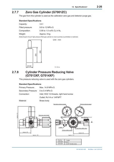
- Page 43: 2.7.6 Air Set 2-25 This set is use
- Page 47 and 48: 3-1 3. Installation This chapter de
- Page 49 and 50: 3-3 CAUTION • The dust filter is
- Page 51 and 52: 3-5 3.2 Installation of High Temper
- Page 53 and 54: 3-7 Table 3.2 Accessories for mount
- Page 55 and 56: 3-9 (1) Drill mounting holes throu
- Page 57 and 58: 3-11 3.5 Installation of ZR40H Auto
- Page 59 and 60: 3-13 3.6 Installation of the Case A
- Page 61 and 62: EXA ZR402G 4. Piping 4-1 This chap
- Page 63 and 64: 4.1.2 Connection to the Calibration
- Page 65 and 66: EXA ZR402G 4-5 4.2 Piping for Syst
- Page 67 and 68: 4-7 Stop valve or Check valve Pipin
- Page 69 and 70: 4.3.1 Blow Back Piping 4-9 This pi
- Page 71 and 72: EXA ZR402G 4-11 CAUTION • As far
- Page 73 and 74: 5-1 5. Wiring In this Chapter, the
- Page 75 and 76: 5.1.2 Wiring 5-3 Connect the follo
- Page 77 and 78: 5.2 Wiring for Detector Output 5-5
- Page 79 and 80: 5.3 Wiring for Power to Detector He
- Page 81 and 82: 5.4 Wiring for Analog Output 5-9 T
- Page 83 and 84: 5-11 5.7 Wiring for ZR40H Automatic
- Page 85 and 86: 6-1 6. Components In this Chapter,
- Page 87 and 88: 6-3 6.2 ZR402G Converter Complete O
- Page 89 and 90: 7-1 7. Startup The following descri
- Page 91 and 92: 7.4 Touchpanel Switch Operations 7.
- Page 93 and 94: 7.4.3 Display Functions 7-5 Indivi
- Page 95 and 96:
7-7 7.5 Confirmation of Converter T
- Page 97 and 98:
7.9 Setting Display Item 7-9 This
- Page 99 and 100:
7.10 Checking Current Loop The set
- Page 101 and 102:
7.11.2 Checking Calibration Contact
- Page 103 and 104:
7-15 (2) Span gas concentration Wit
- Page 105 and 106:
7-17 (7) Follow the instructions in
- Page 107 and 108:
8. Detailed Data Setting 8-1 8.1 C
- Page 109 and 110:
8.2 Output Hold Setting 8-3 The
- Page 111 and 112:
8.2.4 Default Values 8-5 When the
- Page 113 and 114:
8-7 In the example in Figure 8.3, t
- Page 115 and 116:
8-9 8.4 Output Contact Setup 8.4.1
- Page 117 and 118:
8-11 Table 8.5 Output Contact Setti
- Page 119 and 120:
8-13 8.5 Input Contact Settings 8.5
- Page 121 and 122:
8-15 8.6 Other Settings 8.6.1 Setti
- Page 123 and 124:
8-17 For liquid fuel 3 Amount of wa
- Page 125 and 126:
8-19 Table 8.8 Fuel Data • For li
- Page 127 and 128:
8.6.4 Setting Purging 8-21 Purging
- Page 129 and 130:
9-1 9. Calibration 9.1 Calibration
- Page 131 and 132:
9.1.3 Compensation 9-3 The deviati
- Page 133 and 134:
9-5 9.2 Calibration Procedures NOTE
- Page 135 and 136:
9-7 9.2.1.5 Setting Calibration Tim
- Page 137 and 138:
9-9 9.2.3 Calibration NOTE 1) Perfo
- Page 139 and 140:
10. Other Functions 10-1 10.1 Disp
- Page 141 and 142:
10-3 10.1.1.6 Cell Voltage The cell
- Page 143 and 144:
10.1.2 Trend Graph 10-5 Press the
- Page 145 and 146:
10.1.3 Auto-Return Time 10-7 On th
- Page 147 and 148:
10.2.1.2 Operation of Blow back 10
- Page 149 and 150:
10.3 Parameter Initialization 10-1
- Page 151 and 152:
10-13 Table 10.5 Initialization Ite
- Page 153 and 154:
10.4 Reset 10-15 Resetting enables
- Page 155 and 156:
10.5.2 Installing Gas Cylinders 10
- Page 157 and 158:
10-19 (1) Use the needle of the zer
- Page 159 and 160:
10.6.3 Operating the Zero Gas Flow
- Page 161 and 162:
11-1 11. Inspection and Maintenance
- Page 163 and 164:
11-3 (5) Clean the sensor assembly,
- Page 165 and 166:
11-5 16 A 14 ‣ 14 10 11 12 ‣ 14
- Page 167 and 168:
11-7 Part No. (7) K9470BJ Metal O-r
- Page 169 and 170:
To replace the fuse, follow these s
- Page 171 and 172:
12. Troubleshooting 12-1 This chap
- Page 173 and 174:
12.1.2.2 Error2: Heater Temperature
- Page 175 and 176:
12-5 12.2 Displays and Remedies Whe
- Page 177 and 178:
12-7 (4) Check whether the deterior
- Page 179 and 180:
12-9 (3) A failure of the cold junc
- Page 181 and 182:
12-11 12.3 Countermeasures When Mea
- Page 183 and 184:
Customer Maintenance Parts List Mod
- Page 185 and 186:
Customer Maintenance Parts List Mod
- Page 187 and 188:
Customer Maintenance Parts List E70
- Page 189 and 190:
Revision Information i Title : Mod
- Page 191 and 192:
User’s Manual Model ZR22G, ZR402G
- Page 193 and 194:
2.3.2 ZO21P High Temperature Probe
- Page 195 and 196:
2.4 ZR402G Separate type Converter
- Page 197 and 198:
5-2 WARNING Cables that withstand t
- Page 199 and 200:
5.2.2 Connection to the Detector 5
- Page 201 and 202:
5-8 Notice when closing the cover o
- Page 203 and 204:
Customer Maintenance Parts List Mod
- Page 205 and 206:
Customer Maintenance Parts List Mod