User's Manual for ZR22G, ZR402G - Yokogawa
User's Manual for ZR22G, ZR402G - Yokogawa
User's Manual for ZR22G, ZR402G - Yokogawa

You also want an ePaper? Increase the reach of your titles
YUMPU automatically turns print PDFs into web optimized ePapers that Google loves.
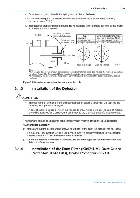
(1) Do not mount the probe with the tip higher than the probe base.<br />
3-2<br />
(2) If the probe length is 2.5 meters or more, the detector should be mounted vertically<br />
(no more than a 5° tilt).<br />
(3) The detector probe should be mounted at right angles to the sample gas flow or the probe<br />
tip should point downstream.<br />
100 mm<br />
(vertical)<br />
Bounds of the probe<br />
insertion hole location<br />
Flange matches<br />
the detector size<br />
*1<br />
Type<br />
Outside diameter of detector<br />
Standard<br />
50.8 mm in diameter (Note)<br />
With dust filter 51 mm in diameter (Note)<br />
With probe protector 60.5 mm in diameter (Note)<br />
*1<br />
(horizontal)<br />
Note<br />
100 mm<br />
Four-hole flange<br />
Eight-hole flange<br />
F3-1E.ai<br />
(Note)<br />
When using the detector with pressure compensation, ensure that the flange gasket does not block the reference gas outlet on<br />
the detector flange. If the flange gasket blocks the outlet, the detector cannot per<strong>for</strong>m pressure compensation.<br />
Where necessary, make a notch in the flange gasket. Confirm the outside dimensions of the detector in Section 2.2 be<strong>for</strong>e<br />
installation.<br />
Figure 3.1 illustrates an example of the probe insertion hole.<br />
3.1.3 Installation of the Detector<br />
CAUTION<br />
• The cell (sensor) at the tip of the detector is made of ceramic (zirconia). Do not drop the<br />
detector, as impact will damage it.<br />
• A gasket should be used between the flanges to prevent gas leakage. The gasket material<br />
should be heatproof and corrosion-proof, suited to the characteristics of the sample gas.<br />
The following should be taken into consideration when mounting the general use detector:<br />
<br />
(1) Make sure that the cell mounting screws (four bolts) at the tip of the detector are not loose.<br />
If a dust filter (see Section 2.7.1) is used, make sure it is properly attached to the detector.<br />
Refer to Section 3.1.4 <strong>for</strong> installation of the dust filter.<br />
(2) Where the detector is mounted horizontally, the calibration gas inlet and the reference gas<br />
inlet should face downward.<br />
3.1.4 Installation of the Dust Filter (K9471UA), Dust Guard<br />
Protector (K9471UC), Probe Protector ZO21R<br />
IM 11M12A01-02E<br />
8th Edition : Jan.13,2012-00