AN068 - Design Steps and Results for Changing PCB Layer Thickness
AN068 - Design Steps and Results for Changing PCB Layer Thickness
AN068 - Design Steps and Results for Changing PCB Layer Thickness

You also want an ePaper? Increase the reach of your titles
YUMPU automatically turns print PDFs into web optimized ePapers that Google loves.
Application Note <strong>AN068</strong><br />
<strong>AN068</strong><br />
<strong>Design</strong> <strong>Steps</strong> <strong>and</strong> <strong>Results</strong> <strong>for</strong> <strong>Changing</strong> <strong>PCB</strong> layer<br />
thickness <strong>for</strong> Low Power Wireless Reference EVMs<br />
By Rea Schmid<br />
Keywords<br />
• Board Stacking <strong>for</strong> RF <strong>Design</strong><br />
• VSWR changes with Stacking<br />
• B<strong>and</strong>width <strong>and</strong> <strong>Layer</strong> Stacking<br />
• <strong>PCB</strong> <strong>for</strong> CC25xx Devices<br />
• 062 Mil <strong>Layer</strong> Stacking<br />
• FR4 Dielectric Material<br />
• EVM <strong>for</strong> Low Power Wireless<br />
• Board per<strong>for</strong>mance <strong>for</strong> RF <strong>Design</strong><br />
• Matching networks <strong>for</strong> <strong>PCB</strong> Boards<br />
• Discrete Component Balun <strong>Design</strong><br />
• Matching antenna<br />
• RF Filter <strong>Design</strong><br />
Introduction<br />
Texas Instruments provides Evaluation<br />
Modules (EVMs) <strong>for</strong> easy characterization<br />
of the Low Power Wireless (LPW)<br />
products. They provide a means to<br />
underst<strong>and</strong> the device’s operation, <strong>and</strong><br />
decrease the product development time.<br />
Often a customer will copy the hardware<br />
layout, <strong>and</strong> then make small changes that<br />
can cause the per<strong>for</strong>mance to change.<br />
The most common changes are modifying<br />
the layer board stacking or changing<br />
component placement. Each of these will<br />
mistune the matching or filter networks<br />
<strong>and</strong> even the antenna, reducing the<br />
system per<strong>for</strong>mance.<br />
Learning how the <strong>PCB</strong> layer stack causes<br />
a mismatch at the RF connection between<br />
the RF output pins to the antenna is the<br />
scope of this application note.<br />
TI’s Evaluation Boards are designed to be<br />
flexible <strong>and</strong> easy to use. The boards are<br />
designed to accommodate a range of<br />
VSWR to make them acceptable <strong>for</strong> wide<br />
range of use. All EVMs are designed <strong>for</strong> a<br />
maximum VSWR of 2, which translates to<br />
a minimum return loss (RL) of -9.5dB<br />
derived from the S11 s-parameter.<br />
Each TI device specifies a typical load<br />
found in the data sheet that is used to<br />
match <strong>and</strong> complete the maximum power<br />
transfer. The spec is <strong>for</strong> a given<br />
frequency of operation. The number is<br />
used as the starting point <strong>for</strong> designing the<br />
interface to a selected antenna. For many<br />
applications the load is single ended; since<br />
most chips provide a differential<br />
input/output, the circuit often must include<br />
a translation to interface to a single-ended<br />
antenna. Typically these interfaces include<br />
three circuit blocks consisting of a balun, a<br />
filter/matching network, <strong>and</strong> finally a<br />
connection to the antenna, either through<br />
an SMA connector or directly connected.<br />
A note about the use of discrete<br />
components: values at 2.45GHz are often<br />
small with units on the order of pico-farads<br />
<strong>and</strong> nano-henries. There<strong>for</strong>e, the final<br />
solution per<strong>for</strong>mance is often sensitive to<br />
layout traces <strong>and</strong> pads.<br />
There are several methods used to design<br />
<strong>and</strong> select the circuit components <strong>and</strong><br />
trace lengths. The methods often used<br />
are Smith Charts, Simulation programs,<br />
Circuit Analysis, or copying <strong>and</strong> scaling<br />
existing designs. But at the higher<br />
frequencies one must recognize the use of<br />
tools greatly increases the accuracy of the<br />
final design.<br />
1<br />
SWRA236<br />
Page of 20
Application Note <strong>AN068</strong><br />
Because of the high frequencies <strong>and</strong> the<br />
fact we are using FR4 material, there are<br />
many additional factors to consider; FR4<br />
permittivity, stacking height, magnetic<br />
fields, trace thickness <strong>and</strong> solder mask.<br />
Not to mention it is difficult to make<br />
measurements at these frequencies<br />
without equipment like VNAs or TDRs.<br />
For this discussion we tried to isolate the<br />
effects of changing the stacking height to<br />
better underst<strong>and</strong> its impact upon the<br />
overall board’s per<strong>for</strong>mance as one makes<br />
this change. These results are included at<br />
the end of the application note.<br />
Keywords........................................................................................................................................................ 1<br />
Introduction .................................................................................................................................................... 1<br />
Abbrevations: ............................................................................................................................................. 3<br />
LPW Evaluation Boards ................................................................................................................................. 4<br />
Why RF designs change with Board <strong>Layer</strong> Stacking.................................................................................. 4<br />
Circuit Schematic of balun/matching Network. .......................................................................................... 6<br />
<strong>PCB</strong> Layout Techniques <strong>for</strong> Board Stacking Change..................................................................................... 6<br />
2-<strong>Layer</strong> <strong>Design</strong>s.......................................................................................................................................... 6<br />
<strong>PCB</strong> Traces <strong>and</strong> Transmission Lines .......................................................................................................... 7<br />
Determine the Source Impedance ............................................................................................................... 8<br />
Inductance from Vias.............................................................................................................................. 9<br />
VCO or Crystal Filter ............................................................................................................................... 10<br />
Figure 7, VCO crystal.............................................................................................................................. 10<br />
Current Loops <strong>and</strong> Decoupling................................................................................................................. 10<br />
Transmit & Receive Optimization ............................................................................................................ 11<br />
Sample <strong>Design</strong> <strong>for</strong> Compact <strong>Design</strong>......................................................................................................... 12<br />
Balun / Matching Network Measurements................................................................................................ 14<br />
Sensitivity Comparison............................................................................................................................. 15<br />
Power Output Comparison........................................................................................................................ 16<br />
Spectrum of Board Noise Sources............................................................................................................ 17<br />
Summary................................................................................................................................................... 18<br />
RF Layout Tips............................................................................................................................................. 18<br />
References .................................................................................................................................................... 19<br />
General references .................................................................................................................................... 19<br />
Document History......................................................................................................................................... 19<br />
Figure 2, Schematic of Original Layout 6<br />
Figure 3, 062 mil board layout 7<br />
Figure 4, Microstrip line definition 7<br />
Figure 5, Differential Conversion 9<br />
Figure 6, via inductance <strong>and</strong> Capacitance 9<br />
Figure 8, Placement of Decoupling Caps 11<br />
Figure 9, Single-ended model 12<br />
Figure 10, Differential Balun <strong>and</strong> Pi Filter 12<br />
Figure 11, Smith Chart Plot of Components Only 13<br />
Figure 12, Component Schematics only 13<br />
Figure 13, 031 mill stacking, Impedance of EVM at Antenna SMA 14<br />
Figure 14, 059 stacking height Impedance measured at SMA 15<br />
Figure 15, Schematic of <strong>PCB</strong> model 15<br />
Figure 16 Sensitivity Plot of 62mil (1.6mm) board 16<br />
Figure 17, Sensitivity Plot of 31mil (1.0mm) <strong>PCB</strong> 16<br />
Figure 18, Output Power Plot 1.6mm <strong>PCB</strong> 17<br />
Figure 19, Original Output Power Plot. 17<br />
2<br />
SWRA236<br />
Page of 20
Application Note <strong>AN068</strong><br />
Figure 20, Spectrum of CC2500 18<br />
Abbrevations:<br />
VNA - Vector Network Analyzer (test equipment)<br />
TDR - Time Domain Reflectometer (test equipment)<br />
TEM - Transverse Electro - Magnetic Mode<br />
FR4 - <strong>PCB</strong> board st<strong>and</strong>ard<br />
SMA - Coaxial <strong>PCB</strong> connector<br />
<strong>PCB</strong> - Printed Circuit Board<br />
LPW - Low Power Wireless<br />
EVM - Evaluation Module<br />
MM - mili-meters<br />
Mil - 1 thous<strong>and</strong> of an inch<br />
VCO - voltage control oscillator<br />
Balun - balance to unbalance trans<strong>for</strong>mer<br />
3<br />
SWRA236<br />
Page of 20
Application Note <strong>AN068</strong><br />
LPW Evaluation Boards<br />
A LPW evaluation board provides a simple evaluation unit to quickly underst<strong>and</strong> the technical<br />
operation of a Low Power Wireless device from Texas Instruments. As the board is a working<br />
solution to demonstrate both transmit / receive modes, customers can also evaluate a particular<br />
transmit/receive device. They can quickly modify a specific application to gather measurements<br />
related to their product design.<br />
TI’s LPW evaluation boards include the trace layout, component values, the use of FR4 board<br />
materials <strong>and</strong> board thickness to show typical per<strong>for</strong>mance <strong>for</strong> a device. The board serves also<br />
as a reference design as one makes changes to a prototype board. It also cuts development time<br />
<strong>and</strong> allows one to become familiar with the device without worrying about optimizing a RF prototype.<br />
A LPW EVM provides a reference design that is tested <strong>and</strong> measured following many of the same<br />
steps done in a design process as shown below. Using an evaluation unit is good practice <strong>and</strong> is<br />
an excellent reference to compare or copy in your final design. A TI evaluation unit along with<br />
development tools such as SmartRF plat<strong>for</strong>ms make it easier to complete a design with these<br />
devices. The various items verified during EVM development are:<br />
1. B<strong>and</strong>width Optimized <strong>for</strong> Channel Data Rates <strong>and</strong> Power<br />
2. Per<strong>for</strong>mance <strong>and</strong> Sensitivity Measurements<br />
3. Differential to Single-ended Conversion<br />
4. Matching to antenna Dipole, Micro-circuit or Chip<br />
5. Proper routing of Ground <strong>and</strong> Power Returns<br />
6. Low Electric Magnetic Emissions (EMI)<br />
7. Characterization Measurements<br />
8. Antenna Per<strong>for</strong>mance Measurements<br />
Although these parameters are tested on the evaluation unit, one must realize these tests are the<br />
results of the device, <strong>PCB</strong> board, <strong>and</strong> all circuit components. <strong>Changing</strong> a board means verifying<br />
items as shown above prior to final release. The local TI representatives can provide assistance<br />
or suggestions on tools or global st<strong>and</strong>ards when designing with TI wireless devices.<br />
For this app note a CC2500 is used, but this report pertains to all devices which require RF layout<br />
or board stacking changes. Keep in mind that different devices do have different output<br />
impedances <strong>and</strong>/or output stages. There<strong>for</strong>e the solutions might be slightly different <strong>for</strong> those<br />
devices, such as CC110x series.<br />
The stacking height that was chosen <strong>for</strong> the new evaluation unit using the CC2500 board is 62mil<br />
(1.6mm). (The reference design has 31 mil, or 0.8 mm, layer spacing.) All calculations were<br />
done in mils, but can easily be converted to meters by the following expression.<br />
1<br />
1 mil = ( inch)<br />
= 25.4µ<br />
m<br />
1000<br />
Why RF designs change with Board <strong>Layer</strong> Stacking<br />
4<br />
SWRA236<br />
Page of 20
Application Note <strong>AN068</strong><br />
When designing the balun <strong>and</strong> matching network <strong>for</strong> a RF device, the lessons to learn is the<br />
component values are small at 2.45GHz, <strong>and</strong> <strong>PCB</strong> traces affect the per<strong>for</strong>mance. As the<br />
component tolerances <strong>and</strong> component st<strong>and</strong>ard values prevent selection of the exact circuit<br />
values, the components can be combined with the board’s traces/pads inductance <strong>and</strong><br />
capacitance values to fine tune a network. Doing this requires fewer components <strong>and</strong> makes it<br />
easier to achieve VSWR closer to 1. This will work as long as one keeps the total length of<br />
traces less than ¼ wavelength, then the traces are treated as inductors.<br />
Because the component values are small at these frequencies, the trace <strong>and</strong> pad inductances<br />
<strong>and</strong> capacitances change with layer stack height. This is easily seen if you work with a micro-strip<br />
over a ground plane with air as one dielectric <strong>and</strong> the other a FR4 dielectric. The equation below<br />
shows the impedance change with width <strong>and</strong> height, <strong>and</strong> includes the dielectric correction <strong>for</strong> the<br />
FR4 <strong>PCB</strong> material. This equation below is used when the ratio of width to height is less than 1.<br />
Z<br />
o<br />
60<br />
eff<br />
8 ⋅ h<br />
⋅ln(<br />
w<br />
w<br />
+ )<br />
4 ⋅ h<br />
=<br />
ε<br />
⎥ ⎥⎥⎥ ⎦<br />
Where; h is the board stacking layer spacing<br />
w is the trace width<br />
ε eff is the dielectric correction <strong>for</strong> FR4 derived from free space dielectric permittivity<br />
Because we working with two different dielectrics, air <strong>and</strong> FR4, the correction factor <strong>for</strong> dielectric<br />
is;<br />
ε<br />
eff<br />
⎡<br />
ε<br />
⎢<br />
r<br />
+ 1 ε<br />
r<br />
−1<br />
= + ⋅ ⎢<br />
2 2 ⎢<br />
⎢<br />
⎣<br />
1<br />
12⋅<br />
h<br />
1+<br />
w<br />
⎛ ⎛ w ⎞⎞<br />
+ 0.04⎜1−<br />
⎜ ⎟⎟<br />
⎝ ⎝ h ⎠⎠<br />
Where ε<br />
r<br />
is the permittivity of the FR4 material.<br />
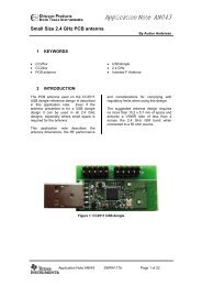
To better illustrate how the impedance changes with the width, height, <strong>and</strong> FR4 dielectric, a plot<br />
(Figure 1) included shows how much change takes place.<br />
Impedance change with stacking height<br />
2<br />
⎤<br />
Impedance Zo<br />
80<br />
75<br />
70<br />
65<br />
60<br />
55<br />
50<br />
45<br />
40<br />
35<br />
30<br />
59 mil stacking<br />
30 mil stacking<br />
2 2.05 2.1 2.15 2.2<br />
Permitivity Square Root e r<br />
Figure 1, Impedance Plot verses layer stacking height<br />
5<br />
SWRA236<br />
Page of 20
Application Note <strong>AN068</strong><br />
The permittivity is plotted in square root since the equations uses the square root of the air<br />
permittivity to derive the correct impedance along with the width to height ratio.<br />
Since the areas of the traces are in order of 8 to 12 mils the traces are primarily inductive with a<br />
small distributed capacitance. What is important to point out is that <strong>for</strong> a given stacking height the<br />
variation of permittivity only changes the impedance slightly. There<strong>for</strong>e, it can be seen that board<br />
trace impedance is somewhat constant over manufacturing processes.<br />
Circuit Schematic of balun/matching Network.<br />
The schematic, Figure 2, shows the CC2500 balun, matching filter, <strong>and</strong> a 50 Ω trace to an SMA.<br />
The schematic shows the values used on this board, <strong>and</strong> how small the component values are<br />
when working at 2.45GHz.<br />
Figure 2, Schematic of Original Layout<br />
For a network that is well matched (VSWR=1) the values will be an exact match. But as will be<br />
shown in this example the values selected on the 1mm (31mil) board are within the VSWR=2<br />
circle, though slightly mismatched.<br />
<strong>PCB</strong> Layout Techniques <strong>for</strong> Board Stacking Change<br />
2-<strong>Layer</strong> <strong>Design</strong>s<br />
2-layer designs typically require a little more care with the <strong>PCB</strong> routing than designs with designs<br />
with dedicated power <strong>and</strong> ground planes, but can be successfully implemented, as shown in<br />
Figure 3 (layout of the new 62 mil board); the original 30mil (0.8mm) is also on a 2-layer board.<br />
Note that the power supply trace on the 062mil board below shows the component side trace is<br />
made thick so as to present as low as impedance as possible. Large areas of ground on this side<br />
of the board provide a low impedance path <strong>for</strong> decoupling. Whenever possible include a bottom<br />
(copper) side of the board to allow <strong>for</strong> a solid plane under the RF circuitry. This design shows a<br />
VSWR of
Application Note <strong>AN068</strong><br />
Figure 3, 062 mil board layout<br />
A 2-layer <strong>PCB</strong> will be cheaper to manufacture than a 4-layer <strong>PCB</strong>. This paper shows that<br />
microstrip or stripline transmission lines can be implemented on boards with layer spacings<br />
exceeding 0.8mm - 1.00mm (0.031” - 0.039”) without an issue. The balun <strong>and</strong> filter trace widths<br />
<strong>for</strong> the transmission line traces are kept short <strong>and</strong> become part of the tuning network with the final<br />
trace to the SMA set <strong>for</strong> a 50 Ω impedance to match the antenna input. Note what is not shown<br />
are the vias shorting the top (copper) ground to the bottom ground plane. These are necessary to<br />
<strong>for</strong>ce FR4 board TEM resonance to a higher frequency than the CC2500’s 2.45GHz frequencies.<br />
<strong>PCB</strong> Traces <strong>and</strong> Transmission Lines<br />
Figure 4 illustrates an example of a <strong>PCB</strong> trace on the component or top side of the board that is<br />
isolated by the <strong>PCB</strong> dielectric material (typically FR4) from the ground plane layer. From<br />
knowledge of the physical properties of the <strong>PCB</strong> it is possible to construct a transmission line<br />
trace with the desired characteristic impedance.<br />
h<br />
ε r<br />
w<br />
l = length of trace (inches)<br />
w = width of trace (mils)<br />
h = height of trace (mils)<br />
t = thickness of trace (mils)<br />
ε r = <strong>PCB</strong> Permittivity (FR-4 ≈<br />
4.5)<br />
2 ⋅ l<br />
w + h<br />
L(<br />
nH)<br />
= 5.08 ⋅ l ⋅ ln(( ) + 0.5 + 0. 2235⋅<br />
w + h<br />
l<br />
t<br />
2<br />
CL = Z o<br />
0<br />
C(pF) ≈<br />
Figure 4, Microstrip line definition<br />
.67 ( + 1.41)<br />
ln<br />
5.98h<br />
0.8w<br />
+ t<br />
10 mil trace on 0.031”or 0.059” thick <strong>PCB</strong> (FR4) has:<br />
≈ 1.539nH <strong>for</strong> 100mil length<br />
≈ 1.35pF / inch length<br />
⎛<br />
⎜<br />
⎝<br />
ε eff<br />
⎞<br />
⎟<br />
⎠<br />
Z o is the characteristic<br />
impedances<br />
7<br />
SWRA236<br />
Page of 20
Application Note <strong>AN068</strong><br />
To calculate the required width of the <strong>PCB</strong> trace, W, it is first necessary to calculate the effective<br />
dielectric constant, ε eff , 1 The effective dielectric constant is required because part of the field<br />
generated by the conductor will exist in air ( ε<br />
r<br />
= 1) <strong>and</strong> part in the dielectric material. Assuming<br />
that the thickness of the trace, T, is small compared to the height of the dielectric (T/H < 0.005),<br />
then ε eff an be calculated using the following <strong>for</strong>mula:<br />
w<br />
h<br />
< 1<br />
Z<br />
o<br />
60<br />
eff<br />
8 ⋅ h<br />
⋅ln(<br />
w<br />
+<br />
w<br />
)<br />
4 ⋅ h<br />
e<br />
eff<br />
⎡<br />
ε<br />
⎢<br />
r<br />
+ 1 ε<br />
r<br />
− 1<br />
= + ⋅ ⎢<br />
2 2 ⎢<br />
⎢<br />
⎣<br />
1<br />
12 ⋅ h<br />
1 +<br />
w<br />
⎛ ⎛ w ⎞ ⎞<br />
+ 0.04⎜1<br />
− ⎜ ⎟ ⎟<br />
⎝ ⎝ h ⎠ ⎠<br />
⎤<br />
⎥<br />
⎥<br />
⎥<br />
⎥<br />
⎦<br />
2<br />
w<br />
h<br />
> 1<br />
Z<br />
o<br />
=<br />
e<br />
eff<br />
⎛w<br />
⋅⎜<br />
⎝ h<br />
=<br />
ε<br />
w<br />
120 ⋅π<br />
w<br />
+ 1.393 + 0.667 ⋅ln(<br />
h<br />
⎞<br />
+ 1.444⎟<br />
⎠<br />
e<br />
eff<br />
ε<br />
r<br />
+ 1 ε<br />
r<br />
−1<br />
= + ⋅<br />
2 2<br />
1<br />
12 ⋅h<br />
1+<br />
Determine the Source Impedance<br />
The equivalent circuit of the RF output is shown in Figure 5 below. The differential circuit is hard<br />
to plot on a Smith Chart, so converting to a single-ended equivalent output source makes it easier<br />
to use a Smith Chart <strong>and</strong> VNA when designing a balun.<br />
1 I. J. Bahl <strong>and</strong> D. K. Trvedi, “A <strong>Design</strong>er’s Guide to Microstrip Line”, Microwaves, May 1977<br />
8<br />
SWRA236<br />
Page of 20
Application Note <strong>AN068</strong><br />
R diff<br />
2<br />
2 ⋅C diff<br />
2 ⋅C diff<br />
R diff<br />
2<br />
Figure 5, Differential Conversion<br />
From the data sheet parameter spec page the recommended load impedance is given as<br />
80+j74Ω. The conjugate of this number Z=Z* is the source’s impedance which is 80-j74Ω. We<br />
normalize this signal by dividing by 50 Ω.<br />
80 − j74<br />
= 1.6 +<br />
50<br />
j1.48<br />
This conjugate (1.6 – j1.48) would be the differential impedance looking back into the plus <strong>and</strong><br />
minus pins of the device. The negative –j implies a capacitance reactance, which we can find at<br />
the frequency of 2.45GHz using the equation that X c is equal to j2πfC <strong>and</strong> Xc is 74 ohms.<br />
1 −15<br />
C diff<br />
= = 878.0X10<br />
2 πf 74<br />
Inductance from Vias<br />
Inductance in RF board design has the largest effect when changing the matching network, balun<br />
design <strong>and</strong> antenna loads. Single- <strong>and</strong> multi-layer boards use vias to connect from one layer or<br />
strip to another. The problem is of increased inductance <strong>and</strong> capacitance between those paths to<br />
return grounds or signal paths. A typical via that connects a top layer ground plane to a bottom<br />
ground plane results in a small inductance added between layers. This can be approximated by<br />
the following <strong>for</strong>mula in Figure 6.<br />
⎡ ⎛ 4h<br />
⎞ ⎤<br />
L(nH) = 2 ⋅ h⎢ln⎜<br />
⎟ + 1⎥<br />
⎣ ⎝ d ⎠ ⎦<br />
C(pF) =<br />
0.55<br />
d<br />
2<br />
ε<br />
r<br />
h d<br />
− d<br />
1<br />
1<br />
C ⋅L<br />
=<br />
2<br />
Z o<br />
h is thickness of <strong>PCB</strong><br />
ε r permittivity of FR4 board<br />
d 1 diameter of the pad surrounding via<br />
d 2 diameter of the pad connecting<br />
ground plane layers.<br />
Figure 6, via inductance <strong>and</strong> Capacitance<br />
9<br />
SWRA236<br />
Page of 20
Application Note <strong>AN068</strong><br />
For vias with no relief at the layer connections, d1 is zero, <strong>and</strong> the capacitance decreases.<br />
Typically <strong>for</strong> a 1.6mm thickness <strong>PCB</strong> material, a single via can add 1.2nH of inductance <strong>and</strong><br />
0.5pF of capacitance, depending upon the via’s dimensions <strong>and</strong> <strong>PCB</strong> dielectric material, although<br />
the effects can be minimized by ensuring that the inter-via spacing is between 1/10 - l/30<br />
wavelengths.<br />
Sometimes the knowledge of the physical properties of the <strong>PCB</strong> can be used to the advantage of<br />
the design engineer. For example, an inductance derived from a <strong>PCB</strong> trace will offer much greater<br />
repeatability than a commercially available component.<br />
VCO or Crystal Filter<br />
The external VCO crystal of the CC2500 consists of series external traces (that have inductance)<br />
<strong>and</strong> parallel capacitors across a differential input. Hence the <strong>PCB</strong> layout should endeavor to<br />
respect the symmetry of this port. This <strong>PCB</strong> trace line characteristics change with height <strong>and</strong> can<br />
cause changes to the oscillator’s frequency of operation. It’s important when minimizing the<br />
radiation from the VCO circuit to keep the traces as short as possible <strong>and</strong> to re-check the<br />
frequency of oscillation as the traces’ impedances can change the oscillator’s frequency; see<br />
Figure 7.<br />
For a 2-sided layout, maintaining a symmetrical <strong>PCB</strong> layout with respect to the VCO oscillator is<br />
recommended. Note that in the design illustrated here, the traces are kept as short as possible,<br />
<strong>and</strong> the entire circuit is enclosed within a ground or guard b<strong>and</strong>. This ground trace both minimizes<br />
radiation from the VCO as well as prevents noise from being injected directly into the VCO circuit<br />
traces.<br />
VCO oscillator<br />
Figure 7, VCO crystal<br />
To minimize the possibility of inductive cross coupling between the VCO <strong>and</strong> the transmitter <strong>and</strong><br />
receiver blocks, it is recommended that the VCO inductor be placed orthogonal to the balun<br />
inductors.<br />
Current Loops <strong>and</strong> Decoupling<br />
Minimize current loops on <strong>PCB</strong> layouts by placing decoupling capacitors close to the part’s power<br />
pin with minimum return paths to ground. In order to compensate <strong>for</strong> the added inductance of the<br />
vias, additional parallel vias help lower the decoupling caps’ ground returns by paralleling the<br />
inductance of the vias. In the circles of Figure 8, below, the decoupling caps are placed in close<br />
proximity to the power pins. Note these caps are C3, C4, C6 <strong>and</strong> C7 seen in Figure 8. Try to<br />
avoid capacitive coupling by ensuring that each circuit block or power port has its own decoupling<br />
10<br />
SWRA236<br />
Page of 20
Application Note <strong>AN068</strong><br />
capacitor of value suggested in the data sheet. As a rule of thumb, components should not share<br />
vias. An additional 40 pF was added to this design to lower the analog spurs seen in the<br />
continuous output power spectrum after the stacking height was changed.<br />
VDD<br />
FB1<br />
P600R<br />
C16<br />
1 2<br />
1uF<br />
C3<br />
C1<br />
220pF<br />
C6<br />
220pF<br />
C2<br />
.1uF<br />
C5<br />
.1uF<br />
1<br />
2<br />
3<br />
6<br />
7<br />
17<br />
20<br />
SCLK<br />
SO(GDO1)<br />
GDO2<br />
GDO0<br />
CSn<br />
RBIAS<br />
SI<br />
DVDD 4<br />
5<br />
DCOUPL<br />
DGUARD 18<br />
AVDD 9<br />
AVDD 11<br />
GND(PAD)<br />
GND<br />
GND<br />
0<br />
.1uF<br />
C4<br />
.1uF<br />
C7<br />
220pF<br />
AVDD 14<br />
AVDD 15<br />
U1<br />
RF_P<br />
RF_N<br />
XOSC_Q1<br />
XOSC_Q2<br />
12<br />
13<br />
8<br />
10<br />
CC2500<br />
16<br />
19<br />
Placement of Decoupling Caps<br />
Figure 8,<br />
Transmit & Receive Optimization<br />
The Transmit & Receive matching serves two functions; first, to per<strong>for</strong>m a differential to singleended<br />
conversion, <strong>and</strong> secondly to attenuate the level of harmonic products generated due to<br />
circuit non-linearities. The easiest method to design the transmitter <strong>and</strong> receiver matching network<br />
is to use the single-ended source path to derive a matched impedance network. This network is<br />
illustrated below with the dc blocking cap, balun, <strong>and</strong> pi-matching filter calculated based upon singleended<br />
system; see Figure 9.<br />
11<br />
SWRA236<br />
Page of 20
Application Note <strong>AN068</strong><br />
Figure 9, Single-ended model<br />
Once L1 <strong>and</strong> C1 are found, then the PI-Network <strong>for</strong> the filter is designed to match the impedance<br />
connected to the SMA, which is generally 50Ω. Once this is done, the values of the balun are<br />
divided by two <strong>and</strong> become the conjugate to create 180 degree phase to make a balun. This is<br />
shown below in Figure 10.<br />
Figure 10, Differential Balun <strong>and</strong> Pi Filter<br />
The matching network is comprised of the following stages:<br />
• L1, C1: Together with <strong>PCB</strong> traces <strong>and</strong> device (packaging) parasitic components <strong>for</strong>ms a resonant<br />
load at the required output frequency.<br />
• The L/2, 2xC's: Are the values needed <strong>for</strong> a differential balun.<br />
• C provides a DC blocking from the RF Output stage.<br />
• C2, C3, L2: Form a PI low-pass harmonic filter.<br />
Note that these values were optimized on the reference design <strong>PCB</strong> <strong>and</strong> will probably not be the<br />
correct values <strong>for</strong> a different <strong>PCB</strong> stacking or layout.<br />
Sample <strong>Design</strong> <strong>for</strong> Compact <strong>Design</strong><br />
First all the impedances are normalized to 50 ohms. Use 2.45GHz, the center of the frequencies <strong>for</strong><br />
the device, as the operating frequency. A simple design procedure can be followed in the outlined<br />
below:<br />
1. Starting at the antenna port (which is assumed to be our 50 ohm reference point) design the pisection<br />
harmonic trap <strong>and</strong> plot on the Smith Chart, as represented in Figure 11, below.<br />
2. Add the series DC block <strong>and</strong> impedance trans<strong>for</strong>mation provided by the series inductor so that the<br />
impedance is trans<strong>for</strong>med from nominally 50 ohms <strong>and</strong> so that it lies on the same arc as the required<br />
load impedance, as illustrated in Figure 11.<br />
3. Finally, design the tuned load to present the optimum impedance to the transmitter stage. From<br />
Figure 15, it can be observed that the overall Q of the matching network is less than 1.0.<br />
12<br />
SWRA236<br />
Page of 20
Application Note <strong>AN068</strong><br />
4. Point 5 <strong>and</strong> 6 shows adding the balun values.<br />
5. The network can be implemented on stage by stage <strong>PCB</strong>2, enabling the engineer to check the<br />
theoretical results against those of the practical implementation.<br />
Below is a Smith Chart plot of just the component values. As can be seen, this by itself does not<br />
provide the correct load <strong>for</strong> the CC2500 device. Adding the component values <strong>for</strong> the traces<br />
alters the impedance matching network to provide the correct match from the output of the device<br />
to the 50Ω load.<br />
Figure 11, Smith Chart Plot of Components Only<br />
DP-Nr. 1(50.0 + j0.0)Ohm Q = 0.0 2.450 GHz<br />
DP-Nr. 2(21.4 - j24.7)Ohm Q = 1.2 2.450 GHz<br />
DP-Nr. 3(21.4 - j5.7)Ohm Q = 0.3 2.450 GHz<br />
DP-Nr. 4(12.7 - j11.4)Ohm Q = 0.9 2.450 GHz<br />
DP-Nr. 5(12.7 + j26.3)Ohm Q = 2.1 2.450 GHz<br />
DP-Nr. 6(67.1 + j0.0)Ohm Q = 0.0 2.450 GHz<br />
Figure 12, Component Schematics only<br />
13<br />
SWRA236<br />
Page of 20
Application Note <strong>AN068</strong><br />
This shows the source to be 1.34+j0 shown in Figure 12 <strong>and</strong> doesn’t agree with the original<br />
source impedance of 1.6+j1.48. There<strong>for</strong>e to plot the correct match, include the traces’<br />
inductances to achieve a lower VSWR number.<br />
Balun / Matching Network Measurements<br />
As we design the balun <strong>and</strong> matching network it is important to match the antenna’s feed line. It<br />
is a good idea to check that we accomplished this by observing how close to 50+j0 the system<br />
looks at the SMA while the chip is set to receive mode. Connecting a Vector Network Analyzer<br />
into S11 mode <strong>and</strong> calibrated <strong>for</strong> open, short <strong>and</strong> 50 ohm at connection of the SMA allows one to<br />
measure the input impedance <strong>and</strong> return loss. Place the CC2500 device in receive mode <strong>and</strong><br />
lower the VNA power output to -30 or -40dB so not to saturate the LNA. From the Smith Chart,<br />
Figure 13 & 14 the impedance is shown as viewed from the antenna.<br />
The target value is 50 +j0, creating a perfect match to the antenna with 50Ω at 2.45GHz is shown<br />
in Figure 14. The original 30mil (0.8mm) board showed an impedance of 41.21+j11 <strong>and</strong> is well<br />
within VSWR circle of 2. But since this is lower in value the power transmitted to the antenna is<br />
slightly low due to the reflected voltage from the mismatch.<br />
Figure 13, 031 mill stacking, Impedance of EVM at Antenna SMA<br />
14<br />
SWRA236<br />
Page of 20
Application Note <strong>AN068</strong><br />
Figure 14, 059 stacking height Impedance measured at SMA<br />
The closer the match is to 50+j0, the better the efficiency between the SMA <strong>and</strong> the selected<br />
antenna.<br />
Sometimes the quickest method to use is a good 3-D <strong>PCB</strong> simulator. Below shows the schematic<br />
<strong>and</strong> elements using Advanced <strong>Design</strong> System from Agilent to per<strong>for</strong>m the simulations. This<br />
method provides simulation files <strong>and</strong> the ability to check the final design’s S21 as well as S11.<br />
Metal-1<br />
Dielectric-1<br />
Metal-2<br />
Metal-i : T[i], COND[i], TYPE[i]<br />
Dielectric-i : ER[i], H[i], TAND[i]<br />
MLSUBSTRATE2<br />
Subst1<br />
Er=4.7<br />
H=59 mil<br />
TanD=0.002<br />
T[1]=1.4 mil<br />
Cond[1]=4.1E7<br />
T[2]=1.4 mil<br />
Cond[2]=4.1E7<br />
<strong>Layer</strong>Type[1]=signal<br />
<strong>Layer</strong>Type[2]=ground<br />
muRata<br />
MURATAInclude<br />
muRata<br />
Disp<br />
Temp<br />
DisplayTemplate<br />
disptemp1<br />
"S_Params_Quad_dB_Smith"<br />
LQG15<br />
L1<br />
Value="1.2[nH]"<br />
S-PARAMETERS<br />
S_Param<br />
SP1<br />
Start=1.0 GHz<br />
Stop=10.0 GHz<br />
Step=0.1 GHz<br />
GRM15<br />
C6<br />
Value="1.8[pF]"<br />
Port<br />
P1<br />
Num=1<br />
ML1CTL_C<br />
TL1<br />
Subst="Subst1"<br />
Length=38.2 mil<br />
W=10.0 mil<br />
GRM15<br />
C8<br />
Value="100[pF]"<br />
ML1CTL_C<br />
TL3<br />
Subst="Subst1"<br />
Length=35.5 mil<br />
W=10.0 mil<br />
ML1CTL_C<br />
TL5<br />
Subst="Subst1"<br />
Length=35.5 mil<br />
W=10.0 mil<br />
GRM15<br />
C4<br />
Value="1[pF]"<br />
MCURVE2<br />
Curve1<br />
Subst="Subst1"<br />
W=30 mil<br />
Angle=90<br />
Radius=30 mil<br />
Nmode=2<br />
ML1CTL_C<br />
TL6<br />
Subst="Subst1"<br />
Length=35.5 mil<br />
W=10.0 mil<br />
LQG15<br />
L3<br />
Value="1.2[nH]"<br />
ML1CTL_C<br />
TL8<br />
Subst="Subst1"<br />
Length=35.0 mil<br />
W=10.0 mil<br />
ML1CTL_C<br />
TL7<br />
Subst="Subst1"<br />
Length=195 mil<br />
W=55 mil<br />
Port<br />
P2<br />
Num=2<br />
GRM15<br />
Port<br />
P3<br />
Num=3<br />
ML1CTL_C<br />
TL2<br />
Subst="Subst1"<br />
Length=38.2 mil<br />
W=10.0 mil<br />
GRM15<br />
C2<br />
Value="100[pF]"<br />
ML1CTL_C<br />
TL4<br />
Subst="Subst1"<br />
Length=35.5 mil<br />
W=10.0 mil<br />
GRM15<br />
C9<br />
Value="1[pF]"<br />
LQG15<br />
L2<br />
Value="1.2[nH]"<br />
MCURVE2<br />
Curve2<br />
Subst="Subst1"<br />
W=30 mil<br />
Angle=90<br />
Radius=30 mil<br />
Nmode=2<br />
C5<br />
Value="1.5[pF]"<br />
Figure 15, Schematic of <strong>PCB</strong> model<br />
The component values in this simulation were from Murata but equivalent values from Pansonic<br />
<strong>and</strong> other vendors will work. The component values used in s-parameter simulation were<br />
supplied by the component manufacturers. Selecting the correct types of components requires<br />
careful considerations of the devices’ self-resonances <strong>and</strong> package parasitics, both of which will<br />
change the per<strong>for</strong>mance.<br />
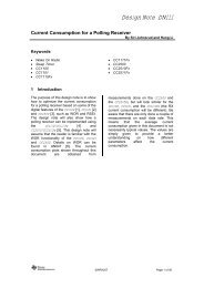
Sensitivity Comparison<br />
The receiver sensitivity is a measurement of the receiver’s input packet error rate. Since noise is<br />
measured in dB or power the noise floor <strong>for</strong> the board should be at least -3dB or lower than the<br />
input Noise Figure of the receiver. For 2-layer boards reducing the noise is accomplished by<br />
adding ground planes on top <strong>and</strong> bottom of the board. The plot in Figure 18 <strong>and</strong> 19 show the<br />
per<strong>for</strong>mance improvement over the original board with both the stacking <strong>and</strong> rules followed in this<br />
discussion to improve the per<strong>for</strong>mance.<br />
15<br />
SWRA236<br />
Page of 20
Application Note <strong>AN068</strong><br />
062 Mil EVM CC2500<br />
-82<br />
-83<br />
-84<br />
250Kbytes / sec data rate<br />
typical should be -89dBM @room temp. (3.0V) boards averaged -89.67<br />
-85<br />
Sensitivity (dB)<br />
-86<br />
-87<br />
-88<br />
-89<br />
-90<br />
-91<br />
-92<br />
-40 -20 0 20 40 60 80<br />
Temperature deg C<br />
1.8 Volts 3.6 volts Max 3.6 Min 1.8<br />
Figure 16 Sensitivity Plot of 62mil (1.6mm) board<br />
Note the variation of packet errors was reduced on this new board layout as shown in Figure<br />
Figure 16 compared to Figure 17, 31mil (1mm board). Across temperature the 31mil (1 mm)<br />
board had 4 dB variations in temperature <strong>and</strong> voltage while the 62mil (1.6mm) board shows 2.2<br />
dB.<br />
Sensitivity@2440 MHz<br />
Average data<br />
Temperature [°C]<br />
-40 25 85<br />
1.8 -90.3 -89.4 -87.1<br />
VDD [V] 3 -88.5 -89.0 -86.3<br />
3.6 -87.7 -88.2 -85.8<br />
Minimum data Temperature [°C]<br />
-40 25 85<br />
1.8 -91.7 -90.9 -88.3<br />
VDD [V] 3 -90.5 -90.3 -87.7<br />
3.6 -89.9 -89.5 -87.5<br />
Maximum data Temperature [°C]<br />
-40 25 85<br />
1.8 -89.7 -88.5 -86.5<br />
VDD [V] 3 -87.7 -87.5 -84.1<br />
3.6 -84.7 -86.7 -83.5<br />
St<strong>and</strong>ard deviation Temperature [°C]<br />
-40 25 85<br />
1.8 0.8 0.9 0.7<br />
VDD [V] 3 1.2 1.1 1.5<br />
3.6 2.4 1.1 1.5<br />
Power [dBm]<br />
-75.0<br />
-77.0<br />
-79.0<br />
-81.0<br />
-83.0<br />
-85.0<br />
-87.0<br />
-89.0<br />
-91.0<br />
-93.0<br />
-95.0<br />
Sensitivity@2440 MHz<br />
-40 25 85<br />
Temperature [°C]<br />
Figure 17, Sensitivity Plot of 31mil (1.0mm) <strong>PCB</strong><br />
Max data<br />
Avg 1.8V<br />
Avg 3V<br />
Avg 3.6V<br />
Min data<br />
Power Output Comparison<br />
16<br />
SWRA236<br />
Page of 20
Application Note <strong>AN068</strong><br />
Plotting the output power Figure 18 as measured at the SMA (antenna port) was compared to the<br />
31mil (1.0mm) <strong>PCB</strong> board. The power had a less variation over the total channels viewed.<br />
Worst case deviation was .5 dB compared to the original which has closer to a 1dB variation.<br />
Output Power vs. Freq (25 C, 3.0V<br />
2.0<br />
1.5<br />
1.0<br />
P o w e r ( d B m )<br />
0.5<br />
0.0<br />
Min<br />
Avg<br />
Max<br />
-0.5<br />
-1.0<br />
2 390<br />
2 400<br />
2 410<br />
2 420<br />
2 430<br />
2 440<br />
2450<br />
2460<br />
2470<br />
2480<br />
2490<br />
Freq (MHz)<br />
Figure 18, Output Power Plot 1.6mm <strong>PCB</strong><br />
Output Power vs Frequency (25°C, 3.0V, 5 samples)<br />
2.0<br />
1.5<br />
P o w e r [ d B m ]<br />
1.0<br />
0.5<br />
0.0<br />
Min<br />
Avg<br />
Max<br />
-0.5<br />
-1.0<br />
24 00<br />
24 05<br />
24 10<br />
24 15<br />
24 20<br />
24 25<br />
24 30<br />
24 35<br />
24 40<br />
Freq [MHz]<br />
24 4 5<br />
24 50<br />
24 55<br />
24 60<br />
24 65<br />
24 70<br />
24 75<br />
24 80<br />
Figure 19, Original Output Power Plot.<br />
Spectrum of Board Noise Sources<br />
Putting the channel into continuous transmit <strong>and</strong> looking at the spectrum of the signal <strong>and</strong> its<br />
noise spurs is used to control harmonics <strong>and</strong> noises that are too high <strong>for</strong> st<strong>and</strong>ards or low<br />
sensitivity readings. Placement of decoupling capacitors <strong>and</strong> the values determine how well the<br />
noise spurs are controlled. Often it is best to use smaller package size capacitors like 0402 to<br />
reach a lower noise floor. Below is a spectrum of the original EVM at 31 mils <strong>and</strong> the new board<br />
17<br />
SWRA236<br />
Page of 20
Application Note <strong>AN068</strong><br />
at 62 mils showed identical results. Because the layer spacing was increased, a 47 pf capacitor<br />
was added to the digital lines to lower harmonics in the signal b<strong>and</strong>. Of course a better<br />
measurement would be phase noise density of the power spectrum. This plot was not included<br />
but is often found in the device data sheet.<br />
Marker 1 [T1] RBW 3 kHz RF Att 10 dB<br />
Ref Lvl -14.82 dBm VBW 3 kHz<br />
-20 dBm 2.43296593 GHz<br />
1<br />
SWT 70 s Unit dBm<br />
-20<br />
A<br />
-30<br />
-40<br />
-50<br />
1AP<br />
-60<br />
-70<br />
-80<br />
-90<br />
-100<br />
-110<br />
-120<br />
Center 2.432965932 GHz<br />
Date: 6.JUL.2008 21:12:21<br />
25 MHz/<br />
Span 250 MHz<br />
Figure 20, Spectrum of CC2500<br />
Summary<br />
The data from the 62mil (1.6mm) EVM showed equivalent per<strong>for</strong>mance to the original 31mil<br />
(0.8mm) EVM over all corners of operation temperature <strong>and</strong> voltage. Although a small sample of<br />
parts (10 boards) were used to compare the results, the new board indicates a closer match <strong>and</strong><br />
the inclusion of the trace lengths in the balun/matching analysis improves the per<strong>for</strong>mance.<br />
Controlling the number of vias used in the digital paths reduce harmonics that might create<br />
current loops in the RF signal path.<br />
The original board S11 matching was just inside a VSWR of 2. Improved matching (shown in the<br />
impedance plots as the 2.45GHz point moving inside a smaller VSWR circle) resulted from<br />
stacking height change <strong>and</strong> demonstrated improved per<strong>for</strong>mance. This was seen in the<br />
sensitivity <strong>and</strong> power variation measurements.<br />
Controlling trace placement, widths, <strong>and</strong> ground all influence EMI on the boards, noise currents,<br />
<strong>and</strong> loop currents. As one might place components close together one should not place device<br />
closer than 20 mils <strong>for</strong> good isolation or low RF leakage. Gerber files found at the TI web site<br />
CC2500 product’s folder under CC2500_REFDES_062 provide the reference board layout <strong>for</strong><br />
copying or further review.<br />
RF Layout Tips<br />
1. Adapt trace widths <strong>for</strong> same characteristic impedance transmission of previous lines when changing the<br />
stacking height of the FR4 <strong>PCB</strong>.<br />
2. For a given stacking height the variation of permittivity only changes the impedance slightly<br />
3. Whenever possible include a bottom (copper) side of the board to allow <strong>for</strong> a solid ground plane under<br />
the RF circuitry<br />
18<br />
SWRA236<br />
Page of 20
Application Note <strong>AN068</strong><br />
4. Try to avoid using vias in the RF path <strong>and</strong> is they must be used take into account the added inductance<br />
<strong>and</strong> capacitance.<br />
5. Check the frequency of oscillation as the traces’ impedances can change the oscillator’s frequency - extra<br />
capacitance can detune the crystal <strong>and</strong> this means need to be compensated by changing the load capacitors<br />
accordingly.<br />
6. VCO oscillators should be placed orthogonal to the balun inductors<br />
7. Minimize current loops on <strong>PCB</strong> layouts by placing decoupling capacitors close to the part’s power pin<br />
with minimum return paths to ground<br />
8. Try to avoid capacitive coupling by ensuring that each circuit block or power port has its own decoupling<br />
capacitor of value suggested in the data sheet<br />
9. Avoid components returns through share ground vias.<br />
10. Select discrete components whose s-parameter show adequate linearity in frequency of interest.<br />
11. Keep trace lines short when possible, only use long lines as required <strong>for</strong> RF.<br />
References<br />
General references<br />
[1] Presentation “<strong>PCB</strong> Resonance Significance <strong>and</strong> Avoidance”, Lel<strong>and</strong> Swanson,<br />
TI, July 12, 2005<br />
[2] “Signal Integrity Simplified” by Dr. Eric Bogatin, IBN 0-13-066946-6.<br />
Document History<br />
Revision Date Description/Changes<br />
1.0 Initial release.<br />
19<br />
SWRA236<br />
Page of 20
IMPORTANT NOTICE<br />
Texas Instruments Incorporated <strong>and</strong> its subsidiaries (TI) reserve the right to make corrections, modifications, enhancements, improvements,<br />
<strong>and</strong> other changes to its products <strong>and</strong> services at any time <strong>and</strong> to discontinue any product or service without notice. Customers should<br />
obtain the latest relevant in<strong>for</strong>mation be<strong>for</strong>e placing orders <strong>and</strong> should verify that such in<strong>for</strong>mation is current <strong>and</strong> complete. All products are<br />
sold subject to TI’s terms <strong>and</strong> conditions of sale supplied at the time of order acknowledgment.<br />
TI warrants per<strong>for</strong>mance of its hardware products to the specifications applicable at the time of sale in accordance with TI’s st<strong>and</strong>ard<br />
warranty. Testing <strong>and</strong> other quality control techniques are used to the extent TI deems necessary to support this warranty. Except where<br />
m<strong>and</strong>ated by government requirements, testing of all parameters of each product is not necessarily per<strong>for</strong>med.<br />
TI assumes no liability <strong>for</strong> applications assistance or customer product design. Customers are responsible <strong>for</strong> their products <strong>and</strong><br />
applications using TI components. To minimize the risks associated with customer products <strong>and</strong> applications, customers should provide<br />
adequate design <strong>and</strong> operating safeguards.<br />
TI does not warrant or represent that any license, either express or implied, is granted under any TI patent right, copyright, mask work right,<br />
or other TI intellectual property right relating to any combination, machine, or process in which TI products or services are used. In<strong>for</strong>mation<br />
published by TI regarding third-party products or services does not constitute a license from TI to use such products or services or a<br />
warranty or endorsement thereof. Use of such in<strong>for</strong>mation may require a license from a third party under the patents or other intellectual<br />
property of the third party, or a license from TI under the patents or other intellectual property of TI.<br />
Reproduction of TI in<strong>for</strong>mation in TI data books or data sheets is permissible only if reproduction is without alteration <strong>and</strong> is accompanied<br />
by all associated warranties, conditions, limitations, <strong>and</strong> notices. Reproduction of this in<strong>for</strong>mation with alteration is an unfair <strong>and</strong> deceptive<br />
business practice. TI is not responsible or liable <strong>for</strong> such altered documentation. In<strong>for</strong>mation of third parties may be subject to additional<br />
restrictions.<br />
Resale of TI products or services with statements different from or beyond the parameters stated by TI <strong>for</strong> that product or service voids all<br />
express <strong>and</strong> any implied warranties <strong>for</strong> the associated TI product or service <strong>and</strong> is an unfair <strong>and</strong> deceptive business practice. TI is not<br />
responsible or liable <strong>for</strong> any such statements.<br />
TI products are not authorized <strong>for</strong> use in safety-critical applications (such as life support) where a failure of the TI product would reasonably<br />
be expected to cause severe personal injury or death, unless officers of the parties have executed an agreement specifically governing<br />
such use. Buyers represent that they have all necessary expertise in the safety <strong>and</strong> regulatory ramifications of their applications, <strong>and</strong><br />
acknowledge <strong>and</strong> agree that they are solely responsible <strong>for</strong> all legal, regulatory <strong>and</strong> safety-related requirements concerning their products<br />
<strong>and</strong> any use of TI products in such safety-critical applications, notwithst<strong>and</strong>ing any applications-related in<strong>for</strong>mation or support that may be<br />
provided by TI. Further, Buyers must fully indemnify TI <strong>and</strong> its representatives against any damages arising out of the use of TI products in<br />
such safety-critical applications.<br />
TI products are neither designed nor intended <strong>for</strong> use in military/aerospace applications or environments unless the TI products are<br />
specifically designated by TI as military-grade or "enhanced plastic." Only products designated by TI as military-grade meet military<br />
specifications. Buyers acknowledge <strong>and</strong> agree that any such use of TI products which TI has not designated as military-grade is solely at<br />
the Buyer's risk, <strong>and</strong> that they are solely responsible <strong>for</strong> compliance with all legal <strong>and</strong> regulatory requirements in connection with such use.<br />
TI products are neither designed nor intended <strong>for</strong> use in automotive applications or environments unless the specific TI products are<br />
designated by TI as compliant with ISO/TS 16949 requirements. Buyers acknowledge <strong>and</strong> agree that, if they use any non-designated<br />
products in automotive applications, TI will not be responsible <strong>for</strong> any failure to meet such requirements.<br />
Following are URLs where you can obtain in<strong>for</strong>mation on other Texas Instruments products <strong>and</strong> application solutions:<br />
Products<br />
Applications<br />
Amplifiers amplifier.ti.com Audio www.ti.com/audio<br />
Data Converters dataconverter.ti.com Automotive www.ti.com/automotive<br />
DSP dsp.ti.com Broadb<strong>and</strong> www.ti.com/broadb<strong>and</strong><br />
Clocks <strong>and</strong> Timers www.ti.com/clocks Digital Control www.ti.com/digitalcontrol<br />
Interface interface.ti.com Medical www.ti.com/medical<br />
Logic logic.ti.com Military www.ti.com/military<br />
Power Mgmt power.ti.com Optical Networking www.ti.com/opticalnetwork<br />
Microcontrollers microcontroller.ti.com Security www.ti.com/security<br />
RFID www.ti-rfid.com Telephony www.ti.com/telephony<br />
RF/IF <strong>and</strong> ZigBee® Solutions www.ti.com/lprf Video & Imaging www.ti.com/video<br />
Wireless<br />
www.ti.com/wireless<br />
Mailing Address: Texas Instruments, Post Office Box 655303, Dallas, Texas 75265<br />
Copyright © 2008, Texas Instruments Incorporated