AN015 RF Modem Reference Design
AN015 RF Modem Reference Design
AN015 RF Modem Reference Design

Create successful ePaper yourself
Turn your PDF publications into a flip-book with our unique Google optimized e-Paper software.
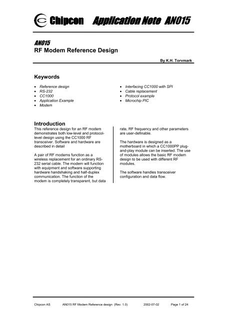
ChipconApplication Note<strong>AN015</strong><strong>AN015</strong><strong>RF</strong> <strong>Modem</strong> <strong>Reference</strong> <strong>Design</strong>By K.H. TorvmarkKeywords• <strong>Reference</strong> design• RS-232• CC1000• Application Example• <strong>Modem</strong>• Interfacing CC1000 with SPI• Cable replacement• Protocol example• Microchip PICIntroductionThis reference design for an <strong>RF</strong> modemdemonstrates both low-level and protocolleveldesign using the CC1000 <strong>RF</strong>transceiver. Software and hardware aredescribed in detailA pair of <strong>RF</strong> modems function as awireless replacement for an ordinary RS-232 serial cable. The modem will functionwith equipment and software supportinghardware handshaking and half-duplexcommunication. The function of themodem is completely transparent, but datarate, <strong>RF</strong> frequency and other parametersare user-definable.The hardware is designed as amotherboard in which a CC1000PP plugand-playmodule can be inserted. The useof modules allows the basic <strong>RF</strong> modemdesign to be used with different <strong>RF</strong>modules.The software handles transceiverconfiguration and data flow.Chipcon AS <strong>AN015</strong> <strong>RF</strong> <strong>Modem</strong> <strong>Reference</strong> design (Rev. 1.0) 2002-07-02 Page 1 of 24
ChipconApplication Note<strong>AN015</strong>Table of ContentsDescription ................................................................................................... 3Configuration............................................................................................. 4Basic operation ......................................................................................... 6Hardware....................................................................................................... 6Microcontroller .......................................................................................... 7Temperature sensor.................................................................................. 8Schematics ................................................................................................ 9Bill of materials ....................................................................................... 12Software...................................................................................................... 14Resource usage ...................................................................................... 14Packet protocol ....................................................................................... 14Source files.............................................................................................. 15Software implementation ....................................................................... 15Main program ....................................................................................... 17Interrupt handler .................................................................................. 18Operation ................................................................................................. 19Performance ............................................................................................ 22Modifications ........................................................................................... 23Source code and PCB documentation ..................................................... 23<strong>Reference</strong>s.................................................................................................. 24Chipcon AS <strong>AN015</strong> <strong>RF</strong> <strong>Modem</strong> <strong>Reference</strong> design (Rev. 1.0) 2002-07-02 Page 2 of 24
ChipconApplication Note<strong>AN015</strong>In most cases, an RS-232 serial port is full duplex. As the <strong>RF</strong> link is a half-duplex link (datacannot travel in both directions at the same time), some form of data flow control is necessary.The <strong>RF</strong> modem is designed to use hardware handshaking to tell the PC when it is able toreceive data and when it is not.ConfigurationThe <strong>RF</strong> modem can be configured by holding down button 2 (S3) when power to the modemis switched on or when the modem is restarted by pressing the reset button (S1). If themodem is connected to a PC running a suitable terminal-emulation program such as theHyperTerminal program furnished with most versions of Microsoft Windows, the user sees theConfiguration menu similar to the one shown below. The menu gives the user acces to a setof configuration and test features and enables the user to change the data rate and various<strong>RF</strong> parameters. The data can then be saved into non-volatile EEPROM data memory, so thatthe settings are retained when power is switched off. Communication between the PC and the<strong>RF</strong> modem occurs at 57600 baud, 8 data-bits, 1 stop-bit, and no parity.Figure 3: Configuration menuTable 1 provides a summary of each function in the Configuration menu.Chipcon AS <strong>AN015</strong> <strong>RF</strong> <strong>Modem</strong> <strong>Reference</strong> design (Rev. 1.0) 2002-07-02 Page 4 of 24
ChipconApplication Note<strong>AN015</strong>Basic operationAfter it has been properly set up, the <strong>RF</strong> modem can be used to replace an RS-232 cable witha wireless link. Hardware handshaking must be used. For a simple test of the system, use aterminal emulation program. Any characters typed on one computer will appear on the monitorof the other computer.The range of the system depends on the <strong>RF</strong> frequency, data rate, output power and type ofantenna used. Environmental conditions will also affect the range; interference from nearbyradio sources may reduce range drastically. If the system is used indoors, a phenomenonknown as multi-path fading may be a problem, but can usually be resolved by moving the <strong>RF</strong>modem around a bit or changing the <strong>RF</strong> frequency.In normal operation, data packets are sent when the buttons on the modem are pressed. Thecharacter sent, however, depends on the settings made in the Configuration menu. Thisfunctionality exists to be able to use the <strong>RF</strong> modem as a remote controller for a PC.Three LEDs on the <strong>RF</strong> modem are used as status indicators. The green LED (D2) functionsas a power-on indicator, the yellow LED (D4) is lit when the modem is transmitting <strong>RF</strong> data orwhen button 2 (S3) is pressed, and the red LED (D3) is lit when the modem is receiving <strong>RF</strong>data or when button 1 (S2) is pressed.HardwareFigure 4 shows a block diagram of the <strong>RF</strong> modem. The RS-232 signals are level-converted tointerface to the standard 3V CMOS signal levels used by the <strong>RF</strong> modem. The RS-232 datalines are connected to the built-in UART of the Microchip microcontroller. The <strong>RF</strong> modemfunctions as data communication equipment (DCE) according to the RS-232 definitions, sothe <strong>RF</strong> <strong>Modem</strong> can be connected to a PC using a standard serial cable.DSUBRS-232 levelconverterMicrochip PIC16LF876microcontrollerCC1000PP Plug-andplay<strong>RF</strong> moduleLEDsButtonsTemperaturesensorFigure 4: <strong>RF</strong> <strong>Modem</strong> hardware block diagramThe <strong>RF</strong> <strong>Modem</strong> has two primary buttons, three LEDs and a reset button for resetting themicrocontroller. A temperature sensor is included for crystal temperature drift compensation; afeature not implemented in the software.Chipcon AS <strong>AN015</strong> <strong>RF</strong> <strong>Modem</strong> <strong>Reference</strong> design (Rev. 1.0) 2002-07-02 Page 6 of 24
ChipconApplication Note<strong>AN015</strong>This hardware platform is very versatile; and by simply reprogramming the microcontroller,can be used for many purposes other than a modem.MicrocontrollerThe PIC16LF876 microcontroller from Microchip performs all the control functions in the <strong>RF</strong><strong>Modem</strong>. The microcontroller runs on a 10 MHz crystal clock. It interfaces to the RS-232 portusing its internal UART, which can be configured to use all standard RS-232 communicationbaud rates. Communication with the CC1000 is handled via the PIC’s built-in SPI interface, orby using general I/O-pins.The PIC16LF876 has 8 kilobytes of program memory, sufficient for these types ofapplications. It has a data memory of 368 bytes and 256 bytes of non-volatile EEPROM datamemory.PORTCPC7 I DATA_IN (RS-232: TD)RC6 O DATA_OUT (RS-232: RD)RC5 O PDATA (Output)RC4 I PDATA (Input)RC3 O CLOCK / PCLKRC2 O STROBE / PALERC1 I/O DIORC0 O READY (RS-232: CTS)PORTBPB7 I ICD pinRB6 I ICD pinRB5 I RX_TX (RS-232: RTS)RB4 I PD (RS-232: DTR)RB3 I LVP programming pinRB2 I CHP_OUT (CC1000)RB1 O AWAKE (RS-232: DSR)RB0 I DCLKPORTARA5 I/O TD LED / Button 2RA4 O Carrier Detect LED / SYNC (RS-232: CD)RA3 I Unused analog inputRA2 I/O RD LED / Button 1RA1 I RSSI inputRA0 I Temperature sensor analoginputTable 3: I/O pin usage for the PIC16LF876 microcontrollerThe microcontroller can be reprogrammed by using the In-Circuit Debugger (ICD) moduleavailable from Microchip. This module plugs into the modular jack on the <strong>RF</strong> modem. Forfurther details, consult the documentation from Microchip [2].Chipcon AS <strong>AN015</strong> <strong>RF</strong> <strong>Modem</strong> <strong>Reference</strong> design (Rev. 1.0) 2002-07-02 Page 7 of 24
ChipconApplication Note<strong>AN015</strong>The following settings should be used in Microchip’s MPLAB software when reprogrammingthe PIC:Oscillator: HSWatchdog: OFFPower-up timer: ONBrown-out detect: OFFLow-voltage program: OFFCode Protect Data EE: OFFFlash Memory Write: No Memory written to by EECONCode protect Code protection OFFErase all before program must be turned OFFTemperature sensorAn analogue temperature sensor is located on the <strong>RF</strong> modem PCB right under the plug-andplaymodule. This temperature sensor is connected to an ADC input on the microcontroller,and can be used for compensating transceiver crystal drift due to temperature. Although theideal placement for such a sensor would be right next to the transceiver crystal, this is notpossible in this reference design, because the crystal is located on another PCB. Chipconrecommends that the sensor and the crystal be positioned as close to each other as possiblein temperature compensation applications. See [4] for more information about the temperaturesensor.The current version of the <strong>RF</strong> <strong>Modem</strong> software does not implement temperature driftcompensation.Chipcon AS <strong>AN015</strong> <strong>RF</strong> <strong>Modem</strong> <strong>Reference</strong> design (Rev. 1.0) 2002-07-02 Page 8 of 24
ChipconApplication Note<strong>AN015</strong>SchematicsChipcon AS <strong>AN015</strong> <strong>RF</strong> <strong>Modem</strong> <strong>Reference</strong> design (Rev. 1.0) 2002-07-02 Page 9 of 24
ChipconApplication Note<strong>AN015</strong>Chipcon AS <strong>AN015</strong> <strong>RF</strong> <strong>Modem</strong> <strong>Reference</strong> design (Rev. 1.0) 2002-07-02 Page 10 of 24
ChipconApplication Note<strong>AN015</strong>Chipcon AS <strong>AN015</strong> <strong>RF</strong> <strong>Modem</strong> <strong>Reference</strong> design (Rev. 1.0) 2002-07-02 Page 11 of 24
ChipconApplication Note<strong>AN015</strong>Bill of materialsRef. Description Value PartC1 Capacitor 0603 100nF C_100N_0603_X7R_K_50C2 Capacitor, tantalium 3.3uF C_3U3_TAN_BC3 Capacitor, tantalium 3.3uF C_3U3_TAN_BC4 Capacitor 0603 100nF C_100N_0603_X7R_K_50C5 Capacitor 0603 100nF C_100N_0603_X7R_K_50C6 Capacitor 0603 100nF C_100N_0603_X7R_K_50C7 Capacitor 0603 100nF C_100N_0603_X7R_K_50C8 Capacitor 0603 100nF C_100N_0603_X7R_K_50C9 Capacitor 0603 100nF C_100N_0603_X7R_K_50C10 Capacitor 0603 100nF C_100N_0603_X7R_K_50C11 Capacitor 0603 100nF C_100N_0603_X7R_K_50C12 Capacitor 0603 100nF C_100N_0603_X7R_K_50C13 Capacitor 0603 100nF C_100N_0603_X7R_K_50C14 Capacitor 0603 100nF C_100N_0603_X7R_K_50C15 Capacitor 0603 15pF C_15P_0603_NP0_G_50C16 Capacitor 0603 15pF C_15P_0603_NP0_G_50D1 Diode, Si BAT254D2 LED, green, SMD LED_CL150GCDD3 LED, red, SMD LED_CL150URCDD4 LED, yellow, SMD LED_CL150YCDD5 Diode, Si BAT254D6 Diode, Si BAT254H1 Circuit Board Support Distance 12.5mmH2 Circuit Board Support Distance 12.5mmH3 Circuit Board Support Distance 12.5mmH4 Circuit Board Support Distance 12.5mmP1 D-Sub, 9 pin, female DSUB_9FP2 2 pin terminal, screw SCREW_TERM_2P3 Connector, 0.9 mm pin, female CON6_FEMALEP4 Connector, 0.9 mm pin, female CON6_FEMALEP5 Connector, 0.9 mm pin, female CON6_FEMALEP6 SMA connector, straight SMAP7 Connector, 0.9 mm pin, female CON6_FEMALEP8 6-pin modular jack MODULAR_CONN_6P9 DC jack, 2.5mm center pin DC_JACK_2.5R1 Resistor 0603 47kΩ R_47K_0603_GR2 Resistor 0603 470Ω R_470_0603_JR3 Resistor 0603 470Ω R_470_0603_JR4 Resistor 0603 470Ω R_470_0603_JR5 Resistor 0603 0Ω R_0_0603R8 Resistor 0603 0Ω R_0_0603S1 Push button, SMD PUSH_BUTTONS2 Push button, SMD PUSH_BUTTONS3 Push button, SMD PUSH_BUTTONTP1 Testpoint TESTPINTP2 Testpoint TESTPINTP3 Testpoint TESTPINTP4 Testpoint TESTPINTP5 Testpoint TESTPINTP6 Testpoint TESTPINTP7 Testpoint TESTPINChipcon AS <strong>AN015</strong> <strong>RF</strong> <strong>Modem</strong> <strong>Reference</strong> design (Rev. 1.0) 2002-07-02 Page 12 of 24
ChipconApplication Note<strong>AN015</strong>TP8 Testpoint TESTPINU1 National Semiconductor LP2981 3.0VLP2981-3.0Vlow drop-out regulatorU2 Maxim RS-232 Transceiver, SO-16 MAX3232U3 Maxim RS-232 Transceiver, SO-16 MAX3232U4 Microchip PIC16LF876 microcontroller,PIC16LF876SO-28U5 National Semiconductor LM61LM61temperature sensor, SOT23X1 10.000 MHz Crystal, 16pF load, HC-49-SMDX_10.000/50/30/10/16Chipcon AS <strong>AN015</strong> <strong>RF</strong> <strong>Modem</strong> <strong>Reference</strong> design (Rev. 1.0) 2002-07-02 Page 13 of 24
ChipconApplication Note<strong>AN015</strong>SoftwareThe software for the PIC microcontroller is written for the IAR PIC16 C-compiler.The highest priority task of the software is performed by the external interrupt handler, whichis triggered by transitions in the DCLK clock coming from the CC1000.The main program handles state transitions, writes data in the RX buffer to the UART, readsany incoming data from the UART and stores it in the TX buffer, and handles the time-out andbutton debouncing timers.Configuration of the CC1000 is performed either using general I/O pins or the PIC’s SPIinterface. If the symbol ‘SPI’ is defined, the SPI code is used; otherwise the slower general I/Opin-based code is used. For more details on CC1000 configuration issues, see Chipconapplication note AN009.Resource usageMost of the microcontroller’s SRAM data memory is used for buffering the incoming andoutgoing data streams. When data arrives from the UART, the UART main program storesthe data in the TX buffer, and an <strong>RF</strong> packet is sent only after a timeout or when the buffer isfull.When data is received via <strong>RF</strong>, the data is buffered in the RX ring buffer, and sent to the PCvia the UART.The EEPROM data memory is used for non-volatile storage of configuration parameters.These parameters may be changed by entering the configuration mode at start up. Therequired data is read from the EEPROM memory as needed.Packet protocolThe protocol chosen for the <strong>RF</strong> modem is a simple variable-length packet protocol.Field Length Format, usagePreamble 32 bits Alternating 0s and 1sStart-of-Frame / 2 bytes 0x33CC for modem applicationUnique IdentifierUnit address 1 byte 0 for broadcast, 1-255 for unit address, not currently usedData length 1 byte Length of data payloadData Variable Data payload, maximum length is 64 bytesTable 4: Data protocolThe maximum packet length for the <strong>RF</strong> modem software is 64 bytes. If the modem receives apacket a greater data length than this, the packet is discarded.Chipcon AS <strong>AN015</strong> <strong>RF</strong> <strong>Modem</strong> <strong>Reference</strong> design (Rev. 1.0) 2002-07-02 Page 14 of 24
ChipconApplication Note<strong>AN015</strong>Source filesThe software consists of several source code files. A quick overview of the files is provided inthe table below.File namerfmodem_cc1000.cmodemhw.hcc1000.ccc1000.hconfigure.cconfigure.hgetchar.cputchar.csimpleio.csimpleio.hinterrupt.cmain.hShort descriptionMain program source fileHeader file defining the I/O pin usageFunction library for configuring and using CC1000. See applicationnote AN009 for more information.Header file for cc1000.c, also includes definitions for all the registersof the CC1000.Configuration menu source fileHeader file for configure.cImplements the C library function getchar() using the UARTImplements the C library function putchar() using the UARTImplements simple replacements for standard I/O functions likeprintf() and scanf(). Uses the getchar() and putchar() functionsimplemented in getchar.c and putchar.cHeader file for simpleio.cContains the <strong>RF</strong> modem interrupt handlerHeader file used by interrupt.c to gain access to variables sharedwith the main programTable 5: Summary of software source filesAll of these files can be downloaded from Chipcon’s web site at www.chipcon.com.All other files referenced are standard ANSI C library files and should be provided by thecompiler vendor.Software implementationThe software is implemented as a state machine with three different states.RESETIDLETX Buffer full or timeout elapsedValid preamble and SOF detectedRXTXFinished receiving data or error detectedFinshed sending data in bufferFigure 5: State diagramIn the IDLE state, the modem looks for a valid incoming preamble and for data from the RS-232 interface. If the <strong>RF</strong> modem detects a valid incoming preamble and it is followed by a validstart-of-frame (SOF) word, the modem enters the RX state. If the transmit buffer is full or if theChipcon AS <strong>AN015</strong> <strong>RF</strong> <strong>Modem</strong> <strong>Reference</strong> design (Rev. 1.0) 2002-07-02 Page 15 of 24
ChipconApplication Note<strong>AN015</strong>timeout period has expired since the last character was received from the RS-232 interface,the modem enters the TX state.In the RX state, header data is handled in the interrupt handler, data is buffered in a circularbuffer and transmitted via the RS-232 interface in the main program.In the TX state, the data in the transmit buffer is sent to the CC1000 for transmission.State switching is performed by the main program; the interrupt routine updates a NextStatevariable when a state change is to occur.Chipcon AS <strong>AN015</strong> <strong>RF</strong> <strong>Modem</strong> <strong>Reference</strong> design (Rev. 1.0) 2002-07-02 Page 16 of 24
ChipconApplication Note<strong>AN015</strong>Main programThe figure below is a flowchart of the main program, implemented in the main() function inrfmodem_cc1000.c.Power upInitialise PICregistersInitialise andcalibrate CC1000Button 2pressed?YesEnterconfigurationmodeNoShow startupmessageLoop foreverShould statechange occur?YesChange stateNoUpdate state ofaveraging filterData in RXcircular buffer?YesSend data toUARTNoUART receiveddata?YesStore data in TXbufferBuffer full?YesEnter TX stateNoNoTime-out timertriggered?YesNoButtondebouncingtimertriggered?YesButtonpressed?YesPut character inbufferEnter TX stateNoNoFigure 6: Main program flowchartChipcon AS <strong>AN015</strong> <strong>RF</strong> <strong>Modem</strong> <strong>Reference</strong> design (Rev. 1.0) 2002-07-02 Page 17 of 24
ChipconApplication Note<strong>AN015</strong>Interrupt handlerThe figure below is a flow chart of the interrupt handler, implemented in interrupt.c forinterrupts generated by transitions on the DCLK pin of the CC1000. The processing that isdone depends on the current state of the software.Interrupt triggeredTXState?IDLERXWrite bit toCC1000Read bit fromCC1000Read bit fromCC1000Sent entirepacket?YesFinished withbyte?Declared validpreamble?NoYesYesFinished withbyte?Enter IDLE stateSOF part 2?YesSOF correct?YesReceivedSOF?NoEnter RX modeNoYesNoNoEnter IDLE stateReceiving validpreamble bits?NoLoad next byteinto shift registerNoNoPacket size?YesStore valueDeclare errorNoYesWrite byte to RXcircular bufferYesEnough validpreamble bitsreceived?YesFinished withpacket?YesEnter IDLE stateDeclare preamblefoundNoNoReturn frominterruptFigure 7: Interrupt handler flow chartChipcon AS <strong>AN015</strong> <strong>RF</strong> <strong>Modem</strong> <strong>Reference</strong> design (Rev. 1.0) 2002-07-02 Page 18 of 24
ChipconApplication Note<strong>AN015</strong>The figure below shows the CC1000 being configured by using the SPI interface of themicrocontroller. The configuration is very fast; programming a register takes 9 us. The SPIinterface is configured for reading data on the falling edge of the clock and the clock idle stateis set to HIGH to communicate with the CC1000. As the transmit and receive lines of the SPIinterface are connected together to form a two-wire interface, the SPI output is set to be aninput when reading data from the CC1000.Figure 9: I/O lines during CC1000 configurationChipcon AS <strong>AN015</strong> <strong>RF</strong> <strong>Modem</strong> <strong>Reference</strong> design (Rev. 1.0) 2002-07-02 Page 20 of 24
ChipconApplication Note<strong>AN015</strong>Figure 10 shows a long string of ASCII characters being received(‘1234567890abcdefghijklmnopqrstuvwxyzABCDEFGHIJKLMNOPQRSTUVWXYZ’). Thisstring is 62 characters long, and therefore split into two packets. In between the two packets isalso a rejected packet, the <strong>RF</strong> <strong>Modem</strong> goes into the RX state, but the second half of the SOFis not correct, and the modem returns to the IDLE state.Figure 10: I/O lines during reception of long packetsChipcon AS <strong>AN015</strong> <strong>RF</strong> <strong>Modem</strong> <strong>Reference</strong> design (Rev. 1.0) 2002-07-02 Page 21 of 24
ChipconApplication Note<strong>AN015</strong>The figure below is an enlargement of the middle of the transmission shown in Figure 10. Thetime between UART transmissions is 670us.Figure 11: Close-up of middle of long packetPerformanceThe C-code presented in this application note works for data rates up to 19.2kbit/s. At ratesfaster than this, the interrupt routine does not execute fast enough to keep up with the dataflow. For a data rate of 38.4kbit/s, the PIC16 microcontroller has only time to execute 65instructions for each bit. The machine code created by the compiler is not fast enough to dothis, but a handwritten interrupt routine in assembly can be able to execute fast enough. Dueto time by the microcontroller during mode switching, packet loss is higher at 19.2kbit/s than atthe lower data rates. Implementing an optimized interrupt handler in assembly is left as anexercise for the reader.Operation at 76.8kbit/s is not possible with the current design, as this leaves only 32instructions for each bit – too few to implement the functionality needed. While the CC1000has no problems operating at a data rate of 76.8 kbit/s, the microcontroller does. There aretwo ways to reach this data rate; either use a faster microcontroller or a byte-oriented serialinterface to handle the data interface.The PIC16F876 has a maximum clock rate of 10 MHz when run on a 3.0V supply voltage. Itprocesses instructions at one-fourth this rate, executing 2.5 million instructions per second(MIPS). Preliminary information from Microchip indicates that the PIC18F242 may be a viablealternative. The PIC18 is pin-compatible, and can run at 20 MHz (5 MIPS) at 3.0V. Theinstruction set is also more efficient, so the PIC18 should be able to handle a 76.8kbit/s dataChipcon AS <strong>AN015</strong> <strong>RF</strong> <strong>Modem</strong> <strong>Reference</strong> design (Rev. 1.0) 2002-07-02 Page 22 of 24
ChipconApplication Note<strong>AN015</strong>rate. Because the instruction set is different, the source code would have to be ported to IAR’sPIC18 compiler.Several other available microcontrollers run at speeds of up to 1MIPS/MHz clock. For instancethe new megaAVR microcontrollers from Atmel can run at up to 8 MHz with a 3.0V supplyvoltage, giving a performance of 8 MIPS. This makes operation with very high data ratespossible.Another way of increasing the maximum data rate is to use a byte-oriented serial port tointerface with the CC1000. A USART or an SPI interface can be used. This has not been donein this reference design because the USART is used for RS-232 interface and the SPIinterface is used for CC1000 configuration. In a design that does not need an RS-232interface, the USART can be connected to the data interface of the CC1000 instead. This willdecrease the microcontroller’s processing-load by a factor of almost 8. Byte synchronizationwill have to be handled by looking for the end of the SOF, and then starting USART receptionat the correct time.ModificationsThe <strong>RF</strong> modem software can be modified for different applications:• For low-power use, the <strong>RF</strong> modem software can be modified so that the receiver pollsregularly instead of being on all the time. If this is implemented, the preamble shouldbe lengthened so that it lasts longer than the polling period.• Support for repeaters can be quite easily added by implementing a hop counter.• For adding error correction and/or detection, an ACK/NAK handshake protocol can beadded, together with CRC checking. Some form of forward error correction (FEC) canbe beneficial.• Temperature compensation of the reference crystal may be added for applicationswhere very good frequency accuracy is important.Source code and PCB documentationThe PCB docuemtnation files (including Gerber-format files for PCB production) and fullsource code for the <strong>RF</strong> modem software can be downloaded from Chipcon’s web site atwww.chipcon.comChipcon AS <strong>AN015</strong> <strong>RF</strong> <strong>Modem</strong> <strong>Reference</strong> design (Rev. 1.0) 2002-07-02 Page 23 of 24
ChipconApplication Note<strong>AN015</strong><strong>Reference</strong>s[1] CC1000PP Plug-and-play reference design, Chipcon 2002[2] MPLAB ICD User’s Guide, Microchip Technology Inc. 2000[3] Microchip PIC16F87X Data Sheet, Microchip Technology Inc. 1999[4] LM61 2.7V, SOT-23 or TO-92 Temperature Sensor Data Sheet, NationalSemiconductor Corporation 2001Contact InformationChipcon is a world-wide supplier of <strong>RF</strong>ICs. For further information on the products fromChipcon please contact us or visit our web site. An updated list of distributors is also availableat our web site.Chipcon ASGaustadalléen 21N-0349 Oslo,NORWAYTelephone : (+47) 22 95 85 44Telefax : (+47) 22 95 85 46E-mail : wireless@chipcon.comWeb site : http://www.chipcon.comDisclaimerChipcon AS believes the furnished information is correct and accurate at the time of this printing. However, ChipconAS reserves the right to make changes to this application note and the product(s) it describes without notice.Chipcon AS assumes no responsibility for the use of the described information. Information and product updates aswell as the most recent news are available at Chipcon’s web site.Smart<strong>RF</strong> ® is a registered trademark of Chipcon AS. All other trademarks or registered trademarks are the soleproperty of their respective owners.Chipcon AS <strong>AN015</strong> <strong>RF</strong> <strong>Modem</strong> <strong>Reference</strong> design (Rev. 1.0) 2002-07-02 Page 24 of 24