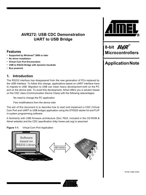
USB CDC Demonstration UART to USB Bridge
USB CDC Demonstration UART to USB Bridge
USB CDC Demonstration UART to USB Bridge

Create successful ePaper yourself
Turn your PDF publications into a flip-book with our unique Google optimized e-Paper software.
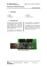
2. Hardware Requirements3. Software Requirements4. STK525 Default SettingsThe <strong>USB</strong> <strong>CDC</strong> application requires the following hardware:1. AT90<strong>USB</strong> Evaluation Board (STK525)2. AT90<strong>USB</strong> microcontroller with default fac<strong>to</strong>ry configuration (including <strong>USB</strong> bootloader)3. <strong>USB</strong> cable (Standard A <strong>to</strong> Mini B)4. RS232 crossed Cable (DB9 male <strong>to</strong> DB9 female)5. PC running on Windows ® (2000, XP) with <strong>USB</strong> 1.1 or 2.0 hostNote: Another STK 525 and <strong>USB</strong> port are required if the PC has no RS232 interface.The software needed for this application:1. FLIP software (Device Firmware Upgrade <strong>to</strong>ol)2. usb_cdc.a90 (included in <strong>USB</strong> CD-ROM )3. Hyperterminal application or similarThe STK525 board must be configured as below:Figure 4-1.STK525 Board27619A–<strong>USB</strong>–03/06
All the jumpers should be opened, only the Vcc Source jumper VBUS5 should be set as below:Figure 4-2.Vcc JumpersVccSourceReg 5Reg3.3VBUS5STK5VThe microcontroller must be properly placed on its socket. Please refer <strong>to</strong> STK525 HardwareUser’s Guide.5. Device Firmware UpgradeThe first thing <strong>to</strong> do before starting the demo is <strong>to</strong> load the HEX file in<strong>to</strong> the on-chip Flash memoryof the microcontroller. The “Flip” software is the <strong>to</strong>ol used <strong>to</strong> upgrade the firmware (availablefreely from the <strong>USB</strong> CD-ROM or Atmel website).The following steps should be completed <strong>to</strong> allow the device starting DFU (Device FirmwareUpgrade )mode and load the HEX file:1. Install Flip software (Flip version 3.0 or above is required).2. Connect the STK525 board <strong>to</strong> the PC using the <strong>USB</strong> cable (Standard A <strong>to</strong> Mini B).3. Push the HWB (Hardware Bootloader) but<strong>to</strong>n4. Push the RST (Reset) but<strong>to</strong>n5. Release the RST but<strong>to</strong>n6. Release the HWB but<strong>to</strong>n7. If your hardware conditions explained above are correct, a new device detection wizardwill be displayed. Please follow the instructions (the INF file is located in the <strong>USB</strong> subdirec<strong>to</strong>ryfrom Flip installation: “install path:\ATMEL\FLIP\FLIPx.x.x\usb”).7619A–<strong>USB</strong>–03/063
Figure 5-1.New Device Detection WizardFigure 5-2.Driver’s Location8. Check the Device Manager, and you should see the same icon (Jungo ® icon) as shownin the figure below. If not start again from the step 2.47619A–<strong>USB</strong>–03/06
Figure 5-3.Device Manager7619A–<strong>USB</strong>–03/065
Once your device is connected in DFU mode with Jungo driver loaded, launch the FLIP softwareand follow the instructions explained below:1. Select AT90<strong>USB</strong> deviceFigure 5-4.Device Selection67619A–<strong>USB</strong>–03/06
2. Select the <strong>USB</strong> as communication modeFigure 5-5.<strong>USB</strong> Communication Mode7619A–<strong>USB</strong>–03/067
3. Open the communicationFigure 5-6.Open the <strong>USB</strong> Communication87619A–<strong>USB</strong>–03/06
4. Choose the HEX file <strong>to</strong> load (the HEX file is included in the <strong>USB</strong> CD-ROM:usb_cdc.a90)Figure 5-7.HEX File <strong>to</strong> Load7619A–<strong>USB</strong>–03/069
5. Load the HEX file (Check Erase, Program and Verify, then Push Run but<strong>to</strong>n)Figure 5-8.HEX File Loading107619A–<strong>USB</strong>–03/06
6. Start the application.Figure 5-9.Start ApplicationNote:The AT90<strong>USB</strong> bootloader will detach and jump in<strong>to</strong> the user application when “Start Application” but<strong>to</strong>n is pressed.7619A–<strong>USB</strong>–03/0611
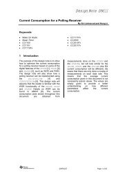
6. Quick StartOnce your device is programmed with usb_cdc.a90 file, click on Start Application but<strong>to</strong>n on Flipor push the reset but<strong>to</strong>n from the STK525 board <strong>to</strong> start the <strong>CDC</strong> demonstration. A new devicedetection wizard will appear, point the wizard <strong>to</strong> the inf folder included in the <strong>CDC</strong> package.Check that your device is enumerated as Com port (see Figure 6-1), then you can use theSTK525 as a Virtual Com Port or <strong>USB</strong> <strong>to</strong> <strong>UART</strong> bridge.Figure 6-1.<strong>CDC</strong> enumeration127619A–<strong>USB</strong>–03/06
The figure below shows the Hardware used by the demo:Figure 6-2.Hardware usedRS232 Connec<strong>to</strong>r<strong>USB</strong> Connec<strong>to</strong>rJoystick6.1 Virtual Com Port DemoThe purpose of the Virtual Com Port demonstration is <strong>to</strong> communicate with a RS232 PC applicationwithout any software modification.Follow the instructions below <strong>to</strong> start the demo:7619A–<strong>USB</strong>–03/0613
1. Lauch the HyperTerminal application and select the right Com port as indicated in thedevice manager.Figure 6-3.Com Port selection2. Press the joystick and you will see the selection or the direction status written on theHyperTerminal window.Figure 6-4.Virtual Com Port Demo6.2 <strong>USB</strong> <strong>to</strong> <strong>UART</strong> <strong>Bridge</strong>The aim of the <strong>USB</strong> <strong>to</strong> <strong>UART</strong> bridge is <strong>to</strong> transfer data in full duplex mode between <strong>UART</strong> and<strong>USB</strong> interface. This application can be used <strong>to</strong> connect any RS232 device <strong>to</strong> a PC which has notan RS232 interface.147619A–<strong>USB</strong>–03/06
Follow the instruction hereunder <strong>to</strong> start the demo:1. Connect the RS232 port of the STK 525 <strong>to</strong> The PC RS232 port.Note: If the PC has no RS232 interface you can use another STK525: Connect the two boards with aRS232 crossed cable and connect Each board <strong>to</strong> an <strong>USB</strong> port of the PC.2. Lauch two HyperTerminal applications (one with the RS232 port and the second withthe Virtual Com port) with the same configuration (Baudrate, Data bits, Parity, .S<strong>to</strong>pbits, Flow control).3. Write something in one HyperTerminal, it will be displayed in the other.Figure 6-5.<strong>USB</strong> <strong>to</strong> <strong>UART</strong> <strong>Bridge</strong>7619A–<strong>USB</strong>–03/0615
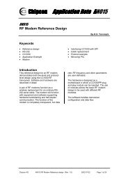
7. Application OverviewThe <strong>CDC</strong> application allows the user <strong>to</strong> simulate a RS232 port using the <strong>USB</strong> hardware. Thedevice shows as a Com port instead of <strong>USB</strong> device which allows the user <strong>to</strong> use whithoutchanging his PC application.From the embedded side, the <strong>UART</strong> driver is replaced by the <strong>UART</strong>-<strong>USB</strong> Driver. The user has<strong>to</strong> use the <strong>UART</strong>-<strong>USB</strong> functions instead of the <strong>UART</strong> functions <strong>to</strong> communicate with the PC.Once the device has enumerated, the application ensures a full duplex data transfer betweenthe PC and the peripheral.The figure below shows the structure:Figure 7-1.<strong>USB</strong> <strong>to</strong> <strong>UART</strong> migrationPC ApplicationPC Application<strong>UART</strong> API<strong>UART</strong> hardware<strong>UART</strong> API<strong>CDC</strong> Drivers<strong>USB</strong> hardwareRS232<strong>USB</strong><strong>UART</strong> hardware<strong>USB</strong> hardware<strong>UART</strong> Driver<strong>UART</strong>- <strong>USB</strong>DriverEmbeddedApplicationEmbeddedApplication167619A–<strong>USB</strong>–03/06
8. FirmwareAs explained in the <strong>USB</strong> Firmware Architecture document (Doc 7603, included in the <strong>USB</strong> CD-ROM ) all <strong>USB</strong> firmware packages are based on the same architecture (please refer <strong>to</strong> this documentfor more details).Figure 8-1.<strong>USB</strong> <strong>CDC</strong> Firmware ArchitectureStart upEnumerationmanagementmain.cscheduler.cconfig.hconf_scheduler.h<strong>CDC</strong> applicationmanagementHID applicationusb_task.husb_task.ccdc_task.ccdc_task.hAPIusb_standard_request.cusb_standard_request.husb_specific_request.cusb_specific_request.husb_descrip<strong>to</strong>rs.cusb_descrip<strong>to</strong>rs.hconf_usb.huart_usb_lib.cuart_usb_lib.hDriversusb_drv.cusb_drv.hstk_525.cstk_525.hHardware<strong>USB</strong> hardware interfaceShould not be modified by user Can be modified by user Added by userThis section is dedicated <strong>to</strong> the <strong>CDC</strong> module only. The cus<strong>to</strong>mization of the files described hereafterallow the user <strong>to</strong> build his own <strong>CDC</strong> Application.7619A–<strong>USB</strong>–03/0617
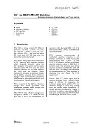
8.1 cdc_task.cThis file contains the functions <strong>to</strong> initialize the hardware which will be used by the application,collect data and transfer it.Figure 8-2.<strong>CDC</strong> ApplicationVirtual ComPortJoystic pressed??Send data trough <strong>USB</strong>InitializationData received onData receivedon <strong>USB</strong>??<strong>UART</strong>=Fifo endpoint size??Send data trough <strong>UART</strong>Send data trough <strong>USB</strong><strong>USB</strong><strong>UART</strong> <strong>UART</strong><strong>USB</strong>Data received on<strong>UART</strong> !=0&&!timeout??<strong>USB</strong>-<strong>UART</strong><strong>Bridge</strong>187619A–<strong>USB</strong>–03/06
8.1.1 cdc_task_init8.1.2 cdc_taskThis function performs the initialization of the <strong>CDC</strong> parameters and hardware resources(joystick...).This function manages the data transfer for the two demonstrations (Virtual Com Port and <strong>UART</strong><strong>to</strong> <strong>USB</strong> <strong>Bridge</strong>).8.2 uart_usb_lib8.2.1 uart_usb_test_hitThis function checks if at least one character has been received on the <strong>USB</strong>.8.2.2 uart_usb_getcharThis function returns the byte received in the OUT endpoint FIFO.8.2.3 uart_usb_putcharThis function writes the byte put in parameter in<strong>to</strong> the <strong>USB</strong> IN endpoint FIFO. It also replaces theputchar function of the <strong>UART</strong> library. For example the printf will be based on uart_usb_putcharfuction instead of putchar.8.2.4 uart_usb_tx_readyThis function checks if a byte can be written in the IN endpoint FIFO.8.2.5 uart_usb_flushThis function sends data s<strong>to</strong>red in the IN endpoint.8.3 stk_525.c.9. PC Software10. LimitationsThis file contains all the routines <strong>to</strong> manage the STK 525 board resources (joystick, potentiometer,temperature sensor, LEDs...).The <strong>CDC</strong> application uses the native Windows drivers. It requires only an INF file located in theinf folder from the <strong>CDC</strong> package.This application does not work with Windows 98 and ME (no native driver of <strong>CDC</strong> device).This application can work with Linux OS, but support depends on configuration.11. Related Documentation• AVR <strong>USB</strong> Datasheet• <strong>USB</strong> Firmware Architecture• <strong>USB</strong> <strong>CDC</strong> class specification7619A–<strong>USB</strong>–03/0619
Atmel Corporation2325 Orchard ParkwaySan Jose, CA 95131, USATel: 1(408) 441-0311Fax: 1(408) 487-2600Regional HeadquartersEuropeAtmel SarlRoute des Arsenaux 41Case Postale 80CH-1705 FribourgSwitzerlandTel: (41) 26-426-5555Fax: (41) 26-426-5500AsiaRoom 1219Chinachem Golden Plaza77 Mody Road TsimshatsuiEast KowloonHong KongTel: (852) 2721-9778Fax: (852) 2722-1369Japan9F, Tonetsu Shinkawa Bldg.1-24-8 ShinkawaChuo-ku, Tokyo 104-0033JapanTel: (81) 3-3523-3551Fax: (81) 3-3523-7581Atmel OperationsMemory2325 Orchard ParkwaySan Jose, CA 95131, USATel: 1(408) 441-0311Fax: 1(408) 436-4314Microcontrollers2325 Orchard ParkwaySan Jose, CA 95131, USATel: 1(408) 441-0311Fax: 1(408) 436-4314La ChantrerieBP 7060244306 Nantes Cedex 3, FranceTel: (33) 2-40-18-18-18Fax: (33) 2-40-18-19-60ASIC/ASSP/Smart CardsZone Industrielle13106 Rousset Cedex, FranceTel: (33) 4-42-53-60-00Fax: (33) 4-42-53-60-011150 East Cheyenne Mtn. Blvd.Colorado Springs, CO 80906, USATel: 1(719) 576-3300Fax: 1(719) 540-1759Scottish Enterprise Technology ParkMaxwell BuildingEast Kilbride G75 0QR, ScotlandTel: (44) 1355-803-000Fax: (44) 1355-242-743RF/Au<strong>to</strong>motiveTheresienstrasse 2Postfach 353574025 Heilbronn, GermanyTel: (49) 71-31-67-0Fax: (49) 71-31-67-23401150 East Cheyenne Mtn. Blvd.Colorado Springs, CO 80906, USATel: 1(719) 576-3300Fax: 1(719) 540-1759Biometrics/Imaging/Hi-Rel MPU/High Speed Converters/RF DatacomAvenue de RochepleineBP 12338521 Saint-Egreve Cedex, FranceTel: (33) 4-76-58-30-00Fax: (33) 4-76-58-34-80Literature Requestswww.atmel.com/literatureDisclaimer: The information in this document is provided in connection with Atmel products. No license, express or implied, by es<strong>to</strong>ppel or otherwise, <strong>to</strong> anyintellectual property right is granted by this document or in connection with the sale of Atmel products. EXCEPT AS SET FORTH IN ATMEL’S TERMS AND CONDI-TIONS OF SALE LOCATED ON ATMEL’S WEB SITE, ATMEL ASSUMES NO LIABILITY WHATSOEVER AND DISCLAIMS ANY EXPRESS, IMPLIED OR STATUTORYWARRANTY RELATING TO ITS PRODUCTS INCLUDING, BUT NOT LIMITED TO, THE IMPLIED WARRANTY OF MERCHANTABILITY, FITNESS FOR A PARTICULARPURPOSE, OR NON-INFRINGEMENT. IN NO EVENT SHALL ATMEL BE LIABLE FOR ANY DIRECT, INDIRECT, CONSEQUENTIAL, PUNITIVE, SPECIAL OR INCIDEN-TAL DAMAGES (INCLUDING, WITHOUT LIMITATION, DAMAGES FOR LOSS OF PROFITS, BUSINESS INTERRUPTION, OR LOSS OF INFORMATION) ARISING OUTOF THE USE OR INABILITY TO USE THIS DOCUMENT, EVEN IF ATMEL HAS BEEN ADVISED OF THE POSSIBILITY OF SUCH DAMAGES. Atmel makes norepresentations or warranties with respect <strong>to</strong> the accuracy or completeness of the contents of this document and reserves the right <strong>to</strong> make changes <strong>to</strong> specificationsand product descriptions at any time without notice. Atmel does not make any commitment <strong>to</strong> update the information contained herein. Unless specifically providedotherwise,Atmel products are not suitable for, and shall not be used in, au<strong>to</strong>motive applications. Atmel’sAtmel’s products are not intended, authorized, or warranted for use ascomponents in applications intended <strong>to</strong> support or sustain life.© Atmel Corporation 2006. All rights reserved. Atmel ® , logo and combinations thereof, are registered trademarks, and Everywhere You Are ®are the trademarks of Atmel Corporation or its subsidiaries. Other terms and product names may be trademarks of others.Printed on recycled paper.7619A–<strong>USB</strong>–03/06