Atmel QTouch Library User Guide
Atmel QTouch Library User Guide
Atmel QTouch Library User Guide

You also want an ePaper? Increase the reach of your titles
YUMPU automatically turns print PDFs into web optimized ePapers that Google loves.
<strong>Atmel</strong> <strong>QTouch</strong> <strong>Library</strong><strong>User</strong> <strong>Guide</strong>Supports <strong>QTouch</strong> ® and QMatrix ® acquisition for Keys, Slidersand RotorsRev. 8207K-AT42-09/11
5.6.4.2 qt_touch_lib_config_data_t .................................................................................. 265.6.4.3 qt_touch_lib_measure_data_t .............................................................................. 275.6.4.4 qt_burst_lengths ................................................................................................... 275.6.4.5 tag_sensor_t ......................................................................................................... 285.6.4.6 qt_lib_siginfo_t ..................................................................................................... 285.6.5 Public Functions ..................................................................................................................... 295.6.5.1 qt_set_parameters ............................................................................................... 295.6.5.2 qt_enable_key ...................................................................................................... 305.6.5.3 qt_enable_rotor .................................................................................................... 305.6.5.4 qt_enable_slider ................................................................................................... 315.6.5.5 qt_init_sensing ..................................................................................................... 315.6.5.6 qt_measure_sensors ............................................................................................ 315.6.5.7 qt_calibrate_sensing ............................................................................................ 325.6.5.8 qt_reset_sensing .................................................................................................. 335.6.5.9 qt_get_sensor_delta ............................................................................................. 335.6.5.10 qt_get_library_sig ............................................................................................. 335.6.6 Sequence of Operations and Using the API ........................................................................... 335.6.6.1 Channel Numbering ............................................................................................. 345.6.6.1.1 Channel numbering when using <strong>QTouch</strong> acquisition method ......................... 345.6.6.1.2 Channel numbering when using QMatrix acquisition method ......................... 405.6.6.2 Sensor Numbering ............................................................................................... 425.6.6.3 Filtering Signal Measurements ............................................................................. 435.6.6.4 Allocating unused Port Pins for <strong>User</strong> Application ................................................. 455.6.6.5 Disabling and Enabling of Pull-up for AVR devices ............................................. 465.6.7 Constraints ............................................................................................................................. 465.6.7.1 <strong>QTouch</strong> acquisition method constraints ............................................................... 465.6.7.2 QMatrix acquisition method constraints ............................................................... 465.6.7.3 Design <strong>Guide</strong>lines for QMatrix acquisition method systems ................................ 475.6.8 Frequency of operation (Vs) Charge cycle/dwell cycle times: ................................................ 485.6.9 Interrupts ................................................................................................................................ 495.6.10 Integrating <strong>QTouch</strong> libraries in your application ..................................................................... 495.6.10.1 Directory structure of the library files ................................................................ 495.6.10.2 Integrating <strong>QTouch</strong> acquisition method libraries in your application ................ 515.6.10.2.1 Example for 8bit AVR .................................................................................... 535.6.10.2.2 Example for ATSAM ...................................................................................... 545.6.10.2.3 Checklist of items for integrating <strong>QTouch</strong> acquisition method libraries ......... 555.6.10.3 Integrating QMatrix acquisition method libraries in your application ................ 565.6.10.3.1 Example for 8bit AVR .................................................................................... 565.6.10.3.2 Example for 32bit AVR .................................................................................. 635.6.10.3.3 Checklist of items for integrating QMatrix Capacitive sensing libraries ......... 675.6.10.4 Common checklist items ................................................................................... 675.6.10.4.1 Configuring the stack size for the application ................................................ 675.6.11 Example project files .............................................................................................................. 685.6.11.1 Using the Sample projects ................................................................................ 695.6.11.2 Example applications for <strong>QTouch</strong> acquisition method libraries ........................ 695.6.11.2.1 Selecting the right configuration .................................................................... 695.6.11.2.2 Changing the settings to match your device .................................................. 705.6.11.2.3 Changing the library configuration parameters .............................................. 715.6.11.2.4 Using the example projects ........................................................................... 735.6.11.3 Example applications for QMatrix acquisition method libraries ........................ 735.6.11.3.1 Selecting the right configuration .................................................................... 745.6.11.3.2 Changing the library configuration parameters .............................................. 755.6.11.3.3 Using the example projects ........................................................................... 765.6.11.4 Adjusting the Stack size when using IAR IDE .................................................. 765.6.11.5 Optimization levels ............................................................................................ 775.6.11.6 Debug Support in Example applications........................................................... 783
5.6.11.6.1 Debug Support in the sample applications for EVK2080 and QT600 boards 785.6.11.6.2 How to turn on the debug option.................................................................... 785.6.11.6.3 Debug Interface if USB Bridge board is not available ................................... 795.7 <strong>Library</strong> Variants ............................................................................................................... 795.7.1 <strong>QTouch</strong> Acquisition method library variants ........................................................................... 795.7.1.1 Introduction ........................................................................................................... 795.7.1.2 Support for different compiler tool chains............................................................. 805.7.1.3 <strong>QTouch</strong> Acquisition method library naming conventions ..................................... 805.7.1.3.1 Naming convention for libraries to be used with GCC tool chain .................... 805.7.1.3.2 Naming convention for libraries to be used with IAR Embedded Workbench 815.7.1.4 <strong>QTouch</strong> acquisition method library variants ......................................................... 815.7.1.5 Port combinations supported for SNS and SNSK pin configurations .................. 825.7.1.5.1 Tips on pin assignments for the sensor design using one pair of SNS/SNSKports 825.7.1.5.2 Port combinations supported for two port pair SNS and SNSK pinconfigurations .................................................................................................................. 835.7.1.6 Sample applications and Memory requirements for <strong>QTouch</strong> acquisition methodlibraries 855.7.2 QMatrix acquisition method library variants............................................................................ 855.7.2.1 Introduction ........................................................................................................... 855.7.2.2 Support for different compiler tool chains............................................................. 855.7.2.3 QMatrix Acquisition method library naming conventions ..................................... 855.7.2.4 QMatrix acquisition method library variants ......................................................... 885.7.2.4.1 Devices supported for QMatrix Acquisition ..................................................... 885.8 PIN Configuration for <strong>QTouch</strong> Libraries .......................................................................... 885.8.1 Pin Configuration for <strong>QTouch</strong> Acquisition Method .................................................................. 885.8.1.1 Rules for configurable SNS-SNSK Mask Generation .......................................... 895.8.1.1.1 Example for 8 channel interport mask Calculation with one port pair ............. 905.8.1.1.2 Example for 8 channel intraport mask Calculation with two port pairs............ 915.8.1.1.3 Example for 12 channel intraport-interport mask Calculation with two portpairs 925.8.1.1.4 Example for 16 channel intreport-interport mask Calculation with two portpairs 935.8.1.2 How to Use <strong>QTouch</strong> Studio For Pin Configurability ............................................. 945.8.2 Pin Configuration for QMatrix Acquisition Method ................................................................ 1025.8.2.1 Configuration Rules: ........................................................................................... 1025.8.2.2 How to use <strong>QTouch</strong> Studio for Pin Configurability: ............................................ 1035.9 MISRA Compliance Report ........................................................................................... 1105.9.1 What is covered ................................................................................................................... 1105.9.2 Target Environment .............................................................................................................. 1115.9.3 Deviations from MISRA C Standards ................................................................................... 1115.9.3.1 <strong>QTouch</strong> acquisition method libraries .................................................................. 1115.9.3.2 QMatrix acquisition method libraries .................................................................. 1115.10 Known Issues ................................................................................................................ 1125.11 Checklist ........................................................................................................................ 1136 Device Specific Libraries.......................................................................... 1146.1 Introduction .................................................................................................................... 1146.2 Devices supported ........................................................................................................ 1146.3 <strong>QTouch</strong> <strong>Library</strong> for AT32UC3L devices ........................................................................ 1146.3.1 Salient Features of <strong>QTouch</strong> <strong>Library</strong> for UC3L ...................................................................... 11448207K-AT42-09/11
Table 13 <strong>QTouch</strong> <strong>Library</strong> for UC3L Configuration parameters ..................................... 1356.3.12 Example projects for <strong>QTouch</strong> <strong>Library</strong> for UC3L .................................................................... 1356.3.12.1 Example Project usage ................................................................................... 135Figure 46 GNU Example project usage with AVR32 Studio ......................................... 136Figure 47 IAR Example project usage with IAR Embedded Workbench for AVR32 .... 1366.3.12.2 QMatrix Example Project ................................................................................ 1366.3.12.3 <strong>QTouch</strong> Group A Example Project ................................................................. 1366.3.12.4 Autonomous <strong>QTouch</strong> Example Project .......................................................... 1376.3.13 Code and Data Memory requirements for UC3L .................................................................. 1376.3.13.1 QMatrix method memory requirement ............................................................ 137Table 14 Typical Code and Data memory for Standalone QMatrix operation ............. 1386.3.13.2 <strong>QTouch</strong> Group A/B method memory requirement .......................................... 138Table 15 Typical Code and Data memory for Standalone <strong>QTouch</strong> Group A/B operation...................................................................................................................................... 1386.3.13.3 Autonomous <strong>QTouch</strong> memory requirement ................................................... 138Table 16 Minimum Code and Data for Standalone Autonomous <strong>QTouch</strong> sensor ........ 1396.3.14 Public header files of <strong>QTouch</strong> <strong>Library</strong> for UC3L ................................................................... 1396.3.15 Type Definitions and enumerations used in the library ......................................................... 1396.3.15.1 Typedefs ......................................................................................................... 1396.3.15.1.1 touch_acq_status_t ...................................................................................... 1396.3.15.1.2 touch_qt_grp_t ............................................................................................. 1406.3.15.2 Enumerations .................................................................................................. 1406.3.15.2.1 touch_ret_t ................................................................................................... 1406.3.15.2.2 touch_lib_state_t .......................................................................................... 1416.3.15.2.3 touch_acq_mode_t ...................................................................................... 1416.3.15.2.4 sensor_type_t .............................................................................................. 1426.3.15.2.5 aks_group_t ................................................................................................. 1426.3.15.2.6 hysteresis_t .................................................................................................. 1426.3.15.2.7 recal_threshold_t ......................................................................................... 1436.3.15.2.8 resolution_t .................................................................................................. 1436.3.15.2.9 at_status_change_t ..................................................................................... 1436.3.15.2.10 x_pin_options_t .......................................................................................... 1446.3.15.2.11 y_pin_options_t .......................................................................................... 1446.3.15.2.12 qt_pin_options_t ......................................................................................... 1446.3.15.2.13 general_pin_options_t ................................................................................ 1446.3.16 Data structures ..................................................................................................................... 1456.3.16.1 sensor_t .......................................................................................................... 1456.3.16.2 touch_global_param_t .................................................................................... 1456.3.16.3 touch_filter_data_t .......................................................................................... 1456.3.16.4 touch_measure_data_t ................................................................................... 1466.3.16.5 touch_qm_param_t ......................................................................................... 1466.3.16.6 touch_at_param_t ........................................................................................... 1466.3.16.7 touch_qt_param_t ........................................................................................... 1476.3.16.8 touch_at_status .............................................................................................. 1486.3.16.9 touch_qm_dma_t ............................................................................................ 1486.3.16.10 touch_qm_pin_t .............................................................................................. 1486.3.16.11 touch_at_pin_t ................................................................................................ 1496.3.16.12 touch_qt_pin_t ................................................................................................ 1496.3.16.13 touch_qm_reg_t .............................................................................................. 1496.3.16.14 touch_at_reg_t ................................................................................................ 1506.3.16.15 touch_qt_reg_t ................................................................................................ 1516.3.16.16 touch_qm_config_t ......................................................................................... 1516.3.16.17 touch_at_config_t ........................................................................................... 1526.3.16.18 touch_qt_config_t ........................................................................................... 1526.3.16.19 touch_general_config_t .................................................................................. 1536.3.16.20 touch_config_t ................................................................................................ 15368207K-AT42-09/11
6.3.16.21 touch_info_t .................................................................................................... 1546.3.17 Public Functions of <strong>QTouch</strong> <strong>Library</strong> for UC3L ...................................................................... 1546.3.17.1 QMatrix API .................................................................................................... 1546.3.17.1.1 touch_qm_sensors_init ................................................................................ 1546.3.17.1.2 touch_qm_sensor_config ............................................................................. 1556.3.17.1.3 touch_qm_sensor_update_config................................................................ 1556.3.17.1.4 touch_qm_sensor_get_config ...................................................................... 1566.3.17.1.5 touch_qm_channel_udpate_burstlen .......................................................... 1566.3.17.1.6 touch_qm_update_global_param ................................................................ 1576.3.17.1.7 touch_qm_get_global_param ...................................................................... 1576.3.17.1.8 touch_qm_sensors_calibrate ....................................................................... 1576.3.17.1.9 touch_qm_sensors_start_acquisition .......................................................... 1576.3.17.1.10 touch_qm_get_libinfo ................................................................................. 1586.3.17.1.11 touch_qm_sensor_get_delta ...................................................................... 1596.3.17.2 <strong>QTouch</strong> Group A and <strong>QTouch</strong> Group B API .................................................. 1596.3.17.2.1 touch_qt_sensors_init .................................................................................. 1596.3.17.2.2 touch_qt_sensor_config ............................................................................... 1596.3.17.2.3 touch_qt_sensor_update_config.................................................................. 1606.3.17.2.4 touch_qt_sensor_get_config ........................................................................ 1616.3.17.2.5 touch_qt_update_global_param .................................................................. 1616.3.17.2.6 touch_qt_get_global_param ........................................................................ 1616.3.17.2.7 touch_qt_sensors_calibrate ......................................................................... 1626.3.17.2.8 touch_qt_sensors_start_acquisition ............................................................ 1626.3.17.2.9 touch_qt _sensor_ disable ........................................................................... 1636.3.17.2.10 touch_qt _sensor_ reenable....................................................................... 1636.3.17.2.11 touch_qt_get_libinfo ................................................................................... 1646.3.17.2.12 touch_qt_sensor_get_delta ........................................................................ 1646.3.18 Autonomous touch API......................................................................................................... 1646.3.18.1.1 touch_at_sensor_init .................................................................................... 1646.3.18.1.2 touch_at_sensor_enable ............................................................................. 1656.3.18.1.3 touch_at_sensor_disable ............................................................................. 1656.3.18.1.4 touch_at_sensor_update_config.................................................................. 1656.3.18.1.5 touch_at_sensor_get_config ........................................................................ 1666.3.18.1.6 touch_at_get_libinfo ..................................................................................... 1666.3.18.2 Common API .................................................................................................. 1666.3.18.2.1 touch_event_dispatcher ............................................................................... 1666.3.18.2.2 touch_deinit .................................................................................................. 1666.3.19 Integrating <strong>QTouch</strong> libraries for AT32UC3L in your application ........................................... 1676.3.20 MISRA Compliance Report of <strong>QTouch</strong> <strong>Library</strong> for UC3L ..................................................... 1676.3.216.3.22What is covered ................................................................................................................... 167Target Environment .............................................................................................................. 1676.3.23 Deviations from MISRA C Standards ................................................................................... 1676.3.24 Known Issues with <strong>QTouch</strong> <strong>Library</strong> for UC3L ....................................................................... 1686.4 <strong>QTouch</strong> <strong>Library</strong> for ATtiny20 device.............................................................................. 1696.4.1 Salient Features of <strong>QTouch</strong> <strong>Library</strong> for ATtiny20 ................................................................. 1696.4.1.1 <strong>QTouch</strong> method sensor ...................................................................................... 1696.4.2 Compiler tool chain support for ATtiny20 ............................................................................. 169Table 17 Compiler tool chains support for ATtiny20 <strong>QTouch</strong> <strong>Library</strong> ........................... 1696.4.3 Overview of <strong>QTouch</strong> <strong>Library</strong> for ATtiny20 ............................................................................ 169Figure 48 Schematic overview of <strong>QTouch</strong> on Tiny20 ................................................... 1706.4.4 API Flow diagram for ATtiny20 ............................................................................................. 170Figure 49 Linker configuration options for Tiny20 ......................................................... 170Figure 50 <strong>QTouch</strong> method for Tiny20 API Flow diagram ............................................. 1716.4.5 <strong>QTouch</strong> <strong>Library</strong> configuration parameters for ATtiny20 ........................................................ 172Table 18 <strong>QTouch</strong> <strong>Library</strong> for ATtiny20 Configuration parameters ................................ 1737
6.4.6 <strong>QTouch</strong> <strong>Library</strong> ATtiny20 Example projects ......................................................................... 1736.4.7 <strong>QTouch</strong> <strong>Library</strong> ATtiny20 code and data memory requirements .......................................... 173Table 19 <strong>QTouch</strong> <strong>Library</strong> for ATtiny20 Memory requirements ...................................... 1746.5 <strong>QTouch</strong> <strong>Library</strong> for ATtiny40 device.............................................................................. 1746.5.1 Salient Features of <strong>QTouch</strong> <strong>Library</strong> for ATtiny40 ................................................................. 1746.5.1.1 <strong>QTouch</strong> method sensor ...................................................................................... 1746.5.2 Compiler tool chain support for ATtiny40 ............................................................................. 175Table 20 Compiler tool chains support for ATtiny40 <strong>QTouch</strong> <strong>Library</strong> ........................... 1756.5.3 Overview of <strong>QTouch</strong> <strong>Library</strong> for ATtiny40 ............................................................................ 175Figure 51 Schematic overview of <strong>QTouch</strong> on Tiny40 ................................................... 1766.5.4 API Flow diagram for ATtiny40 ............................................................................................. 176Figure 52 <strong>QTouch</strong> method for Tiny40 API Flow diagram ............................................. 1776.5.5 <strong>QTouch</strong> <strong>Library</strong> configuration parameters for ATtiny40 ........................................................ 178Table 21 <strong>QTouch</strong> <strong>Library</strong> for ATtiny40 Configuration parameters ................................ 1786.5.6 <strong>QTouch</strong> <strong>Library</strong> ATtiny40 Example projects ......................................................................... 1786.5.7 <strong>QTouch</strong> <strong>Library</strong> ATtiny40 code and data memory requirements .......................................... 179Table 22 <strong>QTouch</strong> <strong>Library</strong> for ATtiny40 Memory requirements ...................................... 1797 Generic <strong>QTouch</strong> Libraries for 2K Devices .............................................. 1797.1 Introduction .................................................................................................................... 1797.2 Devices supported ........................................................................................................ 1807.3 Salient Features of <strong>QTouch</strong> <strong>Library</strong> for 2K Devices...................................................... 1807.4 <strong>Library</strong> Variants ............................................................................................................. 1807.5 <strong>QTouch</strong> API for 2K Devices and Usage ........................................................................ 1807.5.1 touch_api_2kdevice.h - public header file ............................................................................ 1807.5.2 Sequence of Operations and Using the API ......................................................................... 1817.5.2.1 Channel Numbering ........................................................................................... 1817.5.2.1.1 Channel numbering when routing SNS and SNSK pins to different ports .... 1817.5.2.1.2 Channel numbering when routing SNS and SNSK pins to the same port .... 1817.5.2.2 Rules For Configuring SNS and SNSK masks for 2K Devices .......................... 1827.5.2.2.1 Configuring SNS and SNSK masks in case of Interport: .............................. 1827.5.2.2.2 Configuring SNS and SNSK masks in case of Intraport: .............................. 1827.5.3 Integrating <strong>QTouch</strong> libraries for 2K Devices in your application ........................................... 1837.6 MISRA Compliance Report ........................................................................................... 1847.6.1 What is covered ................................................................................................................... 1847.6.2 Target Environment .............................................................................................................. 1847.6.3 Deviations from MISRA C Standards ................................................................................... 1847.6.3.1 <strong>QTouch</strong> acquisition method libraries for 2K devices .......................................... 1848 Revision History ........................................................................................ 185Disclaimer ........................................................................................................ 18788207K-AT42-09/11
• ARM: refers to a device in the ATSAM ARM® basedmicrocontroller family.• ATMEL <strong>QTouch</strong> <strong>Library</strong>: The combination of libraries for both touch sensing acquisitionmethods (<strong>QTouch</strong> and QMatrix).• <strong>QTouch</strong> Technology: A type of capacitive touch sensing technology using selfcapacitance - each channel has only one electrode.• QMatrix Technology: A type of capacitive touch sensing technology using mutualcapacitance – each channel has an drive electrode (X) and an receive electrode (Y).• Sensor: A channel or group of channels used to form a touch sensor. Sensors are of 3types (keys, rotors or sliders).• KEY: a single channel forms a single KEY type sensor, also known as a BUTTON• ROTOR, also known as a WHEEL, a group of channels forms a ROTOR sensor to detectangular position of touch.ooA Rotor is composed of 3 channels for a <strong>QTouch</strong> acquisition method.A Rotor can be composed of 3 to 8 channels for QMatrix acquisition method.• SLIDER, a group of channels forms a SLIDER sensor to detect the linear position oftouch.ooA Slider is composed of 3 channels for a <strong>QTouch</strong> acquisition method.A Slider can be composed of 3 to 8 channels for QMatrix acquisition method.• AKS: Adjacent Key Suppression. See Section 5.4.5• SNS PIN: Sense line for capacitive measurement using the <strong>QTouch</strong> Technology -connected to Cs.• SNSK PIN: Sense Key line for capacitive measurement using the <strong>QTouch</strong> Technology -connected to channel electrode through Rs.• X Line: The drive electrode (or drive line) used for QMatrix Technology.• Y Line: The receive electrode (or receive line) used for QMatrix Technology.• Port Pair: A combination of SNS port and SNSK port to which sensors are connected for<strong>QTouch</strong> technology. The SNS and SNSK ports used in a port pair can be located in thesame AVR Port (8 pins for 4 sensors), or they may be in different 2 different AVR Ports(8+8 pins for 8 sensors).• Charge Cycle Period: It is the width of the charging pulse applied to the channelcapacitor.• Dwell Cycle: In a QMatrix acquisition method, the duration in which charge coupled fromX to Y is captured.• Acquisition: A single capacitive measurement process.• Electrode: Electrodes are typically areas of copper on a printed circuit board but can alsobe areas of clear conductive indium tin oxide (ITO) on a glass or plastic touch screen.• Intra-port: A configuration for <strong>QTouch</strong> acquisition method libraries, when the sensor SNSand SNSK pins are available on the same port.• Inter-port: A configuration for <strong>QTouch</strong> acquisition method libraries, when the sensor SNSand SNSK pins are available on distinct ports.128207K-AT42-09/11
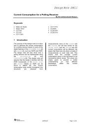
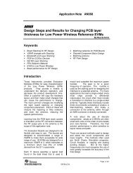
Generic <strong>QTouch</strong> LibrariesIntroductionATMEL <strong>QTouch</strong> provides a simple to use solution to realize touch sensing solutions on a range ofsupported ATMEL AVR Microcontrollers. The <strong>QTouch</strong> libraries provide support for both <strong>QTouch</strong>and QMatrix acquisition methods.Touch sensing using QMatrix or <strong>QTouch</strong> acquisition methods can be added to an application bylinking the appropriate ATMEL <strong>QTouch</strong> <strong>Library</strong> for the AVR Microcontroller and using a simple setof API to define the touch channels and sensors and then calling the touch sensing API’speriodically (or based on application needs) to retrieve the channel information and determinetouch sensor states.Figure 5-1 shows a typical configuration of channels when using an AVR and using the ATMEL<strong>QTouch</strong> <strong>Library</strong>. The ATMEL <strong>QTouch</strong> <strong>Library</strong> has been added to a host application running on anAVR microcontroller. The sample configuration illustrates using the library that supports eighttouch channels numbered 0 to 7. The sensors are configured in the following order,• Sensor 0 on channels 0 to 2 have been configured as a rotor sensor.• Sensor 1 on channels 3 to 5 have been configured as a slider sensor.• Sensor 2 on channel 6 is configured as key sensor.• Sensor 3 on channel 7 is configured as key sensor.The host application uses the <strong>QTouch</strong> <strong>Library</strong> API’s to configure these channels and sensors,and to initiate detection of a touch using capacitive measurements.channel 0channel 1channel 2HostApplication<strong>Atmel</strong> <strong>QTouch</strong><strong>Library</strong>channel 3channel 4sensor1sensor0channel 5channel 6sensor2channel 7sensor3Figure 5-1 : Typical interface of the ATMEL <strong>QTouch</strong> library with the host application.The <strong>QTouch</strong> libraries use minimal resources of the microcontroller. The sampling of the sensorsis controlled by the <strong>QTouch</strong> library, while the sampling period is controlled by the application(possibly using timers, sleep periods, varying the CPU clock, external events like interrupts orcommunications, etc).Acquisition MethodsThere are two methods available for touch acquisition namely1. <strong>QTouch</strong> acquisition method.2. QMatrix acquisition method.13
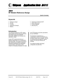
Libraries for AVR microcontrollers include both acquisition methods. Libraries for ATSAMmicrocontrollers include only <strong>QTouch</strong> acquisition method.<strong>QTouch</strong> acquisition methodThe <strong>QTouch</strong> acquisition method charges an electrode of unknown capacitance to a knownpotential. The resulting charge is transferred into a measurement capacitor (Cs). The cycle isrepeated until the voltage across Cs reaches a voltage Vih. The signal level is the number ofcharge transfer cycles it took to reach that voltage. Placing a finger on the touch surfaceintroduces external capacitance that increases the amount of charge transferred each cycle,reducing the total number of cycles required for Cs to reach the voltage. When the signal level(number of cycles) goes below the present threshold, then the sensor is reported to be indetected.<strong>QTouch</strong> acquisition method sensors can drive single or multiple keys. Where multiple keys areused, each key can be set for an individual sensitivity level. Keys of different sizes and shapescan be used to meet both functional and aesthetic requirements.NOTE: It is recommended to keep the size of the keys larger than 6mmx6mm to ensure reliableand robust measurements, although actual key design requirements also depend on panelthickness and material. Refer to the ATMEL Capacitive touch sensor design guide for details.<strong>QTouch</strong> acquisition method can be used in two ways• normal touch contact (i.e. when pressing buttons on a panel), and• high sensitivity proximity mode (i.e. when a panel lights up before you actually contact it).Figure 5-2 : <strong>QTouch</strong> Acquisition<strong>QTouch</strong> circuits offers high signal-to-noise ratio, very good low power performance, and theeasiest sensor layout.Sensor schematics for a <strong>QTouch</strong> acquisition method design148207K-AT42-09/11
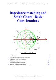
SamplingcapacitorSNSKPB1RsElectrodeMicrocontrollerUsed for touchapplicationCsPC1SNSTypical Rs- 1kvalues: Cs- 22nF----------------Port requirements:SNS: generic I/O pinSNSK: generic I/O pinRs- Series resistor, Cs – Sample capacitor, PB1- PortB bit1, and PC1- PortC bit1Figure 5-3 : Schematics for a <strong>QTouch</strong> acquisition method designQMatrix acquisition methodQMatrix devices detect touch using a scanned passive matrix of electrode sets. A single QMatrixdevice can drive a large number of keys, enabling a very low cost-per-key to be achieved.Figure 5-4 : QMatrix Acquisition methodQMatrix uses a pair of sensing electrodes for each channel. One is an emitting electrode intowhich a charge consisting of logic pulses is driven in burst mode. The other is a receive electrodethat couples to the emitter via the overlying panel dielectric. When a finger touches the panel thefield coupling is changed, and touch is detected. The drive electrode (or drive line) used for15
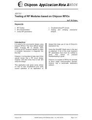
QMatrix charge transfer is labeled as the X line. The receiver electrode (or receive line) used forQMatrix charge transfer is labeled as the Y line.QMatrix circuits offer good immunity to moisture films, extreme levels of temperature stability,superb low power characteristics, and small IC package sizes for a given key count.Sensor schematics for a QMatrix acquisition method design<strong>Atmel</strong> MCUX0RX0Sensor0,0Sensors,X,YSensor0,m...XnRXnSensorn,0Sensorn,mRY0Y0A...YmARYmCS0...CSmY0BYmBTypical values:RX: 1kRY: 1kCS: 4.7nFRYB: 470k----------------------------------Port-pin count =n + (2 * m) + 2SMPVrefRYB0RYBmn – number of X linesm – number of Y lines----------------------------------Port requirements:X: Configurable I/O pinYA:Configurable I/O pin (*)YB: ADC port (*)SMP: Configurable I/O pinVref: AIN0 (Comparator)(*): The port I/O pin shouldbe in consecutive orderFigure 5-5 : Schematics for a QMatrix acquisition method designGlobal settings common to all sensors of a specific acquisition methodThe touch sensing using <strong>QTouch</strong> library could be fine tuned by using a number of configurablesettings. This section explains the settings that are common to all sensors of a specific acquisitionmethod like QMatrix or <strong>QTouch</strong>.For example, if recalibration threshold (one of the global settings) of QMatrix acquisition methodis set as 1, all QMatrix sensors will have recalibration threshold of 1.168207K-AT42-09/11
Recalibration ThresholdRecalibration threshold is the level above which automatic recalibration occurs. Recalibrationthreshold is expressed as a percentage of the detection threshold setting. This setting is anenumerated value and its settings are as follows:• Setting of 0 = 100% of detect threshold (RECAL_100)• Setting of 1 = 50% of detect threshold (RECAL_50)• Setting of 2 = 25% of detect threshold (RECAL_25)• Setting of 3 = 12.5% of detect threshold (RECAL_12_5)• Setting of 4 = 6.25% of detect threshold (RECAL_6_25)However, an absolute value of 4 is the hard limit for this setting. For example, if the detectionthreshold is say, 40 and the Recalibration threshold value is set to 4. This implies an absolutevalue of 2 (40 * 6.25% = 2.5), but this is hard limited to 4.Setting Variable name Data Type Unit Min Max TypicalRecalibration threshold qt_recal_threshold uint8_t Enum 4 Detect 1thresholdDetect IntegrationThe <strong>QTouch</strong> <strong>Library</strong> features a detect integration mechanism, which acts to confirm detection in arobust fashion. The detect integrator (DI) acts as a simple signal filter to suppress false detectionscaused by spurious events like electrical noise.A counter is incremented each time the sensor delta has exceeded its threshold and stayed therefor a specific number of acquisitions, without going below the threshold levels. When this counterreaches a preset limit (the DI value) the sensor is finally declared to be touched. If on anyacquisition the delta is not seen to exceed the threshold level, the counter is cleared and theprocess has to start from the beginning. The DI process is applicable to a ‘release’ (going out ofdetect) event as well.For example, if the DI value is 10, then the device has to exceed its threshold and stay there for10 acquisitions in succession without going below the threshold level, before the sensor isdeclared to be touched.Setting Variable name Data Type Unit Min Max TypicalDI qt_di uint8_t Cycles 0 255 4Drift Hold TimeDrift Hold Time (DHT) is used to restrict drift on all sensors while one or more sensors areactivated. It defines the length of time the drift is halted after a key detection.This feature is useful in cases of high density keypads where touching a key or floating a fingerover the keypad would cause untouched keys to drift, and therefore create a sensitivity shift, andultimately inhibit any touch detection.Setting Variable name Data Type Unit Min Max TypicalDrift hold time qt_drift_hold_time uint8_t 200 ms 1 255 20 (4s)17
Maximum ON DurationIf an object unintentionally contacts a sensor resulting in a touch detection for a prolonged intervalit is usually desirable to recalibrate the sensor in order to restore its function, perhaps after a timedelay of some seconds.The Maximum on Duration timer monitors such detections; if detection exceeds the timer’ssettings, the sensor is automatically recalibrated. After a recalibration has taken place, theaffected sensor once again functions normally even if it still in contact with the foreign object.Max on duration can be disabled by setting it to zero (infinite timeout) in which case the channelnever recalibrates during a continuous detection (but the host could still command it).Setting Variable name Data Type Unit Min Max TypicalMaximum ON Duration qt_max_on_duration uint8_t 200 ms 0 255 30 (6s)Positive / Negative DriftDrift in a general sense means adjusting reference level (of a sensor) to allow compensation fortemperature (or other factor) effect on physical sensor characteristics. Decreasing reference levelfor such compensation is called Negative drift & increasing reference level is called Positive drift.Specifically, the drift compensation should be set to compensate faster for increasing signals thanfor decreasing signals.Signals can drift because of changes in physical sensor characteristics over time andtemperature. It is crucial that such drift be compensated for; otherwise false detections andsensitivity shifts can occur.Drift compensation occurs only while there is no detection in effect. Once a finger is sensed, thedrift compensation mechanism ceases since the signal is legitimately detecting an object. Driftcompensation works only when the signal in question has not crossed the ‘Detect threshold’ level.The drift compensation mechanism can be asymmetric; it can be made to occur in one directionfaster than it does in the other simply by changing the appropriate setup parameters.Signal values of a sensor tend to decrease when an object (touch) is approaching it or acharacteristic change of sensor over time and temperature. Decreasing signals should not becompensated for quickly, as an approaching finger could be compensated for partially or entirelybefore even touching the channel (negative drift).However, an object over the channel which does not cause detection, and for which the sensorhas already made full allowance (over some period of time), could suddenly be removed leavingthe sensor with an artificially suppressed reference level and thus become insensitive to touch. Inthe latter case, the sensor should compensate for the object’s removal by raising the referencelevel relatively quickly (positive drift).Setting Variable name Data Type Unit Min Max TypicalNegative Drift qt_neg_drift_rate uint8_t 200 ms 1 127 20 (4s)Positive Drift qt_pos_drift_rate uint8_t 200 ms 1 127 5 (1s)Positive Recalibration Delay188207K-AT42-09/11
If any key is found to have a significant drop in signal delta, (on the negative side), it is deemed tobe an error condition. If this condition persists for more than the positive recalibration delay, i.e.,qt_pos_recal_delay period, then an automatic recalibration is carried out.A counter is incremented each time the sensor delta is equal to the positive recalibrationthreshold and stayed there for a specific number of acquisitions. When this counter reaches apreset limit (the PRD value) the sensor is finally recalibrated. If on any acquisition the delta isseen to be greater than the positive recalibration threshold level, the counter is cleared and thepositive drifting is performed.For example, if the PRD value is 10, then the delta has to drop below the recalibration thresholdand stay there for 10 acquisitions in succession without going below the threshold level, beforethe sensor is declared to be recalibrated.Setting Variable name Data Type Unit Min Max TypicalPositiveRecalibrationDelayqt_pos_recal_delay uint8_t cycles 1 255 3Sensor specific settingsApart from global settings as mentioned in the section above, touch sensing using <strong>QTouch</strong> librarycould also be fine tuned by more number of configurable settings.This section explains the settings that are specific to each sensor. For example, sensor 0 canhave a detect threshold (one of the sensor specific setting) that is different from sensor 1.Detect thresholdA sensor’s negative (detect) threshold defines how much its signal must drop below its referencelevel to qualify as a potential touch detect. The final detection confirmation must however satisfythe Detect Integrator (DI) limit. Larger threshold values desensitize sensors since the signal mustchange more (i.e. requires larger touch) in order to exceed the threshold level. Conversely, lowerthreshold levels make sensors more sensitive.Threshold setting depends on the amount of signal swing that occurs when a sensor is touched.Thicker front panels or smaller electrodes usually have smaller signal swing on touch, thusrequire lower threshold levels.Setting Variable name Data Type Unit Min Max TypicalThreshold threshold uint8_t counts 3 255 10 – 20HysteresisThis setting is sensor detection hysteresis value. It is expressed as a percentage of the sensordetection threshold setting. Once a sensor goes into detect its threshold level is reduced (by thehysteresis value) in order to avoid the sensor dither in and out of detect if the signal level is closeto original threshold level.• Setting of 0 = 50% of detect threshold value (HYST_50)• Setting of 1 = 25% of detect threshold value (HYST_25)• Setting of 2 = 12.5% of detect threshold value (HYST_12_5)• Setting of 3 = 6.25% of detect threshold value (HYST_6_25)19
Setting Variable name Data Type Unit Min Max TypicalHysteresis detect_hysteresis uint8_t (2 bits) Enum HYST_6_25 HYST_50 HYST_6_25Position ResolutionThe rotor or slider needs the position resolution (angle resolution in case of rotor and linearresolution in case of slider) to be set. Resolution is the number of bits needed to report theposition of rotor or slider. It can have values from 2bits to 8 bits.SettingPositionResolutionVariablenameposition_resolutionDataTypeuint8_t(3 bits)Unit Min Reported Max Reported Typicapositionposition l- 2 bits 0 – 3 8 bits 0-255 8Position HysteresisIn case of QMatrix, the rotor or slider needs the position hysteresis (angle hysteresis in case ofrotor and linear hysteresis in case of slider) to be set. It is the number of positions the user has tomove back, before touch position is reported when the direction of scrolling is changed andduring the first scrolling after the touch down.Hysteresis can range from 0 (1 position) to 7 ( 8 positions). The hysteresis is carried out at 8 bitsresolution internally and scaled to desired resolution; therefore at resolutions lower than 8 bitsthere might be a difference of 1 reported position from the hysteresis setting, depending on wherethe touch is detected.At lower resolutions, where skipping of the reported positions is observed, hysteresis can be setto 0 (1 position). At Higher resolutions (6 ..8bits) , it would be recommended to have a hysteresisof at least 2 positions or more.NOTE:It is not valid to have a hysteresis value more than the available bit positions in the resolution.Ex: do not have a hysteresis value of 5 positions with a resolution of 2 bits (4 positions).Setting Variable name Data Type Unit Min Max TypicalPosition position_hysteresis uint8_t (3 bits) - 0 7 3HysteresisNOTE:Position hysteresis is not valid (unused) in case of <strong>QTouch</strong> acquisition method libraries.Adjacent Key Suppression (AKS)In designs where the sensors are close together or set for high sensitivity, multiple sensors mightreport detect simultaneously if touch is near them. To allow applications to determine theintended single touch, the touch library provides the user the ability to configure a certain numberof sensors in an AKS group.When a group of sensors are in the same AKS group, then only the first strongest sensor willreport detection. The sensor reporting detection will continue to report detection even if anothersensor’s delta becomes stronger. The sensor stays in detect until its delta falls below its detectionthreshold, and then if any more sensors in the AKS group are still in detect then the strongest will208207K-AT42-09/11
eport detection. So at any given time only one sensor from each AKS group will be reported tobe in detect.The library provides the ability to configure any sensor to be included in any one of the AdjacentKey Suppression Groups (AKS Group).Setting Variable name Data Type Unit Min Max TypicalAKS Group aks_group uint8_t (3 bits) Enum 0 (off) 7 0 (off)Using the SensorsAvoiding Cross-talkIn ATMEL <strong>QTouch</strong> library variants that use <strong>QTouch</strong> acquisition technology, adjacent sensors arenot measured at the same time. This prevents interference due to cross-talk between adjacentchannels, but at the same time some sensor configurations take longer to measure than others.For example, if an 8-channel device is configured to support 8 keys, then the library will measurethe keys on channels 0, 2, 4, and 6 parallely, followed by keys on channels 1, 3, 5, and 7. If thesame device is configured, say, to support 4 keys, putting them either on all the odd channels oron all the even channels means that they can all be measured simultaneously.This means the library calls are faster, and the device can use less power. So, it is recommendedthat the appropriate channel numbers are used when using less than the maximum number ofchannels available for the device to ensure optimum performance. In a similar sense for fasterexecution and reduced power consumption, it is also advisable to use intra-port sensorconfiguration instead of inter-port sensor configuration while using 4 channels on the same port.Multiple measurementsThe library will not automatically perform multiple measurements on a sensor (Ex: To resolve forinstance Detect Integration or recalibration.). The user is given the option to perform themeasurement multiple times if certain conditions are met. This will enable the user to implementthe time critical code thereby making the qt_measure_sensors() a non-blocking API .The hostapplication has to perform multiple measurements, based on the need. The global flagQTLIB_BURST_AGAIN indicating that multiple measurements are needed is passed to the user.This is BIT8 of the return value from the qt_measure_sensors( ) API. The main_.chas the example usage to perform multiple measurements.If QTLIB_BURST_AGAIN = 1, multiple measurements are needed to‣ To compensate for drift‣ Resolve re-calibration‣ Resolve calibration.‣ Resolve detect integration.If QTLIB_BURST_AGAIN = 0, multiple measurements are not needed and the user can executethe host application code. Apart from QTLIB_BURST_AGAIN, various flags are provided to theuser to perform the multiple measurements based on the need of the host application to act tospecific situation. Description of the these flags can be found in the section5.6.5.6Note: To maintain robustness and timing of the touch sensing measurement, it is recommendedthat the user calls the qt_measure_sensors() immediately if the flag QT_BURST_AGAIN=1.However, the user is allowed to run time- critical section (not more than few instructions) of thehost application comprising on the touch sensing timing.21
Guard ChannelGuard channel in Qtouch Acquisition Method allows one key to be configured as a guard channelto help prevent false detection. Guard channel keys should be more sensitive than the other keys(physically bigger or larger Cs).To enable key as guard channel, the designated key is connectedto a sensor pad which detects the presence of touch and overrides any output from the otherkeys using the AKS feature.The key can be configured to have a guard channel function by adjusting a number ofindependent settings. The Guard channel is designed so that it is likely to be activated unless akey is accurately touched.The guard channel sensor must be set up so that it is slightly more sensitive than the keys that itsurrounds. The exact amount of increase depends on the application and is best determined byexperimentation.There are three methods of increasing the sensor sensitivity that can be used in combination:1. Increasing the size of the sensor.2. Increasing the value of the Sample Capacitor (Cs).3. Adjust the detection threshold for the sensor.The sensor size and capacitor values should be altered to establish the base sensitivity for thesensor. Once these values have been established, the detection threshold can be used to finetune the sensor.MCU withSNS andSNSKPinsThe Above figure illustrates how a Guard sensor/key is to be visualized.It has six keys and fivekeys are surrounded by a Guard Channel.Please refer QTAN0031 for further information on Guard Channel.http://www.atmel.com/dyn/resources/prod_documents/QTAN0031(2).pdf228207K-AT42-09/11
<strong>QTouch</strong> API and UsageThe <strong>Atmel</strong> <strong>QTouch</strong> library provides support for many devices. This chapter explains the touchlibrary for such devices without any hardware support.<strong>QTouch</strong> <strong>Library</strong> APIThis section describes the <strong>QTouch</strong> library Application Programming Interface (API) for touchsensing using <strong>QTouch</strong> and QMatrix acquisition methods.Using the API, Touch sensors and the associated channels can be defined. Once touch sensinghas been initiated by the user, the host application can use the API to make touch measurementsand determine the status of the sensors.touch_api.h - public header fileThe touch_api.h header file is the public header file which needs to be included in usersapplication and it has the type definitions and function prototypes of the API’s listed in sections5.6.3 , 5.6.4 and 5.6.5The touch_api.h header file is located in the library distribution in the following directory.• ..\<strong>Atmel</strong>_<strong>QTouch</strong>_Libraries_4.x\Generic_<strong>QTouch</strong>_Libraries\includeType Definitions and enumerations used in the libraryTypedefsThis section lists the type definitions used in the library.Typedef Notesuint8_t unsigned 8-bit integerint8_t signed 8-bit integeruint16_t unsigned 16-bit integerint16_t signed 16-bit integeruint32_t unsigned 32-bit integerthreshold_t unsigned 8-bit integerused for setting a sensor detection thresholdEnumerationsThis section lists the enumerations used in the <strong>QTouch</strong> <strong>Library</strong>.sensor_type_tEnumerationUsesensor_type_tDefine the type of the sensorValuesSENSOR_TYPE_UNASSIGNEDSENSOR_TYPE_KEYSENSOR_TYPE_ROTORSENSOR_TYPE_SLIDERCommentChannel is not assigned to any sensorSensor is of type KEYSensor is of type ROTORSensor is of type SLIDERaks_group_tEnumerationUseaks_group_tDefines the Adjacent Key Suppression (AKS) groups each sensor may beassociated with ( see section 5.3.4 Maximum ON Duration)AKS is selectable by the system designer23
7 AKS groups are supported by the libraryValuesCommentNO_AKS_GROUP NO AKS group selected for the sensorAKS_GROUP_1 AKS Group number 1AKS_GROUP_2 AKS Group number 2AKS_GROUP_3 AKS Group number 3AKS_GROUP_4 AKS Group number 4AKS_GROUP_5 AKS Group number 5AKS_GROUP_6 AKS Group number 6AKS_GROUP_7 AKS Group number 7channel_tEnumerationUsechannel_tThe channel numbers used in the library.When using the <strong>QTouch</strong> acquisition method, the channel numbers have a oneto one mapping to the pin numbers of the port being used.When using the QMatrix acquisition method, the channel numbers are orderedin a matrix sequenceValuesCommentCHANNEL_0 Channel number : 0CHANNEL_1 Channel number : 1CHANNEL_2 Channel number : 2CHANNEL_3 Channel number : 3..... Channel number: ..Upto CHANNEL ( N-1 ) Channel number N-1 : for an N Channel libraryThe maximum number of channels supported is dependent on the library variant. Possible valuesof N are as listed belowAcquisition method Device type Possible values of N( Maximum number of channels )<strong>QTouch</strong> acquisition 8-bit 4,8,1632-bit 8, 16, 32QMatrix Acquisition 8-bit 8,16,32,64hysteresis_tEnumerationUseHysteresis_tDefines the sensor detection hysteresis value. This is expressed as apercentage of the sensor detection threshold.This is configurable per sensor.HYST_x = hysteresis value is x percent of detection threshold value (roundeddown).Note that a minimum value of 2 is used as a hard limit. Example: if detectionthreshold = 20, then:HYST_50 = 10 (50 percent of 20)HYST_25 = 5 (25 percent of 20)HYST_12_5 = 2 (12.5 percent of 20)HYST_6_25 = 2 (6.25 percent of 20 = 1, but set to the hard limit of 2)248207K-AT42-09/11
ValuesHYST_50HYST_25HYST_12_5HYST_6_25Comment50% Hysteresis25% Hysteresis12.5% Hysteresis6.25% Hysteresisresolution_tEnumeration<strong>User</strong>esolution_tFor rotors and sliders, the resolution of the reported angle or position.RES_x_BIT = rotor/slider reports x-bit values.Example: if slider resolution is RES_7_BIT, then reported positions are in therange 0…127.Values CommentRES_1_BIT 1 bit resolution : reported positions range 0 – 1RES_2_BIT 2 bit resolution : reported positions range 0 – 3RES_3_BIT 3 bit resolution : reported positions range 0 – 7RES_4_BIT 4 bit resolution : reported positions range 0 – 15RES_5_BIT 5 bit resolution : reported positions range 0 – 31RES_6_BIT 6 bit resolution : reported positions range 0 – 63RES_7_BIT 7 bit resolution : reported positions range 0 – 127RES_8_BIT 8 bit resolution : reported positions range 0 – 255recal_threshold_tEnumeration<strong>User</strong>ecal_threshold_tA sensor recalibration threshold. This is expressed as a percentage of thesensor detection threshold.This is for automatic recovery from false conditions, such as a calibration whilesensors were touched, or a significant step change in power supply voltage.If the false condition persists the library will recalibrate according to the settingsof the recalibration threshold.This setting is applicable to all the configured sensors.Usage :RECAL_x = recalibration threshold is x percent of detection threshold value(rounded down).Note: a minimum value of 4 is used.Example: if detection threshold = 40, then:RECAL_100 = 40 ( 100 percent of 40)RECAL_50 = 20 ( 50 percent of 40)RECAL_25 = 10 ( 25 percent of 40)RECAL_12_5 = 5 ( 12.5 percent of 40)RECAL_6_25 = 4 ( 6.25 percent of 40 = 2, but value is limited to 4)ValuesRECAL_100RECAL_50RECAL_25RECAL_12_5RECAL_6_25Comment100% recalibration threshold50% recalibration threshold25% recalibration threshold12.5% recalibration threshold6.25% recalibration threshold25
Data structuresThis section lists the data structures that hold sensor status, settings, and diagnostics informationqt_touch_status_tStructure qt_touch_status_tInput / Output Output from the <strong>Library</strong>UseHolds the status ( On/ Off ) of the sensors and the linear and angular positionsof sliders and rotors respectivelyFieldsCommentsensor_states[] For Sensor, the sensor_states. Bit “n” = state of nth sensor :Bit Value 0 - indicates the sensor is not in detectBit Value 1 - indicates the sensor is in detectrotor_slider_values[]Rotors angles or slider positions if rotors and sliders are used. Thesevalues are valid when sensor states shows that the corresponding rotor orslider is in detectThe macro that can get the sensor state when the sensor number is provided can be somethingas below:#define GET_SENSOR_STATE(SENSOR_NUMBER)qt_measure_data.qt_touch_status.sensor_states[(SENSOR_NUMBER/8)] &(1
section 5.3.2 Detect Integration for more detailsqt_drift_hold_time uint8_t Sensor drift hold time in units of 200 ms. Default value: 20 (20 x200 ms = 4s), that is hold off drifting for 4 seconds after leavingdetect. Refer to section 5.3.3 Drift Hold Time for more detailsqt_max_on_duration uint8_t Sensor maximum on duration in units of 200 ms. For example:150 = recalibrate after 30s (150 x 200 ms). 0 = recalibrationdisabled Default value: 0 (recalibration disabled). Refer tosection 5.3.4 Maximum ON Duration for more details.qt_neg_drift_rate uint8_t Sensor negative drift rate in units of 200 ms. Default value: 20(20 x 200 ms = 4s per LSB). Refer to section 5.3.5 Positive /Negative Drift for more detailsqt_pos_drift_rate uint8_t Sensor positive drift rate in units of 200 ms. Default value: 5 (5 x200 ms = 1s per LSB). Refer to section 5.3.5 Positive / NegativeDrift for more detailsqt_pos_recal_delay uint8_t Sensor positive recalibration delay. Default: 3. Refer to section5.3.6 for more details.The measurement limit for touch sensing using <strong>QTouch</strong> acquisition method is hard coded as8192.The <strong>QTouch</strong> library exports a variable of this type so that the user can specify the thresholdparameters for the library. The API qt_set_parameters() should be called to apply the parametersspecified.extern qt_touch_lib_config_data_t qt_config_data;qt_touch_lib_measure_data_tStructure qt_touch_lib_measure_data_tInput / Output Output from the libraryUseData structure which holds the sensor and channel states and values.Fields Type Commentchannel_signals uint16_t The measured signal on each channel.channel_references uint16_t The reference signal for each channel.qt_touch_status qt_touch_status_t The state and position of the configured sensorsThe <strong>QTouch</strong> library exports a variable of this type which can be accessed to retrieve the touchstatus of all the sensors.extern qt_touch_lib_measure_data_t qt_measure_data;qt_burst_lengthsStructureInput / OutputUseqt_burst_lengthsInput to the libraryNOTE: Applicable only to the QMatrix acquisition method librariesThis data structure is used to specify the burst lengths for each of the QMatrixchannelsFields Type Commentqt_burst_lengths[] uint8_t The burst length for each of the QMatrix channel in units of pulses. Defaultvalue: 64 pulses.These values can be configured for each channel individually.27
The signal gain for each sensor is controlled by circuit parameters as well as the burst length.The burst length is simply the number of times the charge-transfer (‘QT’) process is performed ona given sensor. Each QT process is simply the pulsing of an X line once, with a corresponding Yline enabled to capture the resulting charge passed through the sensor’s capacitance Cx.The QMatrix acquisition method library exports a variable of this type which can be accessed toset the burst length for each of the QMatrix channelsextern uint8_t qt_burst_lengths[QT_NUM_CHANNELS];tag_sensor_tStructureInput / OutputUsetag_sensor_tOutput from the libraryData structure which holds the internal sensor state variables used by thelibrary.Fields Type CommentState uint8_t internal sensor stategeneral_counter uint8_t general purpose counter: used for calibration, drifting, etcndil_counter uint8_t drift Integration counterThreshold uint8_t sensor detection threshold. Refer to section 5.4.1 Detect threshold for moredetailstype_aks_pos_hyst uint8_t holds information for sensor type, AKS group, positive recalibration flag, andhysteresis valueBit fields UseB1 : B0Hysteresis. Refer to section 5.4.2 Hysteresis for moredetailsB2positive recalibration flagB5:B3AKS group. Refer to section 5.4.5 for more detailsB7:B6sensor typefrom_channel uint8_t starting channel number for sensorto_channel uint8_t ending channel number for sensorIndex uint8_t index for array of rotor/slider valuesqt_lib_siginfo_tStructureInput / OutputUseqt_lib_siginfo_tOutput from the libraryData structure which holds the information about the library variant and itsversion information.qt_lib_siginfo_t structure definition for a <strong>QTouch</strong> acquisition method library variantFields Type Commentlibrary_version uint16_t Holds the library version information.Bit fieldsUseB3 : B0Patch version of the libraryB7 : B4Minor version of the libraryB15:B8Major version of the librarylib_sig_lword uint16_t Holds the general information about the libraryBit fieldsUseB1 : B0 <strong>Library</strong> Type :00 : <strong>QTouch</strong> acquisition method01 : QMatrix acquisition methodB2Compiler tool chain used288207K-AT42-09/11
B9 : B3B10B15 : B11lib_sig_hword uint16_t Reserved0 – GCC1 – IARMaximum number of channelssupported by the library0 – <strong>Library</strong> supports only keys1 – <strong>Library</strong> supports keys androtorsMaximum number of rotors andsliders supported by the libraryqt_lib_siginfo_t structure definitions for a QMatrix acquisition method library variantFields Type Commentlibrary_version uint16_t Holds the library version information.Bit fieldsUseB3 : B0Patch version of the libraryB7 : B4Minor version of the libraryB15:B8Major version of the librarylib_sig_lword uint16_t Holds the general information about the libraryBit fieldsUseB1 : B0 <strong>Library</strong> Type :00 : <strong>QTouch</strong> acquisition method01 : QMatrix acquisition methodB2Compiler tool chain used0 – GCC1 – IARB9 : B3Maximum number of channelssupported by the libraryB100 – <strong>Library</strong> supports only keys1 – <strong>Library</strong> supports keys androtorsB15 : B11Maximum number of rotors andsliders supported by the librarylib_sig_hword uint16_t Holds information about the X and Y lines for a QMatrix library variantBit fieldsUseB4 : B0Number of X LinesB8 : B5Number of Y LinesB9 0Public FunctionsThis section lists the public functions available in the <strong>QTouch</strong> libraries and its usage.qt_set_parametersThis function is used to initialize the global configuration settings in the variableqt_config_data of the <strong>QTouch</strong> and QMatrix acquisition method libraries.void qt_set_parameters ( void )Arguments Type CommentVoid - This function will initialize the parameters required by the library to default values .Butthe default values can be changed by the user by modifying the global thresholdvalues as defined in qt_touch_lib_config_data_t . See section 0 for details.NOTE:29
• This function can be called any time to apply the threshold parameters of the library asspecified by modifying the global data structure qt_config_data exported by the library.qt_enable_keyThis function is used to configure a channel as a key.void qt_enable_key (channel_t channel ,aks_group_t aks_group ,threshold_t detect_threshold ,hysteresis_t detect_hysteresis)Arguments Type CommentChannel channel_t Specifies the channel number to be configured for use as a “key”aks_group aks_group Specifies the aks group associated with the sensor being configured as“key”detect_threshold threshold_t Specifies the detect threshold for the sensordetect_hysteresis hysteresis_t Specifies the detection hysteresis for the sensorqt_enable_rotorThis function is used to configure a set of channels as a rotor.void qt_enable_rotor (channel_t from_channel ,channel_t to_channel ,aks_group_t aks_group ,threshold_t detect_threshold ,hysterisis_t detect_hysterisis ,resoulution_t angle_resolution ,uint8_tangle_hysterisis)Arguments Type Commentfrom_channel Channel_t Specifies the starting channel number to be configured for use as a “Rotor”to_channel Channel_t Specifies the end channel number to be configured for use as a “Rotor”aks_group aks_group Specifies the aks group associated with the sensor being configured as“ROTOR”detect_threshold threshold_t Specifies the detect threshold for the sensordetect_hysterisis hysterisis_t Specifies the detection hysteresis for the sensorangle_resolution resolution_t Specifies the resolution of the reported angle valueangle_hysterisis uint8_t Specifies the hysteresis of the reported angle valueNOTE:• A “Rotor” sensor requires contiguous channel numbers.• The rotor / slider number depends on the order in which the rotor or sliders are enabled.The first rotor or slider enabled will use “rotor_slider_values[0]”, the second will use“rotor_slider_values[1]”, and so on. The reported rotor value is valid when the rotor isreported as being in detect.• In case of QMatrix acquisition method library, the from_channel and to_channel can bebetween 3 to 8 channel numbers apart (i.e. it can support 3 to 8 channel rotors).• In case of <strong>QTouch</strong> acquisition method library, the from_channel and to_channel can be 3channels apart (i.e. can support only 3 channel rotors).308207K-AT42-09/11
qt_enable_sliderThis function is used to configure a set of channels as a rotor.void qt_enable_slider (channel_t from_channel ,channel_t to_channel ,aks_group_t aks_group ,threshold_t detect_threshold ,hysterisis_t detect_hysterisis ,resolution_t position_resolution ,uint8_tposition_hysteresis)Arguments Type Commentfrom_channel Channel_t Specifies the starting channel number to be configured for use as a“Slider”to_channel Channel_t Specifies the end channel number to be configured for use as a “Slider”aks_group aks_group Specifies the aks group associated with the sensor being configured as“Slider”detect_threshold threshold_t Specifies the detect threshold for the sensordetect_hysterisis hysterisis_t Specifies the detection hysteresis for the sensorposition_resolution resolution_t Specifies the resolution of the reported position valueposition_hysterisis uint8_t Specifies the hysteresis of the reported position valueNOTE:• A “Slider” sensor requires a contiguous numbers of channels.• The rotor / slider number depends on the order in which the rotor or sliders are enabled.The first rotor or slider enabled will use “rotor_slider_values[0]”, the second will use.“rotor_slider_values[1]”, and so on. The reported rotor value is valid when the slider isreported as being in detect.• In case of QMatrix acquisition method library, the from_channel and to_channel can bebetween 3 to 8 channels apart (i.e. it can support 3 to 8 channel sliders).• In case of <strong>QTouch</strong> acquisition method library, the from_channel and to_channel can be 3channels apart (i.e. can support only 3 channel sliders).qt_init_sensingThis function is used to initialize the touch sensing for all enabled channels. All required sensorsshould be configured before calling this function.void qt_init_sensing ( void )Arguments Type CommentVoid - -NOTE:• All sensors must be configured (using qt_enable_key, qt_enable_rotor orqt_enable_slider ) before calling this function.• This functions initializes all the configured sensors, performs calibration.qt_measure_sensorsThis function performs a capacitive measurement on all enabled sensors. The measured signalsfor each sensor are then processed to check for user touches, releases, changes in rotor angleand changes in slider position.31
unit16_t qt_measure_sensors( uint16_t current_time_ms )Arguments Type Commentcurrent_time_ms uint16 The current time in millisecondsReturnValueuint16_tCommentReturns the status of the <strong>Library</strong> as a combination of the following bit fields.Return valueBit CommentsdefinitionQTLIB_NO_ACTIVITY 0x0000 No activity detected on any of thesensorsQTLIB_IN_DETECT 0x0001 At least one sensor is in detectQTLIB_STATUS_CHANGE 0x0002 At least one sensor has changedON/OFF state since the last call toqt_measure_sensor()QTLIB_ROTOR_SLIDER_POS_CHANGE 0x0004 At least one rotor/slider has changedposition since the last call toqt_measure_sensors()QTLIB_CHANNEL_REF_CHANGE 0x0008 At least one reference value haschanged since last call toqt_measure_sensors()QTLIB_BURST_AGAIN 0x0100 Flag to indicate Multiple measurementsneeded.QTLIB_RESOLVE_CAL 0x0200 Multiple measurements needed toresolve calibration. Callqt_measure_sensors( ) once again.QTLIB_RESOLVE_FILTERIN 0x0400 Multiple measurements needed toresolve filtering. Callqt_measure_sensors( ) once again.QTLIB_RESOLVE_DI 0x0800 Multiple measurements needed toresolve detect integration. Callqt_measure_sensors( ) once again.QTLIB_RESOLVE_POS_RECAL 0x1000 Multiple measurements needed toresolve positive recalibration. Callqt_measure_sensors( ) once again.NOTE:• All sensors must be configured (using qt_enable_key or qt_enable_rotor orqt_enable_slider) and initialized by calling qt_init_sensing before calling this function.qt_calibrate_sensingThis function forces a recalibration of all enabled sensors.void qt_calibrate_sensing( void )Arguments Type CommentVoid - -NOTE:• Recalibration may be useful if, for example, it is desired to globally recalibrate all sensorson a change in application operating mode.• This function must be called only when the sensors have been configured and initialized.328207K-AT42-09/11
qt_reset_sensingThis function disables all sensors and resets all configuration settings (for example, “qt_di”) totheir default values.void qt_reset_sensing( void )Arguments Type CommentVoid - -NOTE:• This may be useful if it is desired to dynamically reconfigure sensing. After calling thisfunction, any required sensors must be re-enabled, filter callback needs to be reinitialized,and “qt_init_sensing()” must be called before “qt_measure_sensors()” is calledagain.• In case of QMatrix, the burst lengths for all channels are set to zero.qt_get_sensor_deltaThis function returns the delta value for a given channel.int16_t qt_get_sensor_delta( uint8_t sensor_number )Arguments Type Commentsensor_number unit8_t sensor id for which the delta is requiredReturn typeint16_tCommentThe delta value of the sensor specifiedNOTE:• All sensors must be configured (using qt_enable_key or qt_enable_rotor orqt_enable_slider) and initialized by calling qt_init_sensing before calling this function.qt_get_library_sigThis function is used to retrieve the library version and signature from the library.void qt_get_library_sig( qt_lib_siginfo_t *lib_sig_ptr )Arguments Type Commentlib_sig_ptr qt_lib_siginfo_t * Pointer to the structure which needs to beupdated with the library signatureinformationNOTE:• The function qt_measure_sensors() should have been called at least once prior to callingthis function.Sequence of Operations and Using the APIFigure 6 illustrates the sequence of operations required to be performed to add touch to an endapplication. By using the simple API’s as illustrated in the sequence flowchart, the user can addtouch sensing in his design.33
Channel NumberingChannel numbering when using <strong>QTouch</strong> acquisition method<strong>QTouch</strong> acquisition method libraries require 2 GPIO pins per channel. <strong>QTouch</strong> libraries can beconfigured to use 1 to 16 channels requiring 2 to 32 pins respectively. There are two optionsprovided for connecting the SNS and SNSK pins.1. The SNS and SNSK pins are connected to separate ports. ( i.e. Interport)2. The SNS and SNSK pins are connected to the same port. ( i.e. Intraport)The following list provides a look at various combinations supported by various 8bit AVRlibraries released for each device.When pin configurability is not used:• 4-channel library – supports up to 4 channels using 4 consecutive pins on different SNSand SNSK ports (or) supports up to 4 channels using 8 consecutive pins on the sameport used for both SNS and SNSK lines. This library requires 1 or 2 ports.• 8-channel library – supports up to 8 channels using 8 consecutive pins on different SNSand SNSK ports (or) supports up to 8 channels using 16 pins spread over two ports (SNSand SNSK are on alternate pins) with SNS1 and SNSK1 pins on the first port and SNS2and SNSK2 pins on the second port. This library requires 2 ports.• 12-channel library (available only for 8bit AVR devices) – supports up to 12 channels outof which, 8 channels with 8 consecutive pins for SNS1 and SNSK1 are available ondifferent ports and the other 4 channels with 8 consecutive pins available on the sameport for both SNS and SNSK lines. This library requires a total of 3 ports.• 16-channel library – supports up to 16 channels out of which, 8 channels with 8consecutive pins for SNS1 and SNSK1 are available on different ports and the other 8channels with 8 consecutive pins are available on a different pair of SNS2 and SNSK2ports. This library requires a total of 4 ports.When pin configurability is used:• 4-channel library – supports up to 4 channels using any 4 pins on different SNS andSNSK ports (or) supports up to 4 channels using pins on the same port used for bothSNS and SNSK lines. This library requires 1 or 2 ports.• 8-channel library – supports up to 8 channels using 8 pins on different SNS and SNSKports (or) supports up to 8 channels using pins spread over two ports (SNS and SNSKare on alternate pins) with SNS1 and SNSK1 pins on the first port and SNS2 and SNSK2pins on the second port. This library requires 2 ports.• 12-channel library (available only for 8bit AVR devices) – supports up to 12 channels outof which, 8 channels with 8 pins for SNS1 and SNSK1 are available on different ports andthe other 4 channels with 8 pins available on the same port for both SNS and SNSKlines. This library requires a total of 3 ports.• 16-channel library – supports up to 16 channels out of which, 8 channels with 8 pins forSNS1 and SNSK1 are available on different ports and the other 8 channels with 8 pinsare available on a different pair of SNS2 and SNSK2 ports. This library requires a total of4 ports.Note:‣ When a library supports 4 channels using 8 consecutive pins on the same port, the SNS andSNSK pins are allocated alternately. This is valid for all the libraries mentioned above.348207K-AT42-09/11
‣ Usage of intraport configuration requires more code memory than the interport configuration.The values mentioned in the <strong>Library</strong>_selection_<strong>Guide</strong>.xls are for interport configurations. Thememory consumption for intra-port will be higher to the values mentioned in the<strong>Library</strong>_selection_<strong>Guide</strong>.xls‣ The configurations on pin configurability should be used in conjunction with the rules forassigning the pins that are described in section 5.8.2For UC3 and ATSAM libraries, an n- channel library supports up to n channels using nconsecutive pins on different SNS and SNSK ports (or) supports up to n/2 channels using (n)consecutive pins on the same port used for both SNS and SNSK lines. This library requires 1 or 2UC3 or ATSAM ports. In addition to this, for the ATSAM libraries the pins can be configured on 3ports based on the configuration selected.NOTE:Some of the devices in UC3 family has ports having more than 32 pins or less than 32pins.In those devices, the mapping is given as below:GPIO Port0 -> AGPIO Port1 -> BGPIO Port2 -> CGPIO Port3 -> XExample SNS=A and SNSK=X, So channel 0 will be (SNS0 = GPIO0_Pin0 and SNSK0 =GPIO3_Pin0 ).Similarly,Example SNS=X and SNSK=X, So channel 0 will be (SNS0 = GPIO3_Pin0 and SNSK0= GPIO3_Pin1 ).35
qt_reset_sensing()qt_enable_xxx()qt_init_sensing()qt_set_parameters()init_timer_isr()The host application (optionally) calls “qt_reset_sensing( )”to reset all channels and touch sensing parameters to theirdefault states. This step is only required if the host wants todynamically reconfigure the library at runtimeThe host application calls “qt_enable_key( )”, “qt_enable_rotor( )”and/or “qt_enable_slider()” as required to configure the touchsensorsThe host application calls qt_init_sensing() to calibrate all theconfigured channels and prepare the sensors for capacitivemeasurementThe host application qt_set_parameters() to initialize the thresholdparameters for the library. If the user needs to change the thresholds,edit the global data structure qt_config_data prior to calling this APIThe host application initializes the timer module required forcapacitive measurementqt_measure_sensors()The host application periodically calls“qt_measure_sensors( )” to make capacitive measurements.YesTime-critical hostapplication codePart of host applicationwhich cannot wait till multiplemeasurements are complete (shouldbe as minimal as possible)IsQTLIB_BURST_AGAIN=1NoCheck if multiple measurements are needed or not:To resolve calibrationTo resolve DITo resolve positive recalibrationTo compensate for driftcheck qt_touch_statusNon-Time critical host application codecheck the global status variable “qt_touch_status” to see if anysensors are in detect, and the angle or position of any enabledrotors or slidersHost application which can be executed afterthe completion of multiple measurementsfor all the channelsFigure 5-6: Sequence of operations to add Touch capability368207K-AT42-09/11
Channel numbering when routing SNS and SNSK pins todifferent portsFigure 5-7 illustrates a sample <strong>QTouch</strong> capacitive sensing solution which uses four ports (twoport pairs ) on a device for routing the SNS and SNSK lines required.When SNS and SNSK pins are available on different ports, the channel numbering follows the pinnumbering in the ports selected, when pin configurability is not used.• The channel numbers follow the pin numbers starting with the LSB (pin 0 is channel 0and pin 7 is channel 7).• When a library on corresponding device is configured to use more than two ports for SNSand SNSK pins, the channel numbers in the second set of SNS/SNSK port pair continuefrom the preceding pair as illustrated in Figure 5-7(pin 0 of next port pair is channel 8 andpin 7 of the next port pair is channel 15).• Support for more than one pair of SNS and SNSK ports are not available for UC3devices.• SNS pins within a single port and SNSK pins within another single port can only be usedas channels for slider/rotor. Slider/Rotor channels cannot share SNS/SNSK pins ondifferent ports.• Since the channel numbers are fixed to the pins of the SNS and SNSK ports, if thedesign calls for use of a subset of the pins available in the SNS and SNSK ports, the userhas to skip the channel numbers of the unused SNS and SNSK pins.o For example, on a 8 channel configuration using a single pair of SNS and SNSKports, if pin 2 is not used for touch sensing ( on both SNS and SNSK ports),channel number 2 is unavailable and care should be taken while configuring thechannels and sensors to avoid using this channel.37
Port AAll SNSK pinsterminatedon this portPin 0Pin 1Pin 2Pin 3Pin 4Pin 5channel 0channel 1channel 2channel 3channel 4channel 5sensor0sensor1SNS – SNSKPort Pair onePin 6Pin 7Pin 0Pin 1channel 6channel 7channel 0channel 1sensor2sensor3Port BAll SNS pinsterminatedon this portPin 2Pin 3Pin 4Pin 5channel 2channel 3channel 4channel 5Pin 6channel 6Pin 7channel 7Port CAll SNSK pinsterminatedon this portPin 0Pin 1Pin 2Pin 3Pin 4Pin 5channel 8channel 9channel 10channel 11channel 12channel 13sensor4sensor5SNS – SNSKPort Pair twoPin 6Pin 7Pin 0Pin 1channel 14channel 15channel 8channel 9sensor6sensor7Port DAll SNS pinsterminatedon this portPin 2Pin 3Pin 4Pin 5channel 10channel 11channel 12channel 13Pin 6channel 14Pin 7channel 15Figure 5-7 : channel numbering for <strong>QTouch</strong> acquisition method when the SNS and SNSKpins are connected to different ports.Channel numbering when routing SNS and SNSK pinsto different ports with pin configurabilityWhen SNS and SNSK pins are available on different ports, the channel numberingfollows the pin numbering in the ports selected based on SNS_array and SNSK_arraybits enabled.The pins which needs to be used for touch should be provided in the PinConfigurator Wizard in <strong>QTouch</strong> Studio and the pin configurator Wizard tool will generatethe SNS_array and SNSK_array masks and channel numbering will be based on whichpins are enabled for touch in consecutive way.Below is an example to illustrate the same:388207K-AT42-09/11
Example:SNS and SNSK pins are configured with few rules keeping in mind as illustrated insectionPins A0 ,A1,A4 and A6 of PORT A are SNS pins and pins B2,B3,B5,B7 are SNSK pins ofPORT B.Channel 0 will be forming a SNS-SNSK pair as A0B2.Channel 1 will be forming a SNS-SNSK pair as A1B3Channel 2 will be forming a SNS-SNSK pair as A4B5Channel 3 will be forming a SNS-SNSK pair as A6B7.The channel numbering is not dependent on the pin numbering.Channel numbering when routing SNS and SNSK pins tothe same portWhen SNS and SNSK pins are connected to the same port, the even pin numbers will be used asSNS pins and the odd pins will be used as the SNSK pins.• The number of channels supported will be limited 4 channels for an 8-bit device and 16channels for a 32-bit device (e.g. UC3).• For e.g., for a 4 channel configuration where the SNS and SNSK pins are connected toPort B, the port pins 0&1 are used for channel 0.• The channel number is derived from the position of the pins used for SNS and SNSKlines for any channel.ochannel number = floor( [SNS(or SNSK) pin number] / 2 )For e.g., pins 4 and 5 are connected to a SNS/SNSK pair and the channel numberassociated with the SNS/SNSK pin is 2.Port AAllSNSKandSNS pinsterminatedon the same portPin 0Pin 1Pin 2Pin 3Pin 4Pin 5Pin 6Pin 7channel 0channel 1channel 2channel 3SNSK pinSNS pinSNS pinSNSK pinSNS pinSNSK pinSNS pinSNSK pinsensor1sensor2Figure 5-8 : Channel numbering for <strong>QTouch</strong> acquisition method when the SNS and SNSKpins are connected to the same portChannel numbering when routing SNS and SNSK pins tothe same port with pin configurabilityWhen SNS and SNSK pins are connected to the same port, different pins can be used as SNSand SNSK pins.But SNS and SNSK pins are configured with few rules keeping in mind asillustrated in section39
Example:Pins A0 ,A3 and A5 of PORT A are SNS pins and pins A2,A4,A7 are SNSK pins of PORTA.Channel 0 will be forming a SNS-SNSK pair as A0A2.Channel 1 will be forming a SNS-SNSK pair as A3A4Channel 2 will be forming a SNS-SNSK pair as A5A7.The channel numbering is not dependent on the pin numbering.Channel numbering when using QMatrix acquisition methodFigure 5-9 illustrates a QMatrix capacitive sensing solution which uses 4 X lines and 4 Y linesthereby providing a 16 channel solution.Note:1. All channels selected for a specific rotor or slider should be on a single Y line.2. The choice of ports for X and Y lines is left to the user to based on the availability of thepins available in the particular device selected. Please refer to the section 5.8.2 for moredetails configuring of touch sensing pins for QMatrix.The channel numbering for QMatrix configuration follows a matrix pattern with the channelnumbers starting from 0 for the matrix intersection (X0Y0 ) and increasing along the X lines for agiven Y line ( Channel 1 is X1Y0 ) and then moving on to the row number 0 for the next column.Table 1 lists the possible channel numbers and the associated X/Y line associations for thedifferent configurations of QMatrix library variants.A group of channels form a sensor and the sensor numbering is determined by the order in whichthe user defines the association of channels and uses them as a sensor.The channel numbering is fixed for a specific library variant based on the number of X and Y linesused whereas the sensor numbering is determined at the time of usage based on the order inwhich the user defines the association of the channels to create a sensor.X0Ch 0Ch 4Ch 8Ch 12X1X2Ch 1Ch 2Ch 5Ch 6Ch 9Ch 10Ch 13Ch 14ROTOR/SLIDERX3Ch 3Ch 7Ch 11Ch 15KEYY0Y1Y2Y3QMatrix ChannelsQMatrix also supports such rotor/slider configuration.The channels selected for a Rotor / Slider MUST be on a single YA/YB line.Figure 5-9: Channel Numbering for QMatrix acquisition method libraries408207K-AT42-09/11
Line label 4channelconfiguration(4 x 1)Table 1 : Channel numbers for QMatrix configurations81616channel channel channelconfigurat Configura Configuraion tion tion(4 x 2) (8 x 2) (4 x 4) (8 x 4)32channelconfiguration56channelconfiguration(8 x 7)64channelconfiguration(8 x 8)Channel 0 X0Y0 X0Y0 X0Y0 X0Y0 X0Y0 X0Y0 X0Y0Channel 1 X1Y0 X1Y0 X1Y0 X1Y0 X1Y0 X1Y0 X1Y0Channel 2 X2Y0 X2Y0 X2Y0 X2Y0 X2Y0 X2Y0 X2Y0Channel 3 X3Y0 X3Y0 X3Y0 X3Y0 X3Y0 X3Y0 X3Y0Channel 4 N/A X0Y1 X4Y0 X0Y1 X4Y0 X4Y0 X4Y0Channel 5 N/A X1Y1 X5Y0 X1Y1 X5Y0 X5Y0 X5Y0Channel 6 N/A X2Y1 X6Y0 X2Y1 X6Y0 X6Y0 X6Y0Channel 7 N/A X3Y1 X7Y0 X3Y1 X7Y0 X7Y0 X7Y0Channel 8 N/A N/A X0Y1 X0Y2 X0Y1 X0Y1 X0Y1Channel 9 N/A N/A X1Y1 X1Y2 X1Y1 X1Y1 X1Y1Channel 10 N/A N/A X2Y1 X2Y2 X2Y1 X2Y1 X2Y1Channel 11 N/A N/A X3Y1 X3Y2 X3Y1 X3Y1 X3Y1Channel 12 N/A N/A X4Y1 X0Y3 X4Y1 X4Y1 X4Y1Channel 13 N/A N/A X5Y1 X1Y3 X5Y1 X5Y1 X5Y1Channel 14 N/A N/A X6Y1 X2Y3 X6Y1 X6Y1 X6Y1Channel 15 N/A N/A X7Y1 X3Y3 X7Y1 X7Y1 X7Y1Channel 16 N/A N/A N/A N/A X0Y2 X0Y2 X0Y2Channel 17 N/A N/A N/A N/A X1Y2 X1Y2 X1Y2Channel 18 N/A N/A N/A N/A X2Y2 X2Y2 X2Y2Channel 19 N/A N/A N/A N/A X3Y2 X3Y2 X3Y2Channel 20 N/A N/A N/A N/A X4Y2 X4Y2 X4Y2Channel 21 N/A N/A N/A N/A X5Y2 X5Y2 X5Y2Channel 22 N/A N/A N/A N/A X6Y2 X6Y2 X6Y2Channel 23 N/A N/A N/A N/A X7Y2 X7Y2 X7Y2Channel 24 N/A N/A N/A N/A X0Y3 X0Y3 X0Y3Channel 25 N/A N/A N/A N/A X1Y3 X1Y3 X1Y3Channel 26 N/A N/A N/A N/A X2Y3 X2Y3 X2Y3Channel 27 N/A N/A N/A N/A X3Y3 X3Y3 X3Y3Channel 28 N/A N/A N/A N/A X4Y3 X4Y3 X4Y3Channel 29 N/A N/A N/A N/A X5Y3 X5Y3 X5Y3Channel 30 N/A N/A N/A N/A X6Y3 X6Y3 X6Y3Channel 31 N/A N/A N/A N/A X7Y3 X7Y3 X7Y3Channel 32 N/A N/A N/A N/A N/A X0Y4 X0Y4Channel 33 N/A N/A N/A N/A N/A X1Y4 X1Y4Channel 34 N/A N/A N/A N/A N/A X2Y4 X2Y4Channel 35 N/A N/A N/A N/A N/A X3Y4 X3Y4Channel 36 N/A N/A N/A N/A N/A X4Y4 X4Y4Channel 37 N/A N/A N/A N/A N/A X5Y4 X5Y4Channel 38 N/A N/A N/A N/A N/A X6Y4 X6Y4Channel 39 N/A N/A N/A N/A N/A X7Y4 X7Y4Channel 40 N/A N/A N/A N/A N/A X0Y5 X0Y5Channel 41 N/A N/A N/A N/A N/A X1Y5 X1Y5Channel 42 N/A N/A N/A N/A N/A X2Y5 X2Y5Channel 43 N/A N/A N/A N/A N/A X3Y5 X3Y5Channel 44 N/A N/A N/A N/A N/A X4Y5 X4Y5Channel 45 N/A N/A N/A N/A N/A X5Y5 X5Y5Channel 46 N/A N/A N/A N/A N/A X6Y5 X6Y541
Channel 47 N/A N/A N/A N/A N/A X7Y5 X7Y5Channel 48 N/A N/A N/A N/A N/A X0Y6 X0Y6Channel 49 N/A N/A N/A N/A N/A X1Y6 X1Y6Channel 50 N/A N/A N/A N/A N/A X2Y6 X2Y6Channel 51 N/A N/A N/A N/A N/A X3Y6 X3Y6Channel 52 N/A N/A N/A N/A N/A X4Y6 X4Y6Channel 53 N/A N/A N/A N/A N/A X5Y6 X5Y6Channel 54 N/A N/A N/A N/A N/A X6Y6 X6Y6Channel 55 N/A N/A N/A N/A N/A X7Y6 X7Y6Channel 56 N/A N/A N/A N/A N/A N/A X0Y7Channel 57 N/A N/A N/A N/A N/A N/A X1Y7Channel 58 N/A N/A N/A N/A N/A N/A X2Y7Channel 59 N/A N/A N/A N/A N/A N/A X3Y7Channel 60 N/A N/A N/A N/A N/A N/A X4Y7Channel 61 N/A N/A N/A N/A N/A N/A X5Y7Channel 62 N/A N/A N/A N/A N/A N/A X6Y7Channel 63 N/A N/A N/A N/A N/A N/A X7Y7Sensor NumberingThe ordering and numbering of sensors is related to the order in which the sensors are enabled.This is independent of the acquisition method (QMatrix or <strong>QTouch</strong> acquisition method libraries).For example, consider this code snippet:…./* enable slider */qt_enable_slider (CHANNEL_0, CHANNEL_2, AKS_GROUP_1, 16,HYST_6_25, RES_8_BIT, 0);/* enable rotor */qt_enable_rotor (CHANNEL_3, CHANNEL_5, AKS_GROUP_1, 16, HYST_6_25,RES_8_BIT, 0);/* enable keys */qt_enable_key (CHANNEL_6, AKS_GROUP_2, 10, HYST_6_25);qt_enable_key (CHANNEL_7, AKS_GROUP_2, 10, HYST_6_25);In the case above, the slider on channels 0 to 2 will be sensor 0, the rotor on channels 3-to-5 issensor 1 and the keys on channels 6 and 7 are sensor numbers 3 and 4 respectively.When the touch status is reported or queried, the corresponding sensor positions and statusindicate the touch status. For example, the slider is in detect if “qt_measure_data.qt_touch_status.sensor_states” bit position 0 is set. Similarly, the rotor on channels 3 to 5 issensor 1, and the keys on channels 6 and 7 are sensors 2 and 3 respectively.However, the code could be re-arranged as follows to give a different sensor numbering./* enable rotor */qt_enable_rotor (CHANNEL_3, CHANNEL_5, NO_AKS_GROUP, 16,HYST_6_25, RES_8_BIT, 0);/* enable keys */qt_enable_key (CHANNEL_6, AKS_GROUP_2, 10, HYST_6_25);qt_enable_key (CHANNEL_7, AKS_GROUP_2, 10, HYST_6_25);/* enable slider */428207K-AT42-09/11
qt_enable_slider (CHANNEL_0, CHANNEL_2, NO_AKS_GROUP, 16,HYST_6_25, RES_8_BIT, 0);Now, the rotor is sensor 0, the keys are sensors 1 and 2, and the slider is sensor 3.So, the order in which the user enables the sensors is the order in which the sensors arenumbered. Depending on the user requirements, the sensors can be configured in the preferredorder.NOTE: In case of QMatrix, the channels on the Unused X lines (or) unused Y lines should beignored and not to be used as arguments in this API.Ex: If the host application needs only 24 channels , there are two possible options.1. In 32 (8x4 configuration), if X6 and X7 are unused, channel6, channel7,channel14, channel15, channel 22, channel23, channel30, channel 31cannot be used2. In 32 (8x4 configuration), if Y3 is unused, channe24, channel25,channel26, channel27, channel 28, channel29, channel30, channel 31cannot be usedFiltering Signal MeasurementsThe ATMEL <strong>QTouch</strong> <strong>Library</strong> API provides a function pointer called “qt_filter_callback”. The usercan use this hook to apply filter functions to the measured signal values.If the pointer is non-NULL, the library calls the function after library has made capacitive channelmeasurements, but before the library has processed the channel information and determining thesensor states.43
channel 0channel 1channel 2channel 3channel 4channel 5channel 6channel 7<strong>QTouch</strong>/QMatrix Channel Acquisition Methodchannel_signals[]optional qt_filter_callback() functionpost-processingmodified channel_signals[]modified channel_signals[]qt_touch_status.sensor_states[]qt_touch_status_rotor_slider_values[]Figure 5-10 : Block diagram to represent usage of filter callback functionExample: Averaging the Last Four Signal Values1. Add a static variable in the main module:/* filter for channel signals */static uint16_t filter[QT_NUM_CHANNELS][4];2. Add a filter function prototype to the main module:/* example signal filtering function */static void filter_data_mean_4( void );3. When configuring the ATMEL <strong>QTouch</strong> library, set the callback function pointer:/* set callback function */qt_filter_callback = filter_data_mean_4;4. Add the filter function:void filter_data_mean_4( void ){uint8_t i;/** Shift previously stored channel signal data.* Store new channel signal data.* Set library channel signal data = mean of last 4 values.*/for( i = 0u; i < QT_NUM_CHANNELS; i++ ){filter[i][0] = filter[i][1];448207K-AT42-09/11
}filter[i][1] = filter[i][2];filter[i][2] = filter[i][3];filter[i][3] = qt_measure_data.channel_signals[i];qt_measure_data.channel_signals[i] = ( ( filter[i][0] +filter[i][1] +filter[i][2] +filter[i][3] ) / 4u );}The signal values processed by the ATMEL <strong>QTouch</strong> <strong>Library</strong> are now the mean of the last fouractual signal values.Allocating unused Port Pins for <strong>User</strong> ApplicationThe GPIO pins within a port that are not used for <strong>QTouch</strong> or QMatrix acquisition methods can beused for user application. The usage of pins for <strong>QTouch</strong> is based on the channels that are beingconfigured while enabling the sensors (keys/rotors/sliders).The example below configuring 4 keys, a rotor and a slider shows how the pin configurability isachieved by configuring the sensor channels. The code snippet configures a specific 10 channelsof a 16 channel library based on the GPIO port pins available for <strong>QTouch</strong>.Port Configuration:#define SNSK1#define SNS1#define SNSK2#define SNS2CDABChannel/Pin Configuration:/* enable a key on channel 0 */qt_enable_key( CHANNEL_0, AKS_GROUP_2, 10u, HYST_6_25 );/* enable a slider on channels 2 to 4 */qt_enable_slider( CHANNEL_2, CHANNEL_4, AKS_GROUP_1, 16u, HYST_6_25,RES_8_BIT, 0u );/* enable a key on channel 6 */qt_enable_key( CHANNEL_6, AKS_GROUP_2, 10u, HYST_6_25 );/* enable a key on channel 7 */qt_enable_key( CHANNEL_7, AKS_GROUP_2, 10u, HYST_6_25 );/* enable a rotor on channels 12 to14 */qt_enable_rotor( CHANNEL_12, CHANNEL_14, AKS_GROUP_1, 16u,HYST_6_25, RES_8_BIT, 0u );/* enable a key on channel 15 */qt_enable_key( CHANNEL_15, AKS_GROUP_2, 10u, HYST_6_25 );The channel numbers 0,2,3,4,6,7 are allocated to pins 0,2,3,4,6,7 of (D,C) port pair respectively.Pins 1 and 5 of ports C and D can be used for user application. Similarly the channel numbers12,13,14,15 are allocated to pins 4,5,6,7 of (B,A) port pair respectively. Pins 1, 2, 3 and 4 of portsB and A are again unused by the <strong>QTouch</strong> library and can be used for user application.45
Disabling and Enabling of Pull-up for AVR devicesThe Pull-up circuit available (in AVR devices) for each GPIO pin has to be disabled before<strong>QTouch</strong> acquisition is performed. For tinyAVR and megaAVR devices the Pull-up circuit for allGPIO port pins are enabled and disabled together. When user needs to configure the pins thatare not used by <strong>QTouch</strong> library for his application, he may enable the Pull-up circuit after <strong>QTouch</strong>measurements are performed and disable them before the touch acquisition starts once again (asshown in the code snippet below)./* Disable pull-ups for all pins */MCUCR |= (1u
o Event System Channel0 (EVSYS_CH0)• The sensor channel number and the relation with X and Y lines strictly follows from thetable provided in the section Table 1.• A rotor /slider sensor can be configured with 3 to 8 channels per rotor or slider dependingon the requirement of the application subject to the total number of channels available inthe library variant selected as listed below.Number of X x Y Maximum Channels per ROTOR_SLIDERchannels4 4 x 1 48 4 x 2 416 4 x 4 416 8 x 2 832 8 x 4 856 8 x 7 864 8 x 8 8• For example, 16 channel libraries with 4X and 4Y lines supports maximum of 4 channelsper Rotor/Slider. But, a 16 channel with 8X and 2Y lines supports maximum of 8channels per Rotor/Slider.• If the lines of the Drive and Receive electrode (X lines or the Y lines) share the samelines with the JTAG, JTAG needs to be disabled. Please check the data sheet to ensurethat there are no conflicts between the X/Y lines and JTAG lines used for the device.• YB line for a particular device cannot be changed and it has to be the configured to bethe ADC port of the selected device.• The AIN0 pin of the device needs to be connected to the GND.• In case of XMEGA devices, the reference pin for input to analog comparator is Pin7 ofPORTA with all the combinations of libraries supported. Hence, this needs to beconnected to GND• Proper grounding should be taken care when the controller board and touch sensingboard are different.• The channels used for an individual rotor or slider should all be on the same Y line.• The maximum number of Rotors / Sliders supported by the QMatrix acquisition methoddepends on the configuration. Refer to the <strong>Library</strong>_Selection_<strong>Guide</strong>.xls for details.• Vcc should be kept at 4.5V or lower for reliable operationDesign <strong>Guide</strong>lines for QMatrix acquisition method systemsAVR Microcontrollers can use a number of clock sources, ranging from high precision externalcrystals to less accurate resonators down to simple external RC circuits. Most AVR devices alsocome with integrated RC oscillators. This provides a system clock source without additional costor board space. When using internal RC oscillators some considerations need to be taken. Theaccuracy i.e. frequency of CMOS RC oscillators will vary slightly from device to device due toprocess variance.QMatrix acquisition method uses an internal timer to measure the discharge time of a capacitor,and any frequency variation or fluctuation in the RC Oscillator will thus show up as a variance inthe measurement data. The application should for this reason be designed and tuned to allow forsuch variance in the internal RC oscillator frequency. For most AVR microcontrollers, the ratedaccuracy of the internal RC oscillator is 2%, and to have some headroom and guarantee a robustand stable system, the designer should aim to follow these design rules:‣ Reference Value should be in the 150-300 range‣ Typical delta when touched should be at least 10% of the Reference Value47
‣ Recommended threshold should be at least 5% of the reference value and at least 50%of the typical delta (Higher value gives better robustness)‣ Hysteresis should be as high as possible in noisy systems (50%)‣ DI should be set to at least 4If the design of the system does not comply with the rules above, special attention should betaken when testing it to make sure that the design meets the desired performance. In systemswith big signal values and small deltas (i.e. less than 10%) it is recommended to either changecomponent values to conform to the 10% delta rule, or change to a higher precision clock source.<strong>QTouch</strong> Studio is the preferred tool when checking and validating any <strong>QTouch</strong> Designs.Frequency of operation (Vs) Charge cycle/dwell cycle times:The library needs different charge / dwell cycles based on the operation and design. Therecommended range of charge/dwell cycle times that the user must select based on the operatingclock frequency of the Microcontroller is provided in the table below.Fine tuning of the cycle times to match the sensor design may be done by monitoring thereference levels, and finding the shortest cycle time where the reference level has reached >98%of maximum reference value seen with a much longer cycle time. If the cycle time is too short thedesign may experience temperature sensitivity.Possible values:The following table lists the possible values of QT_DELAY_CYCLES for both <strong>QTouch</strong> andQMatrix acquisition method libraries.Acquisition methodPossible values<strong>QTouch</strong>Any value from 1- 255 for 8bit AVR3,4,5,10,25,50 for UC3 and ATSAMlibrariesQMatrix 1,2,3,4,5,10,25,50Example:When operating at 4 MHz, 1~10 cycle charge times are recommended (0.125us to 1.25us).Frequency ofMicrocontroller(MHz))Table 2 : Frequency of operationmicrocontroller Cycle time Suitable Charge Cycle times (or)(us)Suitable Dwell Cycle times(us)1 1 1 to 2 cycles (1us to 2us)2 0.5 1 to 5 cycles (0.5us to 2.5us)4 0.25 1 to 10 cycles (0.25us to 2.5us)8 0.125 1 to 10 cycles (0.125us to 1.25us)10 0.1 2 to 25 cycles (0.2us to 2.5us)16 0.0625 2 to 25 cycles (0.125us to 1.5625us)20 0.05 3 to 50 cycles (0.15us to 2.5us)48 0.02083 5~50 cycles (0.104us to 1.04us)>48
If the microcontroller is only used for Touch detection then running at the lowest frequencypossible for the desired touch response may provide the best power and EMC performance. If itis also used for other functions then running at a higher frequency may be necessary. In somepower critical applications it may be worth switching the frequency on the fly, such as lowering thefrequency during touch detect API instead of using long cycle times, and then switching to ahigher frequency for non-touch code. It is necessary to carefully design timer operation whenchange frequencies.InterruptsThe library disables interrupts for time-critical periods during touch sensing. These periods aregenerally only a few cycles long, and so host application interrupts should remain responsiveduring touch sensing. However, any interrupt service routines (ISRs) during touch sensing shouldbe as short as possible to avoid affecting the touch measurements or the applicationresponsiveness. As a rule of thumb, the combined durations of any ISRs during a capacitivemeasurement should be less than 1 msec,i.e., the <strong>QTouch</strong> acquisition cannot be pre-empted formore than 1msec. This can be tested during system development by checking the acquisitionduration on the touch channels on an oscilloscope. If the total burst duration for any channelvaries by more than 1ms while the user is not touching any sensors, then ISRs could adverselyaffect the measurements. Please note that none of the API functions should be called from a userinterrupt.Integrating <strong>QTouch</strong> libraries in your applicationThis section illustrates the key steps required in integrating the <strong>QTouch</strong> library in your application.Directory structure of the library filesThe <strong>QTouch</strong> library directory structure is as listed belowWhat Where CommentsRootinstallationDefault directory isC:\ProgramFiles\<strong>Atmel</strong>\<strong>Atmel</strong>_<strong>QTouch</strong>_Libraries_4.x\Generic_<strong>QTouch</strong>_LibrariesThis is the defaultdirectory path but the usercan install the directory indesired location.Header file ..\include touch_api.h is located inthisdirectory.touch_api_2kdevic.h for 2K devices supportis also added in thisdirectoryConfiguration andassemblerroutinesforacquisition<strong>QTouch</strong> acquisitionmethod libraries8-bitdevices..\<strong>Atmel</strong>_<strong>QTouch</strong>_Libraries_4.x\Generic_<strong>QTouch</strong>_Libraries\AVR_Tiny_Mega_XMega\<strong>QTouch</strong>\common_filestouch_qt_config.hqt_asm_tiny_mega.Sqt_asm_xmega.Stouch_qt_config_2kdevice.hqt_asm_tiny_mega_2kdevice.SUC3ATSAMNot needed for UC3 devicesNot needed for ATSAM devices49
QMatrix acquisitionmethod libraries8-bitdevices..\<strong>Atmel</strong>_<strong>QTouch</strong>_Libraries_4.x\Generic_<strong>QTouch</strong>_Libraries\AVR_Tiny_Mega_XMega\QMatrix\common_filestouch_qm_config.hqm_asm_tiny_mega.Sqm_asm_m8535_m16.Sqm_asm_xmega.Sqm_asm_tiny_mega_sharedyayb.Sqm_asm_m8535_m16_sharedyayb.Sqm_asm_xmega_sharedyayb.SUC3..\<strong>Atmel</strong>_<strong>QTouch</strong>_Libraries_4.x\Generic_<strong>QTouch</strong>_Libraries\32bit_AVR\UC3\QMatrix\common_filestouch_qm_config32.htouch_qm_config32_assembler.hqm_asm_uc3c_gcc.xqm_asm_uc3c_iar.s82<strong>Library</strong>files<strong>QTouch</strong> acquisitionmethod librariesQMatrix acquisitionmethod libraries8-bitdevicesUC3ATSAM8-bitdevices..\<strong>Atmel</strong>_<strong>QTouch</strong>_Libraries_4.x\Generic_<strong>QTouch</strong>_Libraries\AVR_Tiny_Mega_XMega\<strong>QTouch</strong>\library_files..\<strong>Atmel</strong>_<strong>QTouch</strong>_Libraries_4.x\Generic_<strong>QTouch</strong>_Libraries\32bit_AVR\UC3\<strong>QTouch</strong>\library_files..\<strong>Atmel</strong>_<strong>QTouch</strong>_Libraries_4.x\Generic_<strong>QTouch</strong>_Libraries\AT91SAM\SAM3\<strong>QTouch</strong>\library_files..\<strong>Atmel</strong>_<strong>QTouch</strong>_Libraries_4.x\Generic_<strong>QTouch</strong>_Libraries\AVR_Tiny_Mega_XMega\QMatrix\library_filesAll libraries ( .r90 for IARand .a for GCC) for thesupported 8 bit devicesare in this location.Also r82 libraries for AVR32 bit devices are alsohereExampleProjects<strong>QTouch</strong> acquisitionmethod librariesUC38-bitdevicesUC3..\<strong>Atmel</strong>_<strong>QTouch</strong>_Libraries_4.x\Generic_<strong>QTouch</strong>_Libraries\32bit_AVR\UC3\QMatrix\library_files..\<strong>Atmel</strong>_<strong>QTouch</strong>_Libraries_4.x\Generic_<strong>QTouch</strong>_Libraries\AVR_Tiny_Mega_XMega\<strong>QTouch</strong>\example_projects..\<strong>Atmel</strong>_<strong>QTouch</strong>_Libraries_4.x\Generic_<strong>QTouch</strong>_Libraries\32bit_AVR\UC3\<strong>QTouch</strong>\example_projectsAll example projects usingthe libraries above (IARand GCC) for thesupported devices are inthis locationQMatrix acquisitionmethod librariesATSAM8-bitdevices..\<strong>Atmel</strong>_<strong>QTouch</strong>_Libraries_4.x\Generic_<strong>QTouch</strong>_Libraries\AT91SAM\SAM3\<strong>QTouch</strong>\library_files\example_projects..\<strong>Atmel</strong>_<strong>QTouch</strong>_Libraries_4.x\Generic_<strong>QTouch</strong>_Libraries\AVR_Tiny_Mega_XMega\QMatrix\example_projectsUC3..\<strong>Atmel</strong>_<strong>QTouch</strong>_Libraries_4.x\Generic_<strong>QTouch</strong>_Libraries\32bit_AVR\UC3\QMatrix\example_projects508207K-AT42-09/11
Integrating <strong>QTouch</strong> acquisition method libraries in your applicationThe following steps illustrate how to add <strong>QTouch</strong> acquisition method support in your application.1) <strong>QTouch</strong> acquisition method library variants are offered for IAR and AVR Studio/GCC toolchains. First step is to select the compiler tool chain to be used based on the code anddata memory requirements. The list of supported compiler tool chains can be found in5.7.1.2.Use the library selection guide (C:\ Program Files\<strong>Atmel</strong>\<strong>Atmel</strong>_<strong>QTouch</strong>_Libaries_4.x\<strong>Library</strong>_Selection_<strong>Guide</strong>.xls) to select the <strong>QTouch</strong> acquisition method library variantrequired for the device.a. There are specific library variants distributed for each microcontroller. You wouldneed the following parameters to identify the right library variant to be used inyour applicationi. The microcontroller to be used for the application.ii. The acquisition method to be used for the application.iii. The number of channels you need for the application.iv. Whether Rotor and/or Slider support required in the application.v. The number of rotors and/or slider needed for the application.b. There are specific variants of the library which is pre-built with a specificconfiguration set supported. Use the library selection guide (C:\ ProgramFiles\<strong>Atmel</strong>\ <strong>Atmel</strong>_<strong>QTouch</strong>_Libaries_4.x\<strong>Library</strong>_Selection_<strong>Guide</strong>.xls) to find thesample project using the <strong>QTouch</strong> acquisition method library variant.2) Define the constants and symbol names requireda. The next step is to define certain constants and symbols required in the hostapplication files where the touch API is going to be used.b. The constant/symbol names are as listed in the table below.c. The constant/symbol definitions can be placed in any of the following.i. Defined user’s project options. All the constants/symbols must be definedfor both the compiler and assembler preprocessing definitions.ii. As an alternative, it is also declared in the touch_qt_config.h file. Theuser may modify these defined values based on the requirements.Table 3 : Constant and symbol name definitions required to use the <strong>QTouch</strong> acquisitionmethod librariesSymbol / Constant name Range of values Comments_QTOUCH_This macro has to be defined inorder to use <strong>QTouch</strong> libraries.SNS1 & SNSK1 Refer to library selection guide. To be used if only singleport pair is needed for thedesign.SNS1 – SNSK1&SNS2 – SNSK2Refer to library selection guide.To be used if two port pairsare needed for the design._SNS1_SNSK1_SAME_PORT_ Comment/uncomment define To be enabled if the sameport is used for SNSK1 andSNS1 pins for <strong>QTouch</strong>. IfSNSK1 and SNS1 pins areon different ports then thisdefinition is not required._SNS2_SNSK2_SAME_PORT_ Comment/uncomment define To be enabled if the sameport is used for SNSK2 andSNS2 pins for <strong>QTouch</strong>. IfSNSK1 and SNS1 pins areon different ports then this51
definition is not required.QT_NUM_CHANNELS 4, 8, 12, 16 for tinyAVR,megaAVR and XMEGA devicelibraries and 8, 16, 32 for UC3device libraries._ROTOR_SLIDER_Rotor / slider can be added tothe design, if this macro isenabled.A library with rotor / sliderfunctionality alreadyavailable needs to beselected if this macro is tobe enabled.QT_DELAY_CYCLES 1 to 255 Please refer to section5.6.8._POWER_OPTIMIZATION_(Required only for ATtiny and ATmegalibraries. ATxmega and UC3 libraries bydefault optimized for power without anylimitations)0 or 1 Used to reduce the powerconsumed by the library.When power optimization isenabled the unused pins,within a port used for<strong>QTouch</strong>, may not be usablefor interrupt drivenapplications. Spreadspectrum noise reduction isalso disabled when poweroptimization is enabled._TOUCH_ARM_ To be defined when usingATSAM librariesQTOUCH_STUDIO_MASKSThis macro needs to be definedif <strong>QTouch</strong> Studio PinConfigurator Wizard.is used togenerate the SNS and SNSKmasks._STATIC_PORT_PIN_CONF_This macro needs to be definedonly in case of 4 and 8 channellibraries with interportconfiguration and pinconfigurability.For ATSAM libraries only.Please refer to section 5.8.1Please refer to section 5.8.14) Using <strong>QTouch</strong> API’s in your application to add touch functionalitya. The clock, host application and other peripherals needed by the host applicationneeds to be initialized.b. In your application, create, initialize and configure the sensors.i. The APIs of interest are qt_enable_key/rotor/slider().see sections 5.6.5.2,5.6.5.3 and 5.6.5.4.c. The channel configuration parameters need to be set by calling theqt_set_parameters() ( see section 5.6.5.1.d. Once the sensors are configured, qt_init_sensing() has to be called to trigger theinitialization of the sensors with the configuration defined in steps above.d. Provide timing for the <strong>QTouch</strong> libraries to operate. i,e the <strong>QTouch</strong> libraries do notuse any timer resources of the microcontroller. The Host application has toprovide the required timing and also call the API’s at the appropriate intervals toperform touch sense detect operations.NOTE: The ATSAM example applications provided with the libraries illustrate theusage for the evaluation kits supported by the library. Please refer to the main.c filesfor reference.5) Adding the necessary source filesThe following files are to be added along with the touch library and user applicationbefore compilation:528207K-AT42-09/11
• ATtiny, ATmega devices - touch_api.h, touch_qt_config.h andqt_asm_tiny_mega.S• ATxmega devices - touch_api.h, touch_qt_config.h and qt_asm_xmega.S• UC3 devices – touch_api.h• ATSAM devices - touch_api.h and touch_qt_config.h6) General application notes• The clock, host application and other peripherals needed by the host applicationneeds to be initialized.• Ensure that there are no conflicts between the resources used by the touchlibrary and the host application.• Ensure that the stack size for your application is adjusted to factor in the stackdepth required for the operation of the touch libraries.Example for 8bit AVRThe example below will explain in detail the steps to follow for library selection.Criteria Selection NotesMicrocontrollerATMega1280IDE and compiler tool chainAVR STUDIO ® The GCC compiled variant of the libraries for theIDEuseddevice selected needs to be used.and GNU compilerNumber of Keys required 3 Each key requires 1 <strong>QTouch</strong> acquisition channelfor the applicationRotors and sliders required YesNumber of Rotors and 3 Each rotor / slider will require 3 channels.Sliders requiredNumber of Channelsrequired for the application( should be the sum of allchannels required for all thekeys ,rotors and slidersused in the design )12 3 Keys + ( 3 rotors x 3 channels per rotor/slider ) 12 channelsCharge cycle time requiredfor the design1 cycle Assuming the device is configured with a clockfrequency of 4MhzNumber of ports needed 3 ports This is determined based on the number ofchannels required and the routing required for thechannels SNS and SNSK pins to the portsFor this design, 24 pins are required and we need3 ports to support the sensors.Choice of ports availablefor the designSNS/SNSKPair1portsSNS/SNSKPair 2portsSNS1 Port: ASNSK1 Port: ASNS2 Port: BSNSK2 Port: CThe choice of ports for the port pairs is limited andcan be found in the section 5.7.1.5Is there a need for reducedpower consumption (andreduced execution time)?_POWER_OPTIMIZATION_ = 1Enabling _POWER_OPTIMIZATION_ will lead toa 40% reduction in power consumed by thelibrary, but at the expense of reduced externalnoise immunity. When power optimization isenabled, the unused pins within a port used for<strong>QTouch</strong>, may not be usable for interrupt drivenapplications. This option is available only forATtiny and ATmega devices.53
SNS1 and SNSK1 pins usethe same port._SNS1_SNSK1_SAME_PORT_The _SNS1_SNSK1_SAME_PORT_ symbolneeds to be defined as port A is used for bothSNS1 and SNSK1 pins.Given the above requirements for the applications, the first step is to select the right libraryvariant required.Step 1: Selecting the right library variantReferring to the library selection guide, we see that there are a few variants of libraries supportedfor ATmega1280. Since the application requires 12 channels and rotor slider support, one has toselect a library variant which supports at least 12 channels or more along with 3 Rotors/Sliders.Hence we select the 12 channel library variant for GCC complier which supports the requirednumber of sensors/channels. This works out to be libavr51g1_12qt_k_3rs.aStep 2: Defining the constants / symbols in the project spaceIn the host application file (say main.c), define the following constants and symbols#define QTOUCH_#define QT_NUM_CHANNELS 12#define SNSK1A#define SNS1A#define SNSK2B#define SNS2C#define QT_DELAY_CYCLES 1#define _POWER_OPTIMIZATION_ 1#define _SNS1_SNSK1_SAME_PORT_NOTE: The above definitions are available in touch_qt_config.h file. Alternatively, youcan define these in your IDE’s project options or have them defined in a separate headerfile. For IAR IDE, all these symbols have to defined for both compiler and assemblerpreprocessor defines separately.Step 3: Usage of library API’sNow, you can use the touch API’s to create, initialize and perform touch sensing. Please refer tothe sample applications in section 5.6.11.2 for reference. These sample applications illustrate theusage of the API’s and the sequence of operation.Step 4: Adding necessary source files for compilationThe source files needed for compiling your application along with the touch library aretouch_api.h, touch_qt_config.h and qt_asm_tiny_mega.S.Example for ATSAMThe example below will explain in detail the steps to follow for library selection.Criteria Selection NotesMicrocontrollerAT91SAM3SIDE and compiler tool chain used IAR Workbench and GNU compiler The GCC compiledvariant of the libraries forthe device selected needsto be used.Number of Keys required for the 3 Each key requires 1application<strong>QTouch</strong> acquisitionchannelRotors and sliders requiredYesNumber of Rotors and Sliders required 3 Each rotor / slider willrequire 3 channels.Number of Channels required for the 12 3 Keys + ( 3 rotors x 3548207K-AT42-09/11
application ( should be the sum of allchannels required for all the keys ,rotorsand sliders used in the design )channels per rotor/slider ) 12 channelsCharge cycle time required for the design 5 cycles Assuming the device isconfigured with a clockfrequency of 48MhzNumber of SNS/SNSK port pairs needed 2 pairs This is determined basedon the free PIO of theboardChoice of ports available for the designSNS/SNSKPair1 portSNS1 Port: ASNSK1 Port: AThe choice of ports forthe port pairs is limitedand can be found in thesection 5.7.1.5SNS/SNSKPair 2 portSNS2 Port: BSNSK2 Port: BGiven the above requirements for the applications, the first step is to select the right libraryvariant required.Step 1: Selecting the right library variantReferring to the library selection guide, we see that there are a few variants of libraries supportedfor AT91SAM3S. One library is for IAR and the other is for GNU. If we want to use IARWorkbench, we use the library name: libsam3s-32qt-k-8rs-iar.a.Step 2: Defining the constants / symbols in the project spaceIn IAR, change preprocessor options by adding the good defines:_TOUCH_ARM__QTOUCH_SNS1=BSNSK1=BSNS2=ASNSK2=AQT_NUM_CHANNELS=32_ROTOR_SLIDER_QT_DELAY_CYCLES=10_SNS1_SNSK1_SAME_PORT__SNS2_SNSK2_SAME_PORT_Alternatively, you can have them defined in a separate header file.Step3: Usage of library API’sNow, you can use the touch API’s to create, initialize and perform touch sensing.Checklist of items for integrating <strong>QTouch</strong> acquisition method librariesThe following is a checklist of items which needs to be ensured when integrating <strong>QTouch</strong>acquisition method libraries• The clock prescaler register (e.g. CLKPR, XDIV) needs to be configured correctly basedon the device selected. Some devices have clock frequency selection based on fuses. Ithas to be ensured the fuses are set correctly in such cases.55
• It is recommended to disable PULL-UP resistor on all port pins used for touch sensing onthe device selected (e.g. PUD bit in MCUCR, SFIOR for a few of the tinyAVR andmegaAVR devices Please refer to the Data sheet of the selected device).• The 16 bit timer in each device has been used for performing touch measurementsperiodically. The datasheet for all the devices have to be checked to ensure that thecorrect timer peripheral and its registers are used (file: main.c).• The interrupt vector macro may also change from device to device and this needs to beverified in the datasheet for the device used.• Check if the timer is configured correctly to support the measurement period needed (e.g.25msec or 50 msec).• The sample applications for the evaluation kits and supported devices illustrate theproper initialization sequence and usage of the timer resources (file: main.c). Please usethis as a reference for your application design.The host application must provide the current time to the library. This information is passed to thelibrary as an argument to the function qt_measure_sensors()”. This is used for time-based libraryoperations such as drift compensation.Integrating QMatrix acquisition method libraries in your applicationExample for 8bit AVRBased on the application design needs, the user needs to select the right library variant and theconfiguration to be used along with the variant. This section illustrates the steps required to selectthe right QMatrix acquisition method library variant and configuration for your application. QMatrixacquisition method library Variants are offered for IAR and AVR-GCC tool chains. First step is toselect the compiler tool chain for which the libraries are required. The list of supported compilertool chains can be found in section 5.7.2.2There are specific library variants distributed for each microcontroller. For your design, you wouldneed the following information to select the correct library varianta. Device to be used for the designb. The number of touch sensing channels needed by the application – Then identify theMaximum number of channels required for the design that are supported by the library.c. Number of X lines to be used in the designa. The ports on which your design permits to have the X linesb. The X lines can be spread on a maximum of three ports, the more ports used themore is the code memory requirement by the library.d. Number of Y lines to be used in the designa. The port-pins ports on which your design permits to have the Y linese. Do you need support for Rotors and/or Sliders in your designa. If yes, how many rotors/sliders would be needed?b. Based on a) above, identify the maximum number of rotors sliders that the librarysupportsf. Which compiler platform you intend to use to integrate the libraries – IAR or AVR -GCCFollow the steps listed below to arrive at the right library variant1) Select the device from the list of supported devices listed in 5.7.2.4.12) Select the right library variant for the device selected from the selection guide availableinC:\ Program Files\<strong>Atmel</strong>\<strong>Atmel</strong>_<strong>QTouch</strong>_Libaries_4.x\<strong>Library</strong>_Selection_<strong>Guide</strong>.xlsEach variant supportsa. a specific number of channels,b. Supports a specific configuration of X x Y matrix pins ( eg 4 x 2 for 4 - X pins & 2- Y pins )568207K-AT42-09/11
c. has support for Rotor / Slider ( either supported or not )d. support is available for IAR and/or GCC compiler tool chaine. support for specific number of rotors sliders.3) Define the constants and symbol names requireda. The next step is to define certain constants and symbols required in the hostapplication files where the touch API is going to be used. These values arederived from the parameters defined in step 2 for your applicationb. The constant/symbol names are as listed in the table belowc. The constant/symbol definitions can be placed in any of the followingi. In the user’s ‘C’ file prior to include touch_api.h in the fileii. Defined user’s project options.iii. Modifying the defines in a touch_qm_config.h available in the pathC:\Program Files\<strong>Atmel</strong>\<strong>Atmel</strong>_<strong>QTouch</strong>_Libraries_4.x\ Generic_<strong>QTouch</strong>_Libraries\AVR_Tiny_Mega_XMega\QMatrix\common_files57
Table 4 :List of configurable parameters for touch library usage.Symbol / Constantname_QMATRIX_QT_NUM_CHANNELSNUM_X_LINESNUM_Y_LINES_ROTOR_SLIDER_QT_MAX_NUM_ROTORS_SLIDERSQT_DELAY_CYCLESNUM_X_PORTSPORT_X_1Range of valuesSymbol defined to indicateQMatrix acquisition method isrequiredThe number of channels thelibrary supports.( Possiblevalues:4,8,16,32,56,64).Note: 56 channel for onlyATxmega Devices.The number of X lines thelibrary supports.( Possiblevalues:4,8)The number of Y lines thelibrary supports.( Possiblevalues:1,2,4,7,8)Note: 7 Y-lines for onlyATxmega Devices)Symbol defined if Rotor and/orslider is requiredMaximum number ofrotors/sliders the librarysupports( possiblevalues:0,2,4,8)Possible values:1,2,3,4,5,10,25,50Number of ports on which theX lines needs to be spread.(Possible values 1,2,3)First IO port for configuring theX lines.Any IO port availablewith the device.CommentsDefine this symbol to indicate QMatrixacquisition method is requiredValue should be same as the number ofchannels that the library supportsValue should be same as the number of Xlines that the library supports. Refer tolibrary selection guideValue should be same as the number of Ylines that the library supports. Refer tolibrary selection guideNeeds to be added in case user needs toconfigure ROTOR/SLIDERNeeds to be removed for ALL KEYSconfigurationSubject to support for rotors/sliders in thelibrary selected.Please refer to section 5.6.8Maximum number of ports that the X linescan spread is 3.Note: Code memory required increaseswith the increase in NUM_X_PORTSDrive electrode for touch sensing usingQMatrix acquisitionValid when NUM_X_PORTS =1,2,3PORT_NUM_1 1 Please donot edit this macroValid when NUM_X_PORTS =1,2,3PORT_X_2Second IO port for configuringthe X lines. Any IO portavailable with the device.Drive electrode for touch sensing usingQMatrix acquisitionValid when NUM_X_PORTS =2,3PORT_NUM_2 2 Please donot edit this macroValid when NUM_X_PORTS =2,3PORT_X_3Third IO port for configuringthe X lines. Any IO portavailable with the device.Drive electrode for touch sensing usingQMatrix acquisitionValid when NUM_X_PORTS =3PORT_NUM_3 3 Please donot edit this macroValid when NUM_X_PORTS =3PORT_YAAny IO port available with thedevice.Receive electrode for touch sensing usingQMatrix acquisitionPORT_YBADC port available for thedevice.Receive electrode for touch sensing usingQMatrix acquisitionPORT_SMPAny IO port available with thedevice.Port of the Sampling pin for touch sensingusing QMatrix acquisitionSMP_PINAny IO port available with thedevice.Sampling pin for touch sensing usingQMatrix acquisition_ATXMEGA_Symbol defined if an ATxmegaDevice is used for QMatrixsensing technologyNeeds to be added if the device to besupported is ATxmegaxxxx588207K-AT42-09/11
Once you have selected the right library variant and configuration parameters for the application,follow the steps outlined below to integrate the library variant in your application.4) Fill in the arrays x_line_info_t x_line_info[NUM_X_LINES] y_line_info_tya_line_info[NUM_Y_LINES] and y_line_info_t yb_line_info[NUM_Y_LINES] using thepin configuration wizard provided by the <strong>QTouch</strong> Studio.5) Copy the library variant that was selected in step one to your project’s working directoryor update your project to point to the library selected.Include the “touch_api.h” header file and assembler source file from the <strong>QTouch</strong> library inyour application. The touch_api.h can be found in the release package at C:\ProgramFiles\<strong>Atmel</strong>\<strong>Atmel</strong>_<strong>QTouch</strong>_Libraries_4.x\ Generic_<strong>QTouch</strong>_Libraries\AVR_Tiny_Mega_XMega\QMatrix\common_files. The assembler files mentioned belowcould be found at the location C:\Program Files\<strong>Atmel</strong>\<strong>Atmel</strong>_<strong>QTouch</strong>_Libraries_4.x\Generic_<strong>QTouch</strong>_Libraries \AVR_Tiny_Mega_XMega\QMatrix\common_ filesa. qm_asm_tiny_mega.S in case of ATtiny and ATmega devices.b. qm_asm_xmega.S in case of ATxmega devices.c. qm_asm_m8535_m16.S in case of ATmega8535 and ATmega16 devices.In case of using YA/YB lines on the same port the following assembler files has to beusedd. qm_asm_tiny_mega_sharedyayb.S in case of ATtiny and ATmega devices while sharingthe same port for YA and YB linese. qm_asm_m8535_m16_sharedyayb.S in case of Atmega8535 and ATmega16 deviceswhile sharing the same port for YA and YB linesf. qm_asm_xmega_sharedyayb.S in case of ATxmega devices while sharing the same portfor YA and YB lines6) Initialize/create and use the touch api’s in your applicationa. In your application, create, initialize and configure the sensors.a. The APIs of interest are qt_enable_key/rotor/slider().see sections 5.6.5.2,5.6.5.3 and 5.6.5.4b. configure the global configuration parameters valid for all the sensors in thelibraryc. Provide timing for the <strong>QTouch</strong> libraries to operate. i,e. the <strong>QTouch</strong> libraries donot use any timer resources of the microcontroller. The Host application has toprovide the required timing and also call the API’s at the appropriate intervals toperform touch sense detect operations7) General application notesa. The clock, host application and other peripherals needed by the host applicationneeds to be initialized.b. The QMatrix acquisition method libraries internally use TIMER1 for theiroperation.c. Ensure that there are no conflicts between the resources used by the touchlibrary and the host applicationd. Ensure that the stack size is adjusted to factor in the stack depth required for theoperation of the touch libraries.ExampleThe example below will explain in detail the steps to follow for library selection.Criteria Selection NotesMicrocontroller ATTiny88 List of supported devices can befound<strong>Library</strong>_Selection_<strong>Guide</strong>.xlsat59
Number ofchannels requiredfor the application6 number channels available for aTiny88 is listed in<strong>Library</strong>_Selection_<strong>Guide</strong>.xlsNumber of X linesneededBased on the number of channels,since 8 channels is needed, 4 X linesare supported.NUM_X_LINES is 4Since 3 X- lines (6 channels ) areused, Do not initialize 4 th elementin x_line_info[NUM_X_LINES].Hence channel6, channel7 neednot be used.Number of Y lines Based on the number of channels, NUM_Y_LINES is 2.neededsince 8 channels is needed, 2 Y linesare supportedRotors and sliders Yes<strong>Library</strong> variants supported forrequired and 2ATTiny88 is listed in theNumber of<strong>Library</strong>_Selection_<strong>Guide</strong>.xlsROTOR/SLIDERSX_LINES on pinsas below(4-X lines)FILL_OUT_X_LINE_INFO(1,0),FILL_OUT_X_LINE_INFO(2,2),Main file has to be edited basedon the configuration. Refer toX0- B0, X1- D2,X3 FILL_OUT_X_LINE_INFO(1,7), section 5.8.2.1 . Refer channel– B7, X4 – B5numbering from thesection5.6.6.1.2OrThis can be filled from the outputof the pin configurator tool in<strong>QTouch</strong> Studio. Please refer tosection 5.8.2Y_LINES on pins FILL_OUT_YA_LINE_INFO(0), Main file has to be edited basedas below (2 Y- FILL_OUT_YA_LINE_INFO(5), on the configuration. Refer toLines)Y0A- D0, Y0B- C1,Y1A-D5, Y1B-C4,FILL_OUT_YB_LINE_INFO(1),FILL_OUT_YB_LINE_INFO(4),section 5.8.2.1OrThis can be filled from the outputof the pin configurator tool in<strong>QTouch</strong> Studio. Please refer tosection 5.8.2NUM_X_PORTS 2 Since X lines are spread on amultiple(2) ports: PORTB, PORTDCompiler tool chain IAR Supported compiler tool chains608207K-AT42-09/11
Choice of portsavailable for thedesignPORT_X_1 = BPORT_X_2 = DYA Line on PORTDYB Line on PORTCSMP Pin on PORTD pin 7QT_DELAY_CYCLES of 4listed in 5.7.2.2Any pins that are not conflictingwith the host application andfollow the configuration supportedby library can be used.OrThis can be filled from the outputof the pin configurator tool in<strong>QTouch</strong> Studio. Please refer tosection 5.8.2Given the above requirements for the applications, the first step is to select the right libraryvariant required.Step 1:Select the Device that suits the requirements based on the touch sensing channels needed fromthe library selection guide available at C:\ Program Files\<strong>Atmel</strong>\ <strong>Atmel</strong>_<strong>QTouch</strong>_Libaries_4.x\<strong>Library</strong>_Selection_<strong>Guide</strong>.xlsStep 2:From the <strong>Library</strong>_selection_<strong>Guide</strong>.xls list,, we see that there are a few variants of librariessupported for AT Tiny device. Since the application requires 6 channels and rotor slider support,one has to select a library variant which supports at least 6 channels or more. Hence we selectthe 8 channel library which supports the required Port combination and the delay cycle preferredwhich works out to be the variant• libv1g1s1_8qm_4x_2y_krs_2rs.r90Step 3:Defining the constants / symbols in the project space or modifying in touch_qm_config.hIn the host application file (say main.c), define the following constants and symbols#define _QMATRIX_#define QT_NUM_CHANNELS 8#define NUM_X_LINES 4#define NUM_Y_LINES 2#define NUM_X_PORTS 2#define PORT_X_1B#define PORT_NUM_1 1#define PORT_X_2D#define PORT_NUM_2 2#define PORT_YAD#define PORT_YBC#define PORT_SMPD#define SMP_PIN 7#define QT_DELAY_CYCLES 4#define ROTOR_SLIDER_#define QT_MAX_NUM_ROTORS_SLIDERS 2Note:1. Some of these macro’s can be taken from the output of the Pin configurator tool from<strong>QTouch</strong> Studio. Refer to section 5.8.261
2. The above definitions should be placed before including “touch_api.h” in your files.Alternatively, you can define these in your IDE’s project options or have them defined in aseparate header.3. These can also be modified in the touch_qm_config.h, after defining the _QMATRIX_ inthe project space.4. In case XMEGA device is used for QMatrix the symbol __ATXMEGA_ has to be includedin the Project space along with the symbols mentioned above.Step 4:Filling Arrays in the main.c fileAccording to the pin availability for the touch sensing, initialize the arrays in the main.c file asbelow:x_line_info_t x_line_info[NUM_X_LINES]= {FILL_OUT_X_LINE_INFO( 1,0u ),FILL_OUT_X_LINE_INFO( 2,2u ),FILL_OUT_X_LINE_INFO( 1,7u ),};y_line_info_t ya_line_info[NUM_Y_LINES]= {FILL_OUT_YA_LINE_INFO( 0u ),FILL_OUT_YA_LINE_INFO( 5u ),};y_line_info_t yb_line_info[NUM_Y_LINES]= {FILL_OUT_YB_LINE_INFO( 0u ),FILL_OUT_YB_LINE_INFO( 5u ),};Note:1. This part of the snippet can be taken from the output of the Pin configurator tool from<strong>QTouch</strong> Studio.Step 5:Usage of librariesNow, you can use the touch API’s to create, initialize and perform touch sensing. Please refer tothe sample applications in section 5.6.11.3 for reference. These sample applications illustrate theusage of the API’s and the sequence of operationResources used by QMatrix acquisition method librariesThe following additional resources are used by the QMatrix acquisition method libraries.• One Analog Comparator• One internal Timer ( Usually Timer1 depending on the availability on particularmicrocontroller)• One ADC Multiplexer( The critical section of the touch sensing library disables the use ofADC as conversion unit and enables the same ADC as a multiplexer, but the user canuse the ADC for conversion in rest of his application code )• The ADCMUX is used by the library during the touch sensing acquisition, however it isrestored with the value from host application before exiting the qt_measure_sensors().Such that the ADC is available to the host application for conversion.628207K-AT42-09/11
In case of XMega devices, the resources are used internal to the library and hence cannot beused by the host applicationoooAnalog Comparator0 on PORTA (AC0 on PORTA)Timer/Counter1 on PORTC (TCC1)Event System Channel0 (EVSYS_CH0)Example for 32bit AVRBased on the application design, the user needs to select the right library variant and theconfiguration to be used along with the variant. This section illustrates the steps required to selectthe right QMatrix acquisition method library variant and configuration for your application.For your design, you would need the following information to select the correct library varianta. Device to be used for the design(only AT32UC3C0512 supported)b. The number of touch sensing channels needed by the application – Then identify theMaximum number of channels required for the design that are supported by the library.c. Number of X lines to be used in the designa. The port on which your design permits to have the X linesb. The X lines can be spread on a single port.d. Number of Y lines to be used in the designc. The port-pins ports on which your design permits to have the Y linese. Do you need support for Rotors and/or Sliders in your designd. If yes, how many rotors/sliders would be needed?e. Based on a) above, identify the maximum number of rotors sliders that the librarysupportsf. Which compiler platform you intend to use to integrate the libraries – IAR or AVR -GCCAfter selecting the right library variant, following steps are to be performed1) Define the constants and symbol names requireda. The next step is to define certain constants and symbols required in the hostapplication files where the touch API is going to be used. These values arederived from the parameters defined in step 2 for your applicationb. The constant/symbol names are as listed in the table belowc. The constant/symbol definitions can be placed in any of the followingiv. In the user’s ‘C’ file prior to include touch_api.h in the filev. Defined user’s project options.vi. Modify the defines in a touch_qm_config32.h andtouch_qm_config32_assembler.h file available in the path.C:\Program Files\<strong>Atmel</strong>\<strong>Atmel</strong>_<strong>QTouch</strong>_Libraries_4.x\Generic_<strong>QTouch</strong>_Libraries \AVR_Tiny_Mega_XMega\QMatrix\common_filesSymbol / Constantname_QMATRIX_QT_NUM_CHANNELSRange of valuesSymbol defined to indicateQMatrix acquisition methodis requiredThe number of channelsthe library supports.(Possiblevalues:4,8,16,24,32,64).CommentsDefine this symbol to indicate QMatrixacquisition method is requiredValue should be same as the numberof channels that the library supportsNUM_X_LINES The number of X lines the Value should be same as the number63
NUM_Y_LINES_ROTOR_SLIDER_QT_MAX_NUM_ROTORS_SLIDERSQT_DELAY_CYCLESPORT_X_1PORT_YAPORT_YBPORT_SMPSMP_PINlibrary supports.( Possiblevalues:4,8)The number of Y lines thelibrary supports.( Possiblevalues:1,2,3,4,8)Symbol defined if Rotorand/or slider is requiredMaximum number ofrotors/sliders the librarysupports( possiblevalues:0,2,3,4,8)Possible values:1,2,3,4,5,10,25,50First IO port for configuringthe X lines.Any IO portavailable with the device.Any IO port available withthe device.Analog Comparator portavailable for the device.Any IO port available withthe device.Any IO port available withthe device.of X lines that the library supports.Refer to library selection guideValue should be same as the numberof Y lines that the library supports.Refer to library selection guideNeeds to be added in case userneeds to configure ROTOR/SLIDERNeeds to be removed for ALL KEYSconfigurationSubject to support for rotors/sliders inthe library selected.Please refer to section 5.6.8Drive electrode for touch sensingusing QMatrix acquisitionReceive electrode for touch sensingusing QMatrix acquisitionReceive electrode for touch sensingusing QMatrix acquisitionPort of the Sampling pin for touchsensing using QMatrix acquisitionSampling pin for touch sensing usingQMatrix acquisitionOnce you have selected the right library variant and configuration parameters for the application,follow the steps outlined below to integrate the library variant in your application.1) Fill in the arrays x_line_info_t x_line_info[NUM_X_LINES] y_line_info_tya_line_info[NUM_Y_LINES] and y_line_info_t yb_line_info[NUM_Y_LINES] as given inmain.c file.Filling Arrays in the main.c fileAccording to the pin availability for the touch sensing, initialize the arrays in the main.cfile as below:x_line_info_t x_line_info[NUM_X_LINES]= {FILL_OUT_X_LINE_INFO( 1,0u ),FILL_OUT_X_LINE_INFO( 1,2u ),FILL_OUT_X_LINE_INFO( 1,7u ),FILL_OUT_X_LINE_INFO( 1,15u ),};First argument of FILL_OUT_X_LINE_INFO should always be 1 as X port is only on oneport.Second arguments denotes the pins on that particular port.y_line_info_t ya_line_info[NUM_Y_LINES]= {FILL_OUT_YA_LINE_INFO( 0u ),FILL_OUT_YA_LINE_INFO( 5u ),};y_line_info_t yb_line_info[NUM_Y_LINES]= {648207K-AT42-09/11
};FILL_OUT_YB_LINE_INFO( 7u ),FILL_OUT_YB_LINE_INFO( 22u ),Yb lines are one of the inputs of the Analog Comparators.2) Copy the library variant that was selected in step 1 to your project’s working directory orupdate your project to point to the library selected.Include the “touch_api.h” header file and assembler source file from the <strong>QTouch</strong> library inyour application. The touch_api.h can be found in the release package at C:\ProgramFiles\<strong>Atmel</strong>\<strong>Atmel</strong>_<strong>QTouch</strong>_Libraries_4.x\Generic_<strong>QTouch</strong>_Libraries\include. Theassembler files mentioned below could be found at the location C:\ProgramFiles\<strong>Atmel</strong>\<strong>Atmel</strong>_<strong>QTouch</strong>_Libraries_4.x\Generic_<strong>QTouch</strong>_Libraries\32bit_AVR\UC3\QMatrix\common_filese. qm_asm_uc3c_gcc.x in case of GCC compilerf. qm_asm_uc3c_iar.s82 in case of IAR compiler.3) Initialize/create and use the touch api’s in your applicationd. In your application, create, initialize and configure the sensors.a. The APIs of interest are qt_enable_key/rotor/slider().see sections 5.6.5.2,5.6.5.3 and 5.6.5.4e. configure the global configuration parameters valid for all the sensors in thelibraryf. Provide timing for the <strong>QTouch</strong> libraries to operate. i,e. the <strong>QTouch</strong> libraries donot use any timer resources of the microcontroller. The Host application has toprovide the required timing and also call the API’s at the appropriate intervals toperform touch sense detect operations4) General application notesg. The clock, host application and other peripherals needed by the host applicationneeds to be initialized.h. The QMatrix acquisition method libraries for 32 Bit devices internally use TIMER0with channel0 for their operation.i. Ensure that there are no conflicts between the resources used by the touchlibrary and the host applicationResources used by QMatrix acquisition method librariesfor 32 Bit deviceDevices supported by 32 Bit Qmatrix Acquisition libraries are:1. AT32UC3C0512The following additional resources are used by the QMatrix acquisition method libraries.• Four Analog Comparator• One internal Timer ( Timer0 with channel0 )• Two Analog Comparator Interface ACIFA0/1.• Event System Channel 16 is used.The device has two Analog comparator interfaces ACIFA0 and ACIFA1 .Each interfaceprovides the flexibility to configure two analog comparators ACA and ACB comparators..UC3C65
has Four Comparators (AC0A , AC1A , AC0B , AC1B), So there are 10 Possible Yb lines asgiven in table below.<strong>User</strong> has flexibility to configure maximum 8 Yb lines for maximum 64 channel libraries.Belowtable states the Yblines which can be configuredYb LInes of the FourAnalog ComparatorsAC0AN0(AC0A Comparator)AC0AN1(AC0A Comparator)AC0BP0(AC0A Comparator)AC1AN0(AC1A Comparator)AC1AN1(AC1A Comparator)AC1BP0(AC1A Comparator)AC0BN0(AC0B Comparator)AC0BN1(AC0B Comparator)AC1BN0(AC1B Comparator)AC1BN1(AC1B Comparator)Port APinsPA22PA27PA23PA13PA07PA14PA21PA29PA15PA09These Yb lines are the negative input pins of the analog comparator.To use the library, the belowtable shows the lines which are externally grounded for Proper Qmatrix operationPositive Input Pins of the FourAnalog ComparatorsAC0AP0(AC0A Comparator)AC0BP1(AC0B Comparator)AC1AP0(AC1A Comparator)AC1BP1(AC1B Comparator)Port APinsPA20PA28PA12PA08If only one comparator is used , then the corresponding pin of that comparator is properlyexternally grounded.Above table shows the Analog comparator usage and the correspondinglines which needs to be grounded.The Port pin configurability is provided in the library to select any port for Ya or X lines.ThePort for Yb lines is fixed which is PORTA as these lines are inputs of the Analog comparatorswhich are fixed pins of PORTA.X,YA,YB,SMPConfigurationsPorts on UC3CPORTA PORTB PORTC PORTDX Yes Yes Yes YesYA Yes Yes Yes YesYBYes(only fewpins of PortANo No No668207K-AT42-09/11
can beconfigured asYb Lines)SMP Yes Yes Yes YesThe configurability is provided to select X,SMP and YA lines on Same Port ,X,SMP andYB lines on same port.Number of X ports should be 1 means the X lines should be connected to a single port.Note: YA and YB cannot be on the same port.SMP Pin should be less than equal to 19 th pin of any Port.Checklist of items for integrating QMatrix Capacitive sensing librariesWhen integrating QMatrix acquisition method libraries, ensure the following• Check that the CLKPR register is available for the selected device. If not remove theCLKPR statements.• Ensure that the configuration for the QMatrix is done in touch_qm_config.h and thearrays of the x_line_info and y_line info are filled as indicated section 5.8.2• MCUCR register is available and if so disable pullups• Check if the timer registers and bit fields used are correct and change them if necessary.• The above settings can be modified by the user by changing the API’s that are availableto the user. The API’s includeo qt_set_parameters ( )• The host application must provide the current time.This information is passed to the library as an argument to the functionqt_measure_sensors()”. This is used for time-based library operations such as driftcompensation.• The GPIO internal pull-ups must be disabled for all port pins used for touch sensing whencalling the library.For 8-bit AVR devices, this can be done byb. Setting the “PUD” bit in the “MCUCR” register orc. Setting the “PUD” bit in the “SFIOR” register.• Setting the JTD bit in the “MCUCR” register to disable JTAG Interface in MCU ( ifavailable ). This can be done only when the JTAG lines are in conflict with the desiredtouch sensing lines.• The library must be called often enough to provide a reasonable response time to usertouches. The typical time to call the library is from 25 ms to 50 ms.• Care should be taken while using the ADC conversion logic and QMatrix library such thatthe host application waits for approximately 1msec before actually calling theqt_measure_sensors() API depending upon the ADC clock.Common checklist itemsConfiguring the stack size for the applicationThe stack requirements for the <strong>QTouch</strong> library should be accounted for and the stack sizeadjusted in the user’s project for proper operation of the software when using the IAR IDE. Thissection lists the stack usage for the different variants of the <strong>QTouch</strong> and QMatrix acquisitionmethod libraries applicable to the IAR compiler tool chain.67
Note: When using the IAR IDE / compiler tool chain, the map file generated for the application willlist total CSTACK & RSTACK requirements. Please adjust the total CSTACK and RSTACKvalues in the IAR project options to be greater than the values listed in the map file. Refer tosection 5.6.11.4 which illustrates how to change the settings in IAR IDE.Table 5 : Stack requirements of the <strong>QTouch</strong> capacitive sensing libraries when using IAR IDEprojects<strong>QTouch</strong> Acquisition method Libraries : Stack usage for IAR compiler tool chainConfiguration CSTACK size RSTACK sizeSingle port pair - only keys ( 4 / 8 channels ) 0x30 0x28Single port pair – keys/ rotors/ sliders (4/8 channel) 0x40 0x2CTwo port pairs - only keys keys (16 channel) 0x50 0x28Two port pairs – keys/ rotors/ sliders (16 channel) 0x60 0x2CTable 6 : Stack requirements of the QMatrix capacitive sensing libraries when using IAR IDEprojectsQMatrix Acquisition method Libraries : Stack usage for IAR compiler tool chainNumber ofchannelsConfiguration CSTACK size RSTACK size4 ONLY KEYS 0x20 0x204 KEYS/ROTOR/SLIDER 0x30 0x208 ONLY KEYS 0x25 0x208 KEYS/ROTOR/SLIDER 0x35 0x2016 ONLY KEYS 0x30 0x2016 KEYS/ROTOR/SLIDER 0x40 0x2032 ONLY KEYS 0x35 0x2532 KEYS/ROTOR/SLIDER 0x45 0x2556 ONLY KEYS 0x45 0x2556 KEYS/ROTOR/SLIDER 0x55 0x2564 ONLY KEYS 0x45 0x2564 KEYS/ROTOR/SLIDER 0x55 0x25Example project filesThe <strong>QTouch</strong> library is shipped with various example projects to illustrate the usage of the touchAPI’s to add touch sensing to an application across various devices688207K-AT42-09/11
Sample applications are also provided for the following kits1 TS2080A, QT600_ATtiny88_QT8, QT600_ATxmega128a1_QT16 : <strong>QTouch</strong> Technologyevaluation Kits2 TS2080B, QT600_ATmega324_QM64 : QMatrix Technology evaluation KitsNote: Example projects must be built in the installed folder, and if moved/copied elsewhere thenpaths must be edited appropriately.Using the Sample projectsThe sample applications are shipped with the complete set of files required to configure, build anddownload the application for both IAR-workbench and AVR Studio IDE.Since more than one device may use the same library (applicable for <strong>QTouch</strong> acquisition methodlibraries), example project files and applications have been provided only for select devices whichuse these libraries.Example applications for <strong>QTouch</strong> acquisition method librariesSelecting the right configurationEach example project for a device can support multiple configurations (i.e a. keys only, b. withrotors and sliders c.16 channel etc…). The configuration sets determine the configuration optionsfor using the library and also the right library variant to link with the project.The configuration sets for IAR IDE are named according to the convention listed belowConfiguration set for IAR IDENaming convention : g_qt_k_rsField ValuesCommentsNamevP v1, v3, xmega, uc3a, VersionP of the core AVR device supported by this library variantuc3b, uc3cQ 1 to 6 GroupQ of the core AVR device supported by this library variantCH 4, 8, 12, 16, 32 Total number of channels supported by each library.RS 1, 2, 3, 4, 8 Total number of rotors / sliders supported for the respective channelcounts mentioned in previous row.The configuration sets for AVR Studio IDE are named according to the convention listed belowConfiguration set for AVR Studio IDEg_qt_k_rsField ValuesCommentsNameavrP avr25, avr4, avr 51, avr5, VersionP of the core AVR device supported by this libraryxmega, uc3a, uc3b, uc3c variantQ 1 to 6 GroupQ of the core AVR device supported by this libraryvariantCH 4, 8, 12, 16, 32 Total number of channels supported by each library.RS 1, 2, 3, 4, 8 Total number of rotors / sliders supported for the respectivechannel counts mentioned in previous row.Depending on your need, you need to select the right configuration required and build the project.69
Figure 5-11: Selecting the right configuration in the <strong>QTouch</strong> acquisition method exampleapplications in IAR –IDEFigure 5-12 : Selecting the right configuration in <strong>QTouch</strong> acquisition method exampleapplications in AVR-4 IDEChanging the settings to match your deviceProcessor settingsOnce you have selected the appropriate example project and the configuration, you need toensure that the settings in the project are configured to reflect the correct device. The settingsinclude• Device type ( CPU type ) for the project708207K-AT42-09/11
Figure 5-13 : Changing the processor settings for the examples in IAR IDEFigure 5-14 : Changing the processor settings for the examples in AVR-Studio 4Changing the library configuration parametersThe configuration parameters required for the library are specified in the project options of theexamples. While using the IAR IDE, the symbols have to be declared in both the compiler andassembler preprocessor defines. Please refer to the example projects provided with the <strong>QTouch</strong>libraries release for more information. The mandatory constants to be defined are as listed below.Symbol / Constant name Range of values Comments_QTOUCH_This macro has to bedefined in order to use<strong>QTouch</strong> libraries.SNS & SNSKSection 5.7.1.5 providesdetails on the range ofvalues allowed.To be used if only single port pair isneeded for the design71
SNS1 – SNSK1 & SNS2 –SNSK2QT_NUM_CHANNELS_ROTOR_SLIDER__DEBUG_INTERFACE_Section 5.7.1.5.2 hasdetails on the range ofvalues allowed4, 8, 12, 16 for tinyAVR,megaAVR and XMEGAdevice libraries and 8, 16,32 for UC3 device libraries.Rotor / slider can be addedto the design, if this symbolis definedThe debug interface code inthe example application willbe enabled if this macro isenabled.To be used if two port pairs are needed forthe designA library with rotor / slider functionalityalready available needs to be selected ifthis macro is to be enabledThis will enable the application to output<strong>QTouch</strong> measurement values to GPIOpins, which can be used by a USB bridgeto view the output on Hawkeye or <strong>QTouch</strong>Studio. This feature is currently supportedby EVK/TS 2080A and QT600 boards.QT_DELAY_CYCLES 1 to 255 Please refer to sectionQTOUCH_STUDIO_MASKS This macro needs to bedefined if <strong>QTouch</strong> StudioPin Configurator Wizard.isused to generate the SNSand SNSK masks.Please refer to section 5.8.1_STATIC_PORT_PIN_CONF_This macro needs to bedefined only in case of 4and 8 channel libraries withinterport configuration andpin configurability.Please refer to section 5.8.1Figure 5-15 : Specifying the <strong>QTouch</strong> acquisition method library configuration parametersin AVR Studio IDE728207K-AT42-09/11
Figure 5-16 : Specifying the <strong>QTouch</strong> acquisition method library configuration parametersin IAR IDEUsing the example projectsThe sample applications are shipped with the complete set of files required to configure, build,execute and test the application for both IAR-workbench and AVR Studio IDEs.The sample applications are provided for the evaluation kits and a few configurations for selectdevices. The user can use the sample applications as a reference or baseline to configuredifferent configurations. Please ensure to change the configuration settings in the project optionsto match the device selected.To change the configuration settings of the sample applications,1. Select the configuration from the list of configurations available.2. If the user wishes to have a new name for the configuration to be used, a newconfiguration can be added to the project.3. If a different variant of the library needs to be used, remove the existing library in thatparticular configuration and add the library variant that you require. Please refer to5.7.1.4 for details on the different library variants. Update the linker options to specifythe library to be linked.4. Specify the tunable configuration parameters for the project as illustrated in sections5.6.11.2.2 and 5.6.11.2.3.Example applications for QMatrix acquisition method librariesThe QMatrix acquisition method libraries include example projects for some of the supporteddevices. Example projects for both IAR IDE and AVR Studio IDE along with example applicationsare provided for select devices using the QMatrix acquisition libraries. These sample applicationsdemonstrate the usage of the touch API’s to add touch sensing to an application. Refer to thelibrary selection guide for details on the example projects and sample applications supported forthe release.73
Selecting the right configurationThe sample applications are built to support a maximum channel support configuration availablefor that particular device for both IAR & AVR IDEs.Internally there are two configurations for each device.• ALL KEYS configuration : Supports only keys• KEYS/ROTORS/SLIDERS configuration : Supports keys or rotors or slidersconcurrentlyThese configurations enable a set of stored options and a specific library to be selected in orderto build application using the specific library.Figure 5-17 : Selecting the right configuration in the QMatrix acquisition method exampleapplications in IAR –IDEFigure 5-18 : Selecting the right configuration in the QMatrix acquisition method exampleapplications in AVR Studio IDE748207K-AT42-09/11
Changing the library configuration parametersThe configuration parameters required for the library are specified in the project options of theexamples. They are as listed in section 5.6.10.3. While using the IAR IDE, the symbols have tobe declared in both the compiler and assembler preprocessor defines. Please refer to theexample projects provided with the <strong>QTouch</strong> libraries release for more information.Figure 5-19 : Specifying QMatrix acquisition library parameters in IAR IDE project75
Figure 5-20 : Specifying QMatrix acquisition library parameters in AVR Studio IDE projectUsing the example projectsThe sample applications are shipped with the complete set of files required to configure, build,execute and test the application for both IAR-workbench and AVR Studio IDEs.The sample applications are provided for the evaluation kits and a few configurations for selectdevices.The user can use the sample applications as a reference or baseline to configure differentconfigurations. Please ensure to change the configuration settings in the project options to matchthe device selectedTo change the configuration settings of the sample applications,1) Select the configuration from the list of configurations available as shown in section5.6.11.3.12) If the user wishes to have a new name for the configuration to be used, a newconfiguration can be added to the project3) If a different variant of the library needs to be used, remove the existing library in thatparticular configuration and add the library variant that you require. Please refer to libraryselection guide for details on the different library variants. Update the linker options tospecify the library to be linked4) Specify the tunable configuration parameters for the project as illustrated in 5.6.11.3.25) For QMatrix on XMEGA devices, please check if the pre-processor symbol _ATXMEGA_is added in the project space or not.Adjusting the Stack size when using IAR IDEThe example projects for IAR IDE, the CSTACK and RSTACK values are configured to accountfor the requirements of the <strong>QTouch</strong> libraries and the included main.c file which illustrates theusage of the touch API.• Adjust the CSTACK and RSTACK values appropriately based on additional softwareintegrated or added to the examples.768207K-AT42-09/11
Figure 5-21 : Modifying the stack size in IAR IDEOptimization levelsThe default configuration settings in sample projects which ship with the library are set to thehighest level of optimization for IAR and GCC variants of the libraries. The user might be requiredto change this setting for debugging purposes• In case of IAR, The optimizations tab in project configuration options specifies High.• In case of GCC, the libraries are compiled with the –Os which signifies that theOptimization for generating the library is maximum.Figure 5-22 : Specifying the optimization level in IAR IDE77
Debug Support in Example applicationsThe EVK2080 and QT600 applications provide output debug information on standard GPIO pinsthrough the USB Bridge IC to PC software for display by AVR <strong>QTouch</strong> Studio. Similarly forATMEL devices that are not supported through EVK or QT600 kits, the output measurementvalues can be viewed through AVR <strong>QTouch</strong> Studio using the same QDebug protocol and QT600USB bridge.If a QT600 bridge is not available, please refer to section 5.6.11.6.3 for more information onobserving the output touch measurement data without the use of a USB bridge or AVR <strong>QTouch</strong>Studio.Debug Support in the sample applications for EVK2080 and QT600 boardsThe sample applications provided for the EVK2080 boards, QT600 boards and the other exampleprojects output debug information which is captured by a USB bridge chip and then routed to the<strong>QTouch</strong> Studio for display.Note:The port and pins assigned for the QDebug protocol with the example projects are arbitrary andhave to be changed based on the project configuration chosen and pin availability.A separate App note is available on the <strong>Atmel</strong> website (in <strong>QTouch</strong> libraries webpage) explainingthe QT600 debug protocol.How to turn on the debug optionIn the project options, the symbol definition _DEBUG_INTERFACE_ is used to enable reportingthe debug data. Based on the IDE used, you can do the following to enable the debug feature• IAR-EWAVR:In the project options -> C/C++ compiler -> Preprocessor TabAdd the Directive _DEBUG_INTERFACE_Figure 5-23 : Enabling Debug Support for the library in IAR IDE788207K-AT42-09/11
• WINAVR- GCC:In the Project configuration Options -> Custom Options->Add the Directive –D_DEBUG_INTERFACE_Figure 5-24 : Enabling Debug support for the library in AVR Studio IDEDebug Interface if USB Bridge board is not availableFor the sample applications using the devices that are not supported on EVK2080 and QT600 thedebug interface code is not provided. This is because a separate USB bridge board is required toread the data and display it on <strong>QTouch</strong> studio. However in this case the output touchmeasurement data can still be viewed using the IAR or AVR Studio IDE when running the code indebug mode using debug wire or emulator.extern qt_touch_lib_measure_data_t qt_measure_data;The qt_measure_data global variable contains the output touch measurement data. Refer tosection 5.6.4.3 for more information on the data type.For GCC generated libraries the output touch measurement data can be observed on the watchwindow through the pointer pqt_measure_data.qt_touch_lib_measure_data_t *pqt_measure_data = &qt_measure_data;<strong>Library</strong> Variants<strong>QTouch</strong> Acquisition method library variantsIntroductionVariants of the ATMEL <strong>QTouch</strong> <strong>Library</strong> based on <strong>QTouch</strong> Technology are available for a range ofATMEL Microcontrollers. This section lists the different variants available. By following a simpleseries of steps, the user can identify the right library variant to use in his application.79
Support for different compiler tool chainsThe <strong>QTouch</strong> acquisition method libraries are supported for the following compiler tool chains.Table 7 Compiler tool chains supported for <strong>QTouch</strong> acquisition method librariesToolVersionIAR Compiler for 8bit AVR 5.51IAR Embedded Workbench for AVR 5.5.7.1355GCC – AVRStudio 4.18 build 692IAR Compiler 32bit AVR 4.10WinAVR for 8bit AVR 20100110GCC – AVR32 Studio 2.5.0GCC – GCC GNU Tool Chain 32bit AVRavr32-gnu-toolchain-2.4.2IAR Embedded Workbench for ARM 5.40.4GCC for ARM Sourcery G++ Lite 2009q3-68<strong>QTouch</strong> Acquisition method library naming conventionsThe libraries are named according the convention listed belowNaming convention for libraries to be used with GCC tool chainlibg1_qt_k_rs.aField Possible Commentsname valuescoreP avr25avr 35VersionP of the core for AVR/ATSAM devices supported by this library variantfor tinyAVR and megaAVR devices.avr 4avr 51avr 5avrxmega2avrxmega3avrxmega4avrxmega5avrxmega6avrxmega7uc3auc3buc3csam3ssam3usam3nCH 4, 8, 12, 16, Total number of channels supported by each library.32RS 1, 2, 3, 4, 8 Total number of rotors / sliders supported for the respective channel countsmentioned in previous row.For example, the library variant “libavr25g1_8qt_k_2rs.a” supports the following configuration• Device : tinyAVR or megaAVR device belonging to core version avr25• Belongs to a set of devices of group 1 supported by this library808207K-AT42-09/11
• Support a maximum of 8 channels• Supports a maximum of up to 2 rotors / sliders.Naming convention for libraries to be used with IAR Embedded WorkbenchThe libraries are named according the naming convention listed belowlibg_qt_k_rs.r90Field Possible Commentsname valuescoreP v1v3VersionP of the for AVR/ATSAM devices supported by this library variantvariant for tinyAVR and megaAVR devices.v3xmsfv3xmv4xmv5xmv6xmuc3auc3buc3csam3ssam3usam3nQ 1 to 3 GroupQ of the core AVR device supported by this library variantCH 4, 8, 12, 16, Total number of channels supported by each library.32RS 1, 2, 3, 4, 8 Total number of rotors / sliders supported for the respective channel countsmentioned in previous row.For example, the library variant “libv3g2_4qt_k_1rs.r90” supports the following configuration• Device : tinyAVR or megaAVR device belonging to core version v3• Belongs to a set of devices of group 2 supported by this library• Supports a maximum of 4 channels• Supports 1 rotor/slider<strong>QTouch</strong> acquisition method library variantslists the different <strong>QTouch</strong> acquisition method library variants supported for AVRs. Use this tableto select the correct library variant to be used in your application. Each row in the table belowindicates• the corresponding Ports available for SNS and SNSK pins• Compilers used for generating the libraries• The library names to be selected for the requirementsNote: The libraries that are supported as listed in the table are only supported provided thedevice memory requirements are also satisfied.Naming convention of the library Maximum channels supported by the library.DeviceRangetinyAVR, megaAVR, XMEGA 4,8,12,16UC3 8,16,32ATSAM 3281
Maximum number of rotor / sliders supportedNOTE:• For 8-bit devices, ports which have less than 8 pins cannot be used by the <strong>QTouch</strong>acquisition method libraries. Check the data sheet to determine the number of pinssupported for each portPort combinations supported for SNS and SNSK pin configurationsFor the list of all ports supported for each device please refer to the library selection guide. Thereare no limitations for AVR devices (8bit and 32 bit) on the combination of SNS and SNSK port tobe used from <strong>QTouch</strong> libraries 4.0 release onwards.For ATSAM devices the one port pair combinations supported are given below in the table.One port pair supported combinations forATSAMAA, BB, CC, AB, BA, AC, CA, BC, CBTips on pin assignments for the sensor design using one pair of SNS/SNSKportsThis section lists tips on selecting the pin assignments when using a single port pair for the SNSand SNSK Pins.Design choice for the sensorSNSK & SNS pins are on differentports, number of channels = 4SNSK & SNS pins are on differentports, number of channels = 8Example Port configuration with pin assignments• If the SNS1(C) and SNSK1(B) pins are on two different ports, theuser should mount the sensors onto the corresponding pins suchas (PC0,PB0), (PC1,PB1), (PC2,PB2) and (PC3,PB3), when pinconfigurability is not used.• In case of pin configurability, sensors should be mounted on thepins as selected based on rules illustrated in section 5.8.1• If the SNS1(C) and SNSK1(B) pins are on two different ports, theuser should mount the sensors onto the corresponding pins suchas (PC0,PB0), (PC1,PB1), (PC2,PB2) and so on, When pinconfigurability is not used.• When using pin configurability, sensors should be mounted on thepins as selected based on rules illustrated in section 5.8.1• When pin configurability is not used, channel 0 will be on (PC0,PB0) pins, channel 1 will be on (PC1, PB1) pins and so on up tochannel 7 will be on (PC7, PB7) pins.• When using pin configurability, channel should be assigned asgiven in section 5.6.6.1.1.2•SNSK & SNS pins are on differentports, number of channels = 32when using UC3 device• If the SNS1(B) and SNSK1(A) pins are on two different ports, theuser should mount the sensors onto the corresponding pins suchas (PB0,PA0), (PB1,PA1), (PB2,PA2)..• In this case channel 0 will be on (PB0, PA0) pins, channel 1 will beon (PB1, PA1) pins and so on up to channel 31 will be on (PB31,PA31) pins.828207K-AT42-09/11
SNSK & SNS pins are on thesame port, number of channels =2• If the use of SNS1(A) and SNSK1(A) pins are on the same port,the user should always have the configuration (PA0, PA1) & (PA2,PA3). In this case channel 0 will be on (PA0, PA1) pins; channel 1will be on (PA2, PA3) pins. The even pins of the port are used asSNS1 pins and odd pins of the port are used as SNSK1 pins• When pin configurability is used, sensors should be mounted onthe pins as selected as per the rules illustrated in section 5.8.1 andchannels should be assigned as given in section 5.6.6.1.1.4SNSK & SNS pins are on thesame port, number of channels =4• If the use of SNS1(A) and SNSK1(A) pins are on the same port,the user should always have the configuration (PA0, PA1), (PA2,PA3), (PA4, PA5) & (PA6, PA7). In this case channel 0 will be on(PA0, PA1) pins, channel 1 will be on (PA2, PA3) pins and so onup to channel 4 will be on (PA6, PA7) pins. The even pins of theport are used as SNS1 pins and odd pins of the port are used asSNSK1 pins, when pin configurability is not being used.• When using pin configurability, sensors should be mounted on thepins as selected as per the rules illustrated in section 5.8.1 andchannels should be assigned as given in section 5.6.6.1.1.4SNSK & SNS pins are on thesame port, number of channels =16( Available only for UC3 devices ifmore than 4 channels are to beused on a single port. FortinyAVR, megaAVR, XMEGAdevices up to 8 channels withSNS and SNSK on same portsrefer to section 5.7.1.5.2 )SNSK & SNS pins are on thesame port, number of channels =16( Available only for SAM devices)• This configuration is available only for UC3 library variants.• In the use of SNS(A) and SNSK(A) pins are on the same port, theuser should always have the configuration (PA0, PA1), (PA2,PA3), (PA4, PA5) & so on. In this case channel 0 will be on (PA0,PA1) pins, channel 1 will be on (PA2, PA3) pins and so on up tochannel 15 will be on (PA30, PA31) pins. The even pins of the portare used as SNS pins and odd pins of the port are used as SNSKpins• If the use of SNS(A) and SNSK(A) pins are on the same port, theuser should always have the configuration (PA0, PA1), (PA2,PA3), (PA4, PA5), (PA6, PA7) and so on.• In this case channel 0 will be on (PA0, PA1) pins, channel 1 will beon (PA2, PA3) pins and so on up to channel 15 will be on (PA30,PA31) pins.• The even pins of the port are used as SNS pins and odd pins ofthe port are used as SNSK pinsPort combinations supported for two port pair SNS and SNSK pinconfigurationsFor the list of all ports supported for each device please refer to the library selection guide. Thereare no limitations on the combination of SNS and SNSK port to be used from <strong>QTouch</strong> libraries 4.0release onwards.For ATSAM devices the total two port pairs supported combinations are given below in the table.Two port pairs supported combinations forATSAMAA_BB, BB_AA, AA_CC, CC_AA, BB_CC,CC_BB, AA_BC, AA_CB, BB_AC, BB_CA,CC_BA, CC_AB83
Tips on pin assignments for the sensor design usingtwo pairs of SNS / SNSK portsThis section lists tips on selecting the pin assignments when using a single port pair for the SNSand SNSK Pins.Design choice for the sensorSNSK1-SNS1 & SNSK2-SNS2 pinsare all on different ports, number ofchannels = 16(Use the 16channel library in thiscase. Ensure the port definitions forSNS1,SNSK1,SNS2,SNSK2 are all inplace)SNSK1-SNS1 are on same port &SNSK2-SNS2 pins are on same port,number of channels = 8(Use the 8channel library in this case.Ensure the port definitions forSNS1,SNSK1,SNS2,SNSK2 are all inplace)SNSK1-SNS1 are on different ports &SNSK2-SNS2 pins are on same port,number of channels = 12(Use the 12channel library in thiscase. Ensure the port definitions forSNS1,SNSK1,SNS2,SNSK2 are all inplace)SNSK1-SNS1 are on same port &SNSK2-SNS2 pins are on differentports, number of channels = 12(Use the 12channel library in thiscase. Ensure the port definitions forSNS1,SNSK1,SNS2,SNSK2 are all inplace)Example Port configuration with pin assignments• E. g. SNS1(D), SNSK1(B) & SNS2(C), SNSK2(A)• Recommended configuration: (PD0, PB0), (PD1, PB1),..(PD7,PB7), (PC0,PA0).. to (PC7, PA7). In this case channel 0 will beon (PD0, PB0) pins, channel 1 will be on (PD1, PB1) pins,channel 8 will be on (PC0, PA0), channel 9 will be on (PC1,PA1) and so on up to channel 15 will be on (PC7, PA7) pins.• However, the user can mount the sensors on pins as selectedas per the rules illustrated in section 5.8.1 and channelsshould be assigned as given in section 5.6.6.1.1.2• E.g. SNS1(K), SNSK1(K) & SNS2(H), SNSK2(H) on sameports,• Recommended configuration: In case Pin configurability is notused, (PK0, PK1), (PK2, PK3),..(PK6, PK7), (PH0,PH1).. to(PH6, PH7).In this case channel 0 will be on (PK0, PK1) pins,channel 1 will be on (PK2, PK3) pins, channel 4 will be on(PH0, PH1), channel 5 will be on (PH2, PH3) and so on up tochannel 7 will be on (PH6, PH7) pins. The even pins of the portare used as SNS pins and odd pins of the port are used asSNSK pins.• When pin configurability is used, sensors should be mountedon the pins as selected as per the rules illustrated in section5.8.1 and channels should be assigned as given in section5.6.6.1.1.2• E.g. SNS1(H), SNSK1(F) on different ports & SNS2(E),SNSK2(E) on same ports.• Recommended configuration : In case Pin configurability is notused, (PH0, PF0), (PH1, PF1),..(PH7, PF7), (PE0,PE1).. to(PE6, PE7). In this case channel 0 will be on (PH0, PF0) pins,channel 1 will be on (PH1, PF1) pins... channel 8 will be on(PE0,PE1), channel 9 will be on (PE2,PE3) and so on up tochannel 11 will be on (PH6, PH7) pins. The even pins of theport E are used as SNS pins and odd pins of the port E areused as SNSK pins.• When pin configurability is used, sensors should be mountedon the pins as selected as per rules illustrated in section 5.8.1and channels should be assigned as given in section5.6.6.1.1.2 and section 5.6.6.1.1.4• E.g. SNS1(G), SNSK1(G) on different ports & SNS2(B),SNSK2(D) on same ports• Recommended configuration: In case Pin configurability is notused, (PG0, PG1), (PG2, PG3),..(PG6, PG7), (PB0,PD0)... to(PB7, PD7). In this case channel 0 will be on (PG0, PG1) pins,channel 1 will be on (PG2, PG3) pins... channel 3 will be on(PG6, PG7), channel 4 will be on (PB0,PD0) and so on up tochannel 11 will be on (PB7, PD7) pins. The even pins of theport G are used as SNS pins and odd pins of the port G areused as SNSK pins848207K-AT42-09/11
• When pin configurability is used, sensors should be mountedon the pins as selected as per rules illustrated in section 5.8.1and channels should be assigned as given in section5.6.6.1.1.2 and section 5.6.6.1.1.4Sample applications and Memory requirements for <strong>QTouch</strong> acquisition method librariesRefer to the library selection guide for memory requirements for each of the libraries supported inthe release.QMatrix acquisition method library variantsIntroductionVariants of the ATMEL <strong>QTouch</strong> <strong>Library</strong> based on Matrix acquisition technology are available fora range of ATMEL Microcontrollers. Refer to the library selection guide (C:\ Program Files\<strong>Atmel</strong>\<strong>Atmel</strong>_<strong>QTouch</strong>_Libaries_4.x\<strong>Library</strong>_Selection_<strong>Guide</strong>.xls) for the list of devices currentlysupported for QMatrix.Support for different compiler tool chainsThe QMatrix acquisition method libraries are supported for the following compiler tool chains.ToolVersionIAR Compiler 5.51IAR Embedded Workbench 5.5.7.1355GCC – AVR Studio 4.18 build 692WinAVR 20100110IAR Compiler 32bit AVR 4.10GCC – AVR32 Studio 2.5.0GCC GNU Tool Chain 32bit AVR avr32-gnu-toolchain-2.4.2QMatrix Acquisition method library naming conventionsThe libraries are named according the naming convention listed belowTool ChainGCC Tool ChainIAR –EWARNaming conventionlib_qm_x_y__rs.alib_qm_x_y__rs.r90FieldnameDPossible valuesCommon for IAR & GCC:ATtiny167,ATmega128rfa1,ATmega8535Specific to IAR:v1g1s0 (ATtiny44,ATtiny84)v1g1s1 (ATtiny48,CommentsIndicates the device / core group name in short form.For XMEGA Devices, Core groups are taken whichfollowsAs below for both GCC and IARSupported XMEGA DevicesATxmega16A4,85
ATtiny88)v1g1s2(ATtiny461,ATmega16aATtiny861)v1g2s1 (ATmega48PA,ATmega88PA)v3xmsf (ATxmega16A4,ATxmega16D4,ATxmega32A4,ATxmega32D4)v3xm (ATxmega64A3)v4xm(ATxmega64A1)v5xm(ATxmega128A3,ATxmega192A3,ATxmega256A3,ATxmega256A3B)v6xm(ATxmega128A1)v3g3 (ATmega165P,ATmega325P,ATmega645,ATmega164p,ATmega324p,ATmega324pa,ATmega644p,ATmega168p,ATmega328p,AT90CAN32,AT90CAN64)v3g5 ( AT90CAN128,AT90USB1286,AT90USB1287,ATmega1280,ATmega1281)v3g6 ( AT90USB162)v3g7 ( AT90USB646,AT90USB647)Specific to GCC:avr25g1s0 (ATtiny44,ATtiny84)avr25g1s1 (ATtiny48,ATtiny88)avr25g1s2(ATtiny461,ATtiny861)ATmega16ATxmega16D4,ATxmega32A4,ATxmega32D4,ATxmega64A1ATxmega128A1ATxmega64A3ATxmega128A3,ATxmega192A3,ATxmega256A3,ATxmega256A3B)868207K-AT42-09/11
avr4g1s1 (ATmega48P,ATmega88P)avr5g4 ( AT90USB646,)AT90USB647avr5g6 ( AT90USB162)avrxmega2 (ATxmega16A4,ATxmega16D4,ATxmega32D4)avrxmega3 (ATxmega32A4)avrxmega4 (ATxmega64A3)avrxmega5(ATxmega64A1)avrxmega6(ATxmega128A3,ATxmega192A3,ATxmega256A3,ATxmega256A3B)avrxmega7(ATxmega128A1)avr5g3 (ATmega165P,ATmega325P,ATmega645,ATmega164p,ATmega324p,ATmega324p,ATmega644p,ATmega168p,ATmega328p,AT90CAN32,AT90CAN64)avr51g2 ( AT90CAN128,AT90USB1286,AT90USB1287,ATmega1280,ATmega1281)AT32UC3C0512NC 4,8,16,24,32,56,64 Indicates the maximum number of channels that thelibrary supports56 (8 x 7) support only for ATXmega Devices.24((8 x 3) support only for 32 Bit Devices.NX 4,8 Indicates the number of X-Lines that the library needsfor supporting the listed number of channels.The X lines on a PORT always start with LeastSignificant Bit of the PORT.Ex: #define PORT_X_1 B in case of a 4x2QMatrix library means87
X0,X1,X2,X3 are on PB0,PB1,PB2,PB3NY 1,2,3,4,7,8 Indicates the number of Y-Lines that the library needsfor supporting the listed number of channelsCFGkkrsNY=7 support only for ATXmega DevicesNY=3 support only for 32Bit Devicesk – library variant supports only keyskrs – library variant supports keys, Rotors and SlidersNRS 0,1,2,3,4,8 Maximum number of rotor sliders that the librarysupports.NRS=3 support only for 32Bit DevicesThe table below provides a few examples of the naming convention.Example <strong>Library</strong> nameConfiguration supportedlibavr51g2_8qm_4x_2y_krs_2rs.a • Compiler tool chain : GCC• Device : ATMega164P• 8 Channels• 4 X lines• 2 Y lines• Supports Keys, Rotors and Sliders ( krs )• 2 Rotors and Sliderslibavr25g1s1_16qm_8x_2y_k_0rs.r90 • Compiler tool chain : IAR• Device : ATTiny88• 16 Channels• 8 X lines• 2 Y lines• Supports only keys ( k)• 0 Rotors and SlidersQMatrix acquisition method library variantsDevices supported for QMatrix AcquisitionRefer to the <strong>Library</strong>_selection_guide.xls for the list of devices supported for QMatrix for thisrelease.PIN Configuration for <strong>QTouch</strong> LibrariesPin Configuration for <strong>QTouch</strong> Acquisition MethodPin configurability for <strong>QTouch</strong> acquisition method is provided for 8Bit AVR’s. <strong>QTouch</strong>acquisition method libraries can be used to configure SNS and SNSK on any pins of theport. But few rules should be followed while assigning the SNS and SNSK on particularpins. These rules are internal to the library. But <strong>QTouch</strong> Studio –Pin Configuration Wizardcan be used to assign SNS and SNSK on the pins and rules are internally taken care in the<strong>QTouch</strong> Studio Pin Configuration Wizard.By default, for 4 and 8 channel <strong>QTouch</strong> acquisition libraries, the channel numbering followsthe pin number of the port.To use the pin configurability, enable the macro _STATIC_PORT_PIN_CONF_ in theproject options or define the macro in the touch_qt_config.h file.To use the pin configurability feature, the SNS_array and SNSK_array masks are exportedfor the user, which needs to be initialized. These SNS_array and SNSK_array masks can888207K-AT42-09/11
Note:be taken from the <strong>QTouch</strong> Studio Pin Configuration Wizard and can be copied atappropriate place in the main.c file as explained in the example projects provided.QTOUCH_STUDIO_MASKS macro is used for providing pin configurability feature for<strong>QTouch</strong> Acquisition method libraries.In case the macro QTOUCH_STUDIO_MASKS enabled in project space,SNS_array and SNSK_array takes values that are supplied by the user in main.c files.This will reduce the code memory foot print of the library.In case the macro QTOUCH_STUDIO_MASKS is not enabled in project space,SNS_array and SNSK_array are calculated internal to the library according to theconfigured sensors.1. Port pin configurability is enabled for the following configurations,4- channel intraport configuration8-channel intraport configuration12-channel configuration16- channel configuration2. In case, the user wants to use the pin configurability for the other supportedconfigurations, (4- channel interport and 8-channel interport), the user has to enable themacro _STATIC_PORT_PIN_CONF_ in his project space.Rules for configurable SNS-SNSK Mask GenerationXXXSNS1=PORTAPORT PAIR 1 Ch2 Ch1 Ch0SNSK1=PORTBX X XXXXSNS2=PORTCPORT PAIR 2 Ch5 Ch4 Ch3SNSK2=PORTDX X X89
1. The channel numbers are allocated based on enabled SNS pins starting from LSBit ofport 1(SNS1) and ending with MSBit of port 2(SNS2).2. The number of SNS pins in a port pair should be equal to the SNSK pins in the same portpair so it can form a pair.3. The first SNS port pin should always be mapped to the first SNSK port pin in any portpair. Similarly the second SNS port pin should always be mapped to second SNSK pinand so on.4. Even sensors with in a port pair should be placed in one mask and odd sensors with-in aport pair should be placed in the second mask. In case of interport, first channel shouldalways start with odd masks and then even masks is filled .5. All the three channels for ROTORS and SLIDERS should be placed within the samemask. And should be in the same port pair.6. Keys on adjacent channels should be placed on different masks.7. For 8 channel case when 2 ports are enabled, the pins for the 8 channels can be spreadon the 2 ports. The pin configuration is done based on the rules mentioned above.8. For 16 channel case when 2 ports are enabled, all the pins for the 16 channels areallocated among the pins of the 2 ports.Example for 8 channel interport mask Calculation with one port pairSNS1=PORTAX X XCh2 Ch1 Ch0X X XSNSK1=PORTBThis example is for interport 8 channel library with only one port pair used.Channel0 is A0B2,Channel1 is A3B5 and Channel2 is A7B7 are enabled for the 8channel library.The SNS_array and SNSK_array masks are calculated by the Qtouch Studio with rulesmentioned above.In this case, the SNS_array and SNSK_array values will be as mentioned below:SNS_array[0][0]=0x41; (SNS even mask for port pair 1)SNS_array[0][1]=0x08; (SNS odd mask for port pair 1)SNS_array[1][0]=0x00; (SNS even mask for port pair 2)SNS_array[1][1]=0x00; (SNS odd mask for port pair 2)SNSK_array[0][0]=0x84; (SNSK even mask for port pair 1)SNSK_array[0][1]=0x20; (SNSK odd mask for port pair 1)908207K-AT42-09/11
SNSK_array[1][0]=0x00; (SNSK even mask for port pair 2)SNSK_array[1][1]=0x00; (SNSK odd mask for port pair 2)As there is no second port pair used for this, so that’s why SNS_array[1][0],SNS_array[1][1], SNSK_array[0][1] and SNSK_array[1][1] are having value zero.Example for 8 channel intraport mask Calculation with two port pairsSNS1=PORTAX X XCh2 Ch1 Ch0X X XSNSK1=PORTASNS2=PORTBX X XCh5 Ch4 Ch3SNSK2=PORTBX X XThis example is for intraport 8 channel library with two port pair used.Channel0 is A1A3,Channel1 is A4A5 and Channel2 is A6A7 are enabled in the first portpair. Channel3 is B1B2,Channel4 is B3B4 and Channel5 is B5B6 are enabled in thesecond port pair.The SNS_array and SNSK_array masks are calculated by the Qtouch Studio with rulesmentioned above.In this case, the SNS_array and SNSK_array values will be as mentioned below:SNS_array[0][0]=0x52; (SNS even mask for port pair 1)SNS_array[0][1]=0x00; (SNS odd mask for port pair 1)SNS_array[1][0]=0x2a; (SNS even mask for port pair 2)SNS_array[1][1]=0x00; (SNS odd mask for port pair 2)SNSK_array[0][0]=0xa8; (SNSK even mask for port pair 1)SNSK_array[0][1]=0x00; (SNSK odd mask for port pair 1)SNSK_array[1][0]=0x54; (SNSK even mask for port pair 2)91
SNSK_array[1][1]=0x00; (SNSK odd mask for port pair 2)In case of Intraport, odd SNS_array and SNSK_array masks are always zero.So that’swhy SNS_array[0][1] ,SNS_array[1][1], SNSK_array[0][1] and SNSK_array[1][1] are zerofor both the port pairs.Example for 12 channel intraport-interport mask Calculation with two portpairsSNS1=PORTAX X XCh2 Ch1 Ch0X X XSNSK1=PORTASNS2=PORTBX X XCh5 Ch4 Ch3SNSK2=PORTDX X XThis example is for intraport-interport 12 channel library with two port pair used.Channel0 is A1A3,Channel1 is A4A5 and Channel2 is A6A7 are enabled in the first portpair. Channel3 is B1D2,Channel4 is B3D4 and Channel5 is B5D6 are enabled in thesecond port pair.The SNS_array and SNSK_array masks are calculated by the Qtouch Studio with rulesmentioned above.In this case, the SNS_array and SNSK_array values will be as mentioned below:SNS_array[0][0]=0x52; (SNS even mask for port pair 1)SNS_array[0][1]=0x00; (SNS odd mask for port pair 1)SNS_array[1][0]=0x22; (SNS even mask for port pair 2)SNS_array[1][1]=0x08; (SNS odd mask for port pair 2)SNSK_array[0][0]=0xa8; (SNSK even mask for port pair 1)SNSK_array[0][1]=0x00; (SNSK odd mask for port pair 1)SNSK_array[1][0]=0x44; (SNSK even mask for port pair 2)928207K-AT42-09/11
SNSK_array[1][1]=0x10; (SNSK odd mask for port pair 2)As the first port pair is intraport, so that’s why SNS_array[0][1] and SNSK_array[0][1] arezero as odd masks are always zero in case of Intraport.Example for 16 channel intreport-interport mask Calculation with two portpairsXXXSNS1=PORTAPORT PAIR 1 Ch2 Ch1 Ch0SNSK1=PORTBX X XXXXSNS2=PORTCPORT PAIR 2 Ch5 Ch4 Ch3SNSK2=PORTDX X XThis example is for interport-interport 16 channel library with two port pair used.Channel0 is A2B0,Channel1 is A4B3 and Channel2 is A5B6 are enabled in the first portpair. Channel3 is C1D2,Channel4 is C3D3 and Channel5 is C5D4 are enabled in thesecond port pair.The SNS_array and SNSK_array masks are calculated by the Qtouch Studio with rulesmentioned above.In this case, the SNS_array and SNSK_array values will be as mentioned below:SNS_array[0][0]=0x24; (SNS even mask for port pair 1)SNS_array[0][1]=0x10; (SNS odd mask for port pair 1)SNS_array[1][0]=0x22; (SNS even mask for port pair 2)SNS_array[1][1]=0x08; (SNS odd mask for port pair 2)SNSK_array[0][0]=0x41; (SNSK even mask for port pair 1)SNSK_array[0][1]=0x08; (SNSK odd mask for port pair 1)93
SNSK_array[1][0]=0x14; (SNSK even mask for port pair 2)SNSK_array[1][1]=0x08; (SNSK odd mask for port pair 2)How to Use <strong>QTouch</strong> Studio For Pin ConfigurabilityThe following steps describe the details on how to use pin configurability for <strong>QTouch</strong>Acquisition method:1. Open AVR <strong>QTouch</strong> Studio .Enable the Design Mode Radio button on the left hand side ofthe screen.Figure 5-25 Selecting the Design mode in the AVR <strong>QTouch</strong> Studio1. Go to File Menu option and click New Design.948207K-AT42-09/11
Figure 5-26 Selecting the New Design in the AVR <strong>QTouch</strong> Studio2. In the Create New Design Window, give the Project name and Kit Technology (<strong>QTouch</strong> inthis case) and and Number of sensors (Keys/Rotors/Sliders) and click Create Design.Figure 5-27: Creating New Design in the AVR <strong>QTouch</strong> Studio3. After Creating Design, the new screen pops up which shows all the sensors which havebeen created.95
Figure 5-28: New Design Sensors in the AVR <strong>QTouch</strong> Studio virtual kit4. Now Go to Tools->Pin Configuration Wizard.Pin configurationFigure 5-29: Selecting the pin configuration wizard for theDesign5. Pin configuration Window will pop up with the information on the usage of the tool.Click Next to proceed to the configuration.968207K-AT42-09/11
Figure 5-30: : Start page of the wizard6. Select the MCU and click Next as shown below.97
Figure 5-31: Selecting the MCU for the New Design7. Select the SNS and SNSK ports needs for the design and click Next.Figure 5-32: Selecting SNS and SNSK ports in the New Design988207K-AT42-09/11
8. Select the pins used for the design and click NextIf there is error in the selection of the pins (Ex: conflictin pins used), a red marker will beappear and the user cannot proceed to next step in configuration until the user has done thecorrect pin selection.Now once the selection is done without errors, Click NextFigure 5-33: Selecting the SNS and SNSK Port Pins in the new Design( With Error)99
Figure 5-34: Selecting the SNS and SNSK Port Pins in the new Design( Without Error)Once the pins are selected, Pin Wizard will provide the summary report .Check whether detailsare correct as specified.Click NextFigure 5-35: Summary report1008207K-AT42-09/11
Figure 5-36: Code Generation tab in Pin Configuration wizard9. In the New Window Screen, the code is shown on thescreen.QTOUCH_STUDIO_MASKS needs to be enabled in the project option or intouch_qt_config.h file .And in the main.c file, this code SNS_array and SNSK_arrayneeds to be copied from here and put under QTOUCH_STUDIO_MASKS macro asshown below in the main.c file:#ifdef QTOUCH_STUDIO_MASKSSNS_array[0][0]=0x09;SNS_array[0][1]=0x22;SNS_array[1][0]=0x00;SNS_array[1][1]=0x00;SNSK_array[0][0]=0x14;SNSK_array[0][1]=0x88;SNSK_array[1][0]=0x00;SNSK_array[1][1]=0x00;#endifNote:1. To use 4 and 8 channel libraries(interport case) for pin configurability ,_STATIC_PORT_PIN_CONF_ macro needs to be enabled in the project options or intouch_qt_config.h file.101
2. QTOUCH_STUDIO_MASKS needs to be enabled if using pin configurability .If not enabledthen, static pin mapping will work same as in the earlier versions of the librariesPin Configuration for QMatrix Acquisition MethodThe QMatrix acquisition method libraries needs to be used after configuring X and YA andYB lines on IO pins of the port as described in the configuration rules described in thesection below. The <strong>QTouch</strong> Studio Pin Configurator Wizard can be used to assign X, YA,YB, SMP lines on the pins and rules are internally taken care in the Qtouch Studio PinConfigurator Wizard.The snippets can be taken from the <strong>QTouch</strong> Studio Pin Configurator Wizard and copied toappropriate places in the main.c and touch_qm_config.h files in the example projectsprovided.Configuration Rules:1. The X lines can be configured on different ports up to a maximum of 3 portsEx: NUM_X_PORTS = 3 (maximum value supported). However the possible valuesare NUM_X_PORTS = 1 or NUM_X_PORTS = 2 or NUM_X_PORTS = 32. The X lines can be configured on the three different ports.3. The X lines can be configured on any pins of the ports selected aboveEx: X0 on PB2, X1 on PD5, X2 on PE0, X3 on PD1( when NUM_X_LINES= 4),Provided that these pins do not conflict with the other pins for touch sensing or with thehost application usage.Note:4. The Y lines can be configured on the any of the pins of the ports selectedEx: Any pins on the PORT_YA and PORT_YB selected.Suppose, PORT_YA is D, and PORT_YB is CSince, pin 5 and pin 1 PORTD are already used for X lines(X1, X3), the user can selectany of the remaining pins for Y0A lines. Suppose that Y0 is on pin2 and Y1 is on pin6Hence, Y0A – PD2, Y0B – PC2, Y1A – PD6, Y1B – PC6,5. Both YA and YB lines can share the same port. And the YA and YB need not be on samecorresponding pins of the ports.6. The PORT_YB is fixed for each device and should be same as the PORT on which theADC input pins are available.7. The SMP pin can be configured on any of the IO PORT pins available.Ex:PORT_SMP = DSMP_PIN = 7 as this pin is not being used by touch sensing.‣ Please take care that the touch sensing pins do not conflict with other IO pins used by hostapplication1028207K-AT42-09/11
How to use <strong>QTouch</strong> Studio for Pin Configurability:The following steps describe the details on how to use pin configurability for QMatixAcquisition method:1. Open AVR Qtouch Studio .Enable the Design Mode Radio button on the left handside of the screen..Figure 5-37: Selecting the Design mode in the AVR <strong>QTouch</strong> Studio2. Go to File Menu option and click New Design103
Figure 5-38: Selecting New Design3. In the Create New Design Window, give the Project name and Kit Technology(QMatrix in this case) and Number of sensors (Keys/Rotors/Sliders) and click CreateDesign.Figure 5-39 Creating New Design in the AVR <strong>QTouch</strong> Studio1048207K-AT42-09/11
After Creating Design , the new design mode shows the virtual kit view with sensors thathave been created in some order.Figure 5-40: New Design Sensors in the AVR <strong>QTouch</strong> Studio4. Now Go to Tools->Pin Configuration Wizard as shown below.Figure 5-41: Selecting the pin configuration wizard5. Pin configuration Window will pop up with the information on the usage of the tool.Click Next to proceed.105
Figure 5-42: Start window of the configuration wizard6. .Select the MCU and click Next as shown below.Figure 5-43: MCU selection window from the configuration wizard.7. Select the Channels needed for the design from the list provided and click Next.1068207K-AT42-09/11
If 6 channels are needed, the next immediate value that suits the design needs to beselected. Ie., 8 channels (4 x 2 ) configuration.Figure 5-44: Selecting channels and configuration in the New Design8. Select the pins used for the design and click Next.If there is error in the selection of the pins (Ex: conflictin pins used), a red marker will beappear and the user cannot proceed to next step in configuration until the user has done thecorrect pin selection.Now once the selection is done without errors, Click Next.107
Figure 5-45: Selecting the X,YA,YB,SMP Pins in the new Design with errors.Figure 5-46: Selecting the X,YA,YB,SMP Pins in the new Design without errors.Once the pins are selected, Pin Wizard will provide the summary report .Check whether detailsare correct as specified.Click Next.1088207K-AT42-09/11
If there are some errors that are found in the summary report, the user can click “back” buttonand modify the changes needed.Figure 5-47: Summary reportFigure 5-48: Code Generation tab in Pin Configuration wizard9. The code is shown in the New Window Screen.109
The code can be copied using the “copy code” and pasted in the main.c andtouch_qm_config file,a. In touch_qm_config.h,Copy the following header definitions as part of the preprocessor directives inthe project space or in the beginning of the file#define NUM_X_PORTS 2#define PORT_X_1#define PORT_X_2#define PORT_YA#define PORT_YB#define SMP_PORTBDDCD#define SMP_PIN 7b. In main.c ,Copy the code as belowx_line_info_t x_line_info[NUM_X_LINES]= {FILL_OUT_X_LINE_INFO(1,1);FILL_OUT_X_LINE_INFO(2,2);FILL_OUT_X_LINE_INFO(1,3);FILL_OUT_X_LINE_INFO(2,0);};y_line_info_t ya_line_info[NUM_Y_LINES]= {FILL_OUT_YA_LINE_INFO(1);FILL_OUT_YA_LINE_INFO(3);};y_line_info_t yb_line_info[NUM_Y_LINES]= {FILL_OUT_YB_LINE_INFO(1);FILL_OUT_YB_LINE_INFO(3);};MISRA Compliance ReportThis section lists the compliance and deviations for MISRA standards of coding practice for the<strong>QTouch</strong> and QMatrix acquisition method libraries.What is coveredThe <strong>QTouch</strong> and QMatrix acquisition method libraries adhere to the MISRA standards. Theadditional reference code provided in the form of sample applications is not guaranteed to beMISRA compliant.1108207K-AT42-09/11
Target EnvironmentDevelopment EnvironmentMISRA Checking softwareMISRA Rule set appliedIAR Embedded WorkbenchThe MISRA C Compliance has been performed for the libraryusing MISRA C 2004 Rules in IAR Workbench developmentenvironment.MISRAC 2004 Rule SetDeviations from MISRA C Standards<strong>QTouch</strong> acquisition method librariesThe <strong>QTouch</strong> acquisition method libraries were subject to the above mentioned MISRAcompliance rules. The following exceptions have not been fixed as they are required for theimplementation of the library.ApplicableRelease<strong>QTouch</strong> libraries version4.4Rule No Rule Description Exception noted / How it is addressed1.1 Rule states that all codeshall conform to ISO 9899standard C, with noextensions permitted.This Rule is not supported as the libraryimplementation requires IAR extensions like__interrupt. These intrinsic functions relate todevice hardware functionality, and cannot10.1 Rule states that implicitconversion from Underlyinglong to unsigned long10.6 This Rule says that a 'U'suffix shall be applied to allconstants of 'unsigned' type14.4 Rule states that go-tostatement should not beused.Rule states that In thedefinition of a function-like19.10 macro, each instance of aparameter shall be enclosedin parenthesis19.12 Rule states that there shallbe at most one occurrenceof the # or ## preprocessoroperator in a single macrodefinitionQMatrix acquisition method librariespractically be avoided.The library uses macros to combine symboldefinitions to form a unique expanded symbolname and in this, the usage of unsigned qualifiersfor numeric constants (e.g. 98u) causes namemangling. This is the only occurrence of this errorin the library.The library uses macros to combine symboldefinitions to form a unique expanded symbolname and in this, the usage of unsigned qualifiersfor numeric constants (e.g. 98u) causes namemangling. This is the only occurrence of this errorin the library.The library uses conditional jump instructions toreduce the code footprint at a few locations andthis is localized to small snippets of code. Hencethis rule is not supported.There is one instance where the library breaks thisrule where two macro definitions are combined toform a different symbol name. Usage ofparenthesis cannot be used in this scenario.There is one instance in the library where this ruleis violated where the library concatenates twomacro definitions to arrive at a different definition.The QMatrix acquisition method software was subject to the above mentioned MISRA compliancerules. The following exceptions have not been fixed as they are required for the implementation ofthe library.111
Applicablerelease<strong>QTouch</strong> libraries ver 4.4Rule No Rule Description Exceptions Reason1.1 Rule states that all codeshall conform to ISO 9899standard C, with noextensions permitted.10.1 Rule states that Illegalimplicit conversion fromUnderlying long to unsignedlong10.6 This Rule says that a 'U'suffix shall be applied to allconstants of 'unsigned' typeThis Rule is not supported as the libraryimplementation requires IAR extensions like__interrupt. These intrinsic functions relates todevice hardware functionality, and cannotpractically be avoidedThe library uses macros to combine symboldefinitions to form a unique expanded symbolname and in this, the usage of unsigned qualifiersfor numeric constants (e.g. 98u) causes namemangling. This is the only occurrence of this errorin the library.The library uses macros to combine symboldefinitions to form a unique expanded symbolname and in this, the usage of unsigned qualifiersfor numeric constants (e.g. 98u) causes namemangling. This is the only occurrence of this errorin the library.19.10Rule states that In thedefinition of a function-likemacro, each instance of aparameter shall be enclosedin parenthesisThere is one instance where the library breaks thisrule where two macro definitions are combined toform a different symbol name. Usage ofparenthesis cannot be used in this scenario.19.12 Rule states that there shallbe at most one occurrenceof the # or ## preprocessoroperator in a single macrodefinitionThere is one instance in the library where this ruleis violated where the library concatenates twomacro definitions to arrive at a different definition.Known IssuesIssue Cause Remedy / workaroundQMatrix Touch Sensing on XMEGA AVRsThe Pins PE6,PE7 and PF5 ofATxmegaA3 devices do not work fortouch sensing when tested along with STK600GCC compiler Optimization issue withQMatrix Libraries on ATtiny167In case of QMatrix GCC library for ATtiny167,few channels produces low signal and referencevalue compared to other channels, when testedwith STK600.GCC Compiler Issue for ATmega128RFA1deviceThe Latest GCC WinAVR-20090313 is havingproblems with ATmega128RFA1 device. Itplaces the .data section to the memory location0x800100 instead of 0x800200.Suggested to use combinations withother portsSuggested to use the defaultOptimization level of –O0 forATtiny167 in case of GCC.In the linker options for the GCCproject of ATmega128RFA1 device ,the following options have to beadded:-Wl,--sectionstart=.data=0x8002001128207K-AT42-09/11
The GCC example projects for QMatrix does notcompile the delay cycles(QT_DELAY_CYCLES) above a value of 5because of the preprocessor expansions.Compiling QT600 project files throwsunused variable warning.When using IAR workbench for ATSAM tointegrate the touch libraries, the linkerwould generate a warning indicating:Warning[Lp005]: placement includes a mixof sections with content (example "ro datasection .data_init in xfiles.o(dl7M_tl_if.a)")and sections without content (example "rwdata section .data in xfiles.o(dl7M_tl_if.a)")This is becausewe link thelibrary in RWdata section.Recommended to remove UL fromthe preprocessor constants and inthe chain of macros used forQT_DELAY_CYCLES. Valid forQT_DELAY_CYCLES = 5,10,25,50.These variables are available inthe debug protocol for future use.Warning[Lp006]: placement includes a mixof writable sections (example "rw datasection .data in xfiles.o(dl7M_tl_if.a)") andnon-writable sections (example "ro datasection .data_init in xfiles.o(dl7M_tl_if.a)")ChecklistThis section lists troubleshooting tips and common configuration tips.Symptom Cause ActionSensors do not go into detect orhave unknown resultsMultiplexing pinsused by <strong>QTouch</strong>libraries in yourdesignCheck the Pins used for <strong>QTouch</strong> orQMatrix acquisition methods do notoverlap with the applications usageof the portsSignal values report arbitraryvaluesWaveforms of charging /discharging of channels do notshow up properly in oscilloscopesWhen using the exampleapplications, the debug values forsome of the channels does notdisplay appropriate valuesStray capacitanceJTAG ICE connectedto the boardJTAG Pins areenabled in the target.Check the sensor design andminimize stray capacitanceinterference in your designTry disconnecting the JTAG ICEcompletely from the kitJTAG Pins are explicitly needs tobe disabled in the main.c file/* disable JTAG pins */MCUCR |= (1u
Device Specific LibrariesIntroductionThis section provides an overview of the usage of Device specific <strong>QTouch</strong> Libraries. DeviceSpecific Libraries have been provided for special devices, which are not covered as part ofGeneric Libraries.Devices supportedThe following devices are covered by the Device Specific <strong>QTouch</strong> Libraries.1. AT32UC3L family devices.2. ATtiny20 and ATtiny40 device.<strong>QTouch</strong> <strong>Library</strong> for AT32UC3L devicesATMEL <strong>QTouch</strong> <strong>Library</strong> for UC3L can be used for embedding capacitive touch buttons, slidersand wheels functionality into UC3L application. The <strong>QTouch</strong> <strong>Library</strong> for UC3L uses the CapacitiveTouch Module (CAT) that senses touch on external capacitive touch sensors.This Section describes the <strong>QTouch</strong> <strong>Library</strong> Application Programming Interface (API) for QMatrixand <strong>QTouch</strong> method acquisition using the AT32UC3L devices.Salient Features of <strong>QTouch</strong> <strong>Library</strong> for UC3LQMatrix method sensor• N Touch Channels formed by an X by Y matrix require (X+2Y+1) physical pins (whenusing internal discharge mode), N=X*Y. Please refer Figure 37 for pin requirements indifferent modes.• 1 to 136 Touch Channels can be configured.• Max X Lines = 17, Max Y Lines = 8.• Button is formed using 1 Touch Channel.• Slider is formed using 3 to 8 Touch Channels.• Wheel is formed using 3 to 8 Touch Channels.<strong>QTouch</strong> method sensor• 2 Physical pins per Touch Channel.• <strong>QTouch</strong> Sensors can be divided into two groups Group A and Group B.• Each <strong>QTouch</strong> group can be configured with different properties.• 1 to 17 Touch Channels can be configured.• Button is formed using 1 Touch Channel.• Slider is formed using 3 Touch Channels.• Wheel is formed using 3 Touch Channels.1148207K-AT42-09/11
Autonomous <strong>QTouch</strong> sensor• A Single <strong>QTouch</strong> sensor that is capable of detecting touch or proximity without CPUintervention.• Allows proximity or activation detection in low-power sleep modes.Additional Features• Standalone QMatrix, <strong>QTouch</strong> Group A/B or Autonomous <strong>QTouch</strong> operation.• Support for operation of two or more methods at the same time.oooScenario 1: QMatrix and Autonomous <strong>QTouch</strong> method at the same time.Scenario 2: <strong>QTouch</strong> Group A, <strong>QTouch</strong> Group B & Autonomous <strong>QTouch</strong> at thesame time.Scenario 3: QMatrix, <strong>QTouch</strong> Group A/B and Autonomous <strong>QTouch</strong> at the sametime.• Disable/Re-enable Sensors at any given time for reduced power consumption.• Raw data acquisition mode without any post-processing of data.• External synchronization to reduce 50 or 60 Hz mains interference.• Spread spectrum sensor drive capability.• <strong>QTouch</strong> Studio-Touch Analyzer support to fine tune touch implementation.• IAR and GCC Tool chain support.• MISRA Compliant, MISRAC 2004 Rule Set.• Single <strong>Library</strong> for QMatrix, <strong>QTouch</strong> Group A/B and Autonomous <strong>QTouch</strong> methods.Device variants supported for UC3LBelow is the list of different devices in AT32UC3L family that is supported by the <strong>QTouch</strong> library.1. AT32UC3L0162. AT32UC3L0323. AT32UC3L064Following is the link to AT32UC3L family devices datasheet.http://www.atmel.com/dyn/resources/prod_documents/doc32099.pdfFor capacitive touch sensing module related information Refer to Chapter 28, “Capacitive touchmodule (CAT)” of the datasheet.Compiler tool chain support for UC3LThe <strong>QTouch</strong> libraries for AT32UC3L devices are supported for the following compiler tool chains.ToolIAR Embedded Workbench for <strong>Atmel</strong> AVR32.IAR32 Compiler.Version4.1AVR32 Studio. 2.6.0115
Table 8 Compiler tool chains support for UC3L <strong>QTouch</strong> <strong>Library</strong>Overview of <strong>QTouch</strong> <strong>Library</strong> API for UC3LThe diagram below captures the high level arrangement of the <strong>QTouch</strong> <strong>Library</strong> for UC3L API.The <strong>QTouch</strong> <strong>Library</strong> for UC3L API can be used for Sensor configuration, Sensor Acquisitionparameter setting and Sensor Enable/Disable operations. Based on this input Sensorconfiguration, the <strong>QTouch</strong> <strong>Library</strong> takes care of the initialization, configuration and acquisitiondata capture operations using the CAT module. The UC3L CAT module interfaces with theexternal capacitive touch sensors and is capable of performing <strong>QTouch</strong> and QMatrix methodacquisition. For an Overview of QMatrix and <strong>QTouch</strong> Capacitive Touch acquisition, refer Section5.2.The raw acquisition data from the CAT module is processed by the <strong>QTouch</strong> <strong>Library</strong>. TheAdjacent Key Suppression (AKS), Detect Integration mechanism, Drift compensation andAutomatic Recalibration components of the Touch <strong>Library</strong> aid in providing a robust Touchperformance. Once the raw acquisition data is processed, the individual Sensor Status andWheel/Slider position information is provided to the user by means of a measurement completecallback operation.1168207K-AT42-09/11
Figure 35 Overview diagram of <strong>QTouch</strong> <strong>Library</strong> for UC3LAcquisition method support for UC3LWith the <strong>QTouch</strong> <strong>Library</strong> for UC3L, it is possible for a user to configure the following types ofSensors.• QMatrix method sensors.• <strong>QTouch</strong> Group A method sensors.• <strong>QTouch</strong> Group B method sensors.• Autonomous <strong>QTouch</strong> sensor.The <strong>QTouch</strong> <strong>Library</strong> for UC3L API has been arranged such that it is possible for the userapplication either to use any of the above method Standalone or two or more methods combinedtogether. The Table below captures the different API available under each method. For normaloperation, it is only required to use the Regular API set for each method. By using only theRegular API set, it is possible to achieve reduced code memory usage when using the <strong>QTouch</strong><strong>Library</strong>. The Helper API is provided for added flexibility to the user application.Acquisition method Regular API Helper APIQMatrix method APItouch_qm_sensors_inittouch_qm_sensor_configtouch_qm_sensors_calibratetouch_qm_sensors_start_acquisitiontouch_event_dispatchertouch_qm_sensor_update_configtouch_qm_sensor_get_configtouch_qm_channel_update_burstlentouch_qm_update_global_paramtouch_qm_get_global_paramtouch_qm_get_libinfotouch_qm_sensor_get_deltatouch_deinit<strong>QTouch</strong> Group A/Bmethod API(The first parameter to the<strong>QTouch</strong> API, allows todistinguish between <strong>QTouch</strong>Group A and <strong>QTouch</strong> GroupB.)touch_qt_sensors_inittouch_qt_sensor_configtouch_qt_sensors_calibratetouch_qt_sensors_start_acquisitiontouch_event_dispatchertouch_qt_sensor_update_configtouch_qt_sensor_get_configtouch_qt_update_global_paramtouch_qt_get_global_paramtouch_qt_get_libinfotouch_qt_sensor_get_deltatouch_qt _sensor_disabletouch_qt _sensor_reenabletouch_deinitAutonomous <strong>QTouch</strong> APItouch_at_sensor_inittouch_at_sensor_enabletouch_at_sensor_disabletouch_at_sensor_update_configtouch_at_sensor_get_configtouch_at_get_libinfotouch_deinitAPI State machine for UC3LTable 9 Acquisition method specific APIThe <strong>QTouch</strong> <strong>Library</strong> State machine diagram captures the different library States, Events that areallowed in each State and Event transition from one State to the other. The <strong>QTouch</strong> <strong>Library</strong>117
maintains the States of QMatrix, <strong>QTouch</strong> Group A and <strong>QTouch</strong> Group B methods independently.This means that QMatrix can be in a state that is different from the state of <strong>QTouch</strong> Group A or Band vice versa.For the case of Autonomous <strong>QTouch</strong>, only the TOUCH_STATE_NULL and TOUCH_STATE_INITstates apply in the State diagram.• The touch_at_sensor_init event causes a transition from TOUCH_STATE_NULL toTOUCH_STATE_INIT.• The touch_deinit event causes a transition from TOUCH_STATE_INIT toTOUCH_STATE_NULL.<strong>QTouch</strong> <strong>Library</strong> for UC3L State Diagramxx = qm, qtSensor state machine for QMatrixand <strong>QTouch</strong> GroupA/Btouch_xx_sensor_configtouch_xx_sensor_get_configtouch_xx_get_global_paramtouch_xx_get_libinfoTOUCH_STATE_INITtouch_qm_channel_udpate_burstlentouch_qt_sensor_disabletouch_qt_sensor_reenabletouch_xx_sensor_update_configtouch_xx_sensor_get_configtouch_xx_update_global_paramtouch_xx_get_global_paramtouch_xx_get_libinfotouch_xx_sensors_inittouch_deinittouch_xx_sensors_calibratetouch_qm_channel_udpate_burstlentouch_qt_sensor_disabletouch_qt_sensor_reenableTOUCH_STATE_CALIBRATETOUCH_STATE_ NULLtouch_deinittouch_deinitTOUCH_STATE_READYtouch_xx_sensors_calibratetouch_deinitmeasure_complete_callback(provide measured data andtouch status)touch_xx_sensors_start_acquisitiontouch_xx_sensor_update_configtouch_xx_sensor_get_configtouch_xx_update_global_paramtouch_xx_get_global_paramtouch_xx_get_sensor_deltatouch_xx_get_libinfoTOUCH_STATE_BUSYtouch_xx_get_libinfoFigure 36 State Diagram of <strong>QTouch</strong> <strong>Library</strong> for UC3LQMatrix method sensor operation for UC3LQMatrix method pin selection for UC3LPlease refer AT32UC3L datasheet Table 28-2 Pin Selection <strong>Guide</strong> and Table 3-1 GPIOController Function multiplexing, for mapping between the QMatrix method pin name and theGPIO pin. It is possible to configure a maximum of 17 X Lines and 8 Y-Yk pairs. The X Line X8(PA16) cannot be used for the QMatrix method as it is required to use this pin for the ACREFNfunction.1188207K-AT42-09/11
The CAT module provides an option to enable a nominal output resistance of 1kOhm on specificCAT module pins during the burst phase. The Table below captures the different QMatrix methodpin wherein a Resistive Drive can be optionally enabled. The rows marked with Grey indicatethat Resistive Drive option is not available on that pin. By carefully choosing the QMatrix methodX and Yk pins wherein Resistive Drive can be enabled, saving on external components ispossible.Section 6.3.1.1 provides detail on the number of Pin and Touch channels required for differentQMatrix method sensor. The hardware arrangement for Wheel or Slider must be such that allTouch channels corresponding to the Wheel or Slider belong to the same Yk Line.Also, Section 6.3.11 indicates the various Pin Configuration options for the <strong>QTouch</strong> <strong>Library</strong> thatcan be used to specify a user defined configuration.CAT Module Pin NameCSA0CSB0CSA1CSB1CSA2CSB2CSA3CSB3CSA4CSB4CSA5CSB5CSA6CSB6CSA7CSB7CSA8CSB8CSA9CSB9CSA10CSB10CSA11CSB11CSA12CSB12CSA13CSB13CSA14CSB14CSA15CSB15CSA16CSB16QMatrix method Pin NameX0X1Y0YK0X2X3Y1YK1X4X5Y2YK2X6X7Y3YK3X8X9Y4YK4X10X11Y5YK5X12X13Y6YK6X14X15Y7YK7X16X17Table 10 QMatrix Resistive drive pin option(The rows marked with Grey indicate that Resistive Drive option is not available on that pin)QMatrix method Schematic for UC3LInternal Discharge modeThe CAT module provides an internal discharge arrangement for QMatrix method. When thisarrangement is used along with the Resistive drive capability, minimal external component is119
equired as shown in the case A of Figure 27. When the Resistive drive is option is not enabled,it is recommended to use 1kOhm resistors on X and Yk Lines external to the UC3L device. Thishardware arrangement is shown in case B.External Discharge modeWhen the External Discharge arrangement is used, a logic-level (DIS) pin is connected to anexternal resistor (Rdis) that can be used to control the discharge of the Capacitors. A typicalvalue for Rdis is 100 kOhm. This value of Rdis will give a discharge current of approximately1.1V/(100 kOhm) = 11 microAmp. The case C shows this arrangement. The Resistive driveoption on the X and Yk lines can be optionally enabled or disabled with this arrangement. Whenthe Resistive drive is option is not enabled, it is recommended to use 1kOhm resistors on X andYk Lines external to the UC3L device.SMP Discharge ModeWhen the SMP Discharge mode arrangement is used, a logic-level (SMP) pin is connected to thecapacitors through external high value resistors for the discharge of the capacitors. The case Dshows this arrangement. The Resistive drive option on the X and Yk lines can be optionallyenabled or disabled with this arrangement. When the Resistive drive is option is not enabled, it isrecommended to use 1kOhm resistors on X and Yk Lines external to the UC3L device.VDIVEN Voltage Divider Enable optionThe VDIV pin provides an option to make ACREFN a small positive voltage if required. The VDIVpin is driven when the analog comparators are in use, and this signal can be used along with avoltage divider arrangement to create a small positive offset on the ACREFN pin. The VDIVENoption can be used optionally with any of the QMatrix modes discussed in the previous sections.Typical values for Ra and Rb are Ra=8200 ohm and Rb = 50 ohm. Assuming a 3.3V I/O supply,this will shift the comparator threshold by 3.3V*(Rb/(Ra+Rb)) which is 20 mV. The VDIVEN pinoption usage in the Internal Discharge mode scenario is shown in case E.SYNC pin optionIn order to prevent interference from the 50 or 60 Hz mains line the CAT can optionally triggerQMatrix acquisition on the external SYNC input signal. The SYNC signal should be derived fromthe mains line and the acquisition will trigger on a falling edge of this signal. The SYNC pinoption can be used with any of the QMatrix modes discussed in the previous sections. TheSYNC pin usage in the Internal Discharge mode scenario is shown in case F.For QMatrix method SMP, DIS, VDIV and SYNC pin options discussed in this Section, Refer toSection 6.3.15.2.13.1208207K-AT42-09/11
A. QMatrix Internal Discharge mode arrangement.Resistive drive enabled on X and Yk Lines<strong>Atmel</strong>AT32UC3LX2Xn...SensorsX, YSensor0, 0Sensorn, 0Sensor0, mSensorn, mB. QMatrix Internal Discharge mode arrangement.Resistive drive disabled on X and Yk Lines<strong>Atmel</strong>AT32UC3LX0XnRX0...RXnSensor0, 0Sensorn, 0SensorsX, YSensor0, mSensorn, mY0AYmACAT CS0ModuleY0BYmB...CSmTypical Values:CS:4.7nFn - number of X Linesm - number of Y LinesY0AYmACATModuleCS0Y0BYmB...RX0...RXnCSmTypical Values:CS:4.7nFRX: 1kOhmn - number of X Linesm - number of Y LinesACIFB-ACREFNI/O Pin requirements:X: QMatrix method X LineYA: QMatrix method Yk LineYB: QMatrix method Y LineACIFB-ACREFN: PA16 I/O pinACIFB-ACREFNI/O Pin requirements:X: QMatrix method X LineYA: QMatrix method Yk LineYB: QMatrix method Y LineACIFB-ACREFN: PA16 I/O pinC. QMatrix External Discharge mode arrangement.Resistive drive enabled on X and Yk Lines<strong>Atmel</strong>AT32UC3LX2Xn...Sensor0, 0Sensorn, 0SensorsX, YSensor0, mSensorn, mD. QMatrix SMP Discharge mode arrangement.Resistive drive disabled on X and Yk Lines<strong>Atmel</strong>AT32UC3LX0XnRX0...RXnSensor0, 0Sensorn, 0SensorsX, YSensor0, mSensorn, m<strong>Atmel</strong>AT32UC3LY0AYmACATModuleY0BYmBDISACIFB-ACREFNX2XnCS0Rdis...CSmE. QMatrix Internal Discharge mode arrangementwith Volage Divider option enabled.Resistive drive enabled on X and Yk Lines...Typical Values:CS:4.7nFRdis: 100kOhmn - number of X Linesm - number of Y LinesI/O Pin requirements:X: QMatrix method X LineYA: QMatrix method Yk LineYB: QMatrix method Y LineDIS: CAT-DIS IO pinACIFB-ACREFN: PA16 I/O pinSensor0, 0Sensorn, 0SensorsX, YSensor0, mSensorn, m<strong>Atmel</strong>AT32UC3LY0AYmACATModuleCS0Y0BYmBRYB0SMPACIFB-ACREFN...RX0...RXnF. QMatrix Internal Discharge mode arrangementwith External Sync option enabled.Resistive drive enabled on X and Yk LinesX2Xn...CSmTypical Values:CS:4.7nFRX: 1kOhmRYB: 1kOhmRYBmn - number of X Linesm - number of Y LinesI/O Pin requirements:X: QMatrix method X LineYA: QMatrix method Yk LineYB: QMatrix method Y LineSMP: CAT-SMP IO pinACIFB-ACREFN: PA16 I/O pinSensor0, 0Sensorn, 0SensorsX, YSensor0, mSensorn, mY0AY0AYmACATModuleCS0...CSmYmACATModuleCS0...CSmY0BYmBVDIVENACIFB-ACREFNRaRbTypical Values:CS:4.7nFRa: 16500 OhmRb: 50 Ohmn - number of X Linesm - number of Y LinesI/O Pin requirements:X: QMatrix method X LineYA: QMatrix method Yk LineYB: QMatrix method Y LineVDIVEN: CAT-VDIVEN IO pinACIFB-ACREFN: PA16 I/O pinY0BYmBSYNCACIFB-ACREFNTypical Values:CS:4.7nFSynchronizesignaln - number of X Linesm - number of Y LinesI/O Pin requirements:X: QMatrix method X LineYA: QMatrix method Yk LineYB: QMatrix method Y LineSYNC: CAT-SYNC IO pinACIFB-ACREFN: PA16 I/O pin121
Figure 37 QMatrix method schematicQMatrix method hardware resource requirement for UC3LThe clock for the CAT module, CLK_CAT, is generated by the Power Manager (PM). This clock isturned on by default, and can be enabled and disabled in the PM. The user must ensure thatCLK_CAT is enabled before initializing the <strong>QTouch</strong> <strong>Library</strong>.QMatrix operations also require the CAT generic clock, GCLK_CAT. This generic clock isgenerated by the System Control Interface (SCIF), and is shared between the CAT and theAnalog Comparator Interface. The user must ensure that the GCLK_CAT is enabled in the SCIFbefore using QMatrix functionality. For proper QMatrix operation, the frequency of GCLK_CATmust be less than one fourth the frequency of CLK_CAT.For QMatrix operation, the Analog comparators channels are used (using the ACIFB interface)depending on the Y Lines enabled. See Note 4 in Section 6.3.7.4.The QMatrix method acquisition using the CAT module requires two Peripheral DMA channelsthat must be provided by the application.QMatrix method Channel and Sensor numbering for UC3LX0Ch 0Ch 4Sensor1Ch 8Ch 12X1X2Ch 1Ch 2Sensor 0Ch 5Ch 6Sensor2Sensor3Ch 9Ch 10Sensor 5Ch 13Ch 14Sensor 6ROTOR/SLIDERX3Ch 3Ch 7Sensor4Ch 11Ch 15Yk0 Yk1 Yk2 Yk3Figure 38 QMatrix channel numbering for UC3LKEYThe above figure represents a typical 4 X 4 matrix of QMatrix sensor arrangement along with thechannel numbers. The Channel numbering starts with Channel 0 (Ch0) and increase sequentiallyfrom Ch0 to Ch15. Similarly the Sensor numbering starts with Sensor 0. The Channel numbersignifies the order in which the <strong>QTouch</strong> <strong>Library</strong> stores the acquisition data in the memory.Note: The touch_qm_sensor_config API must follow the above Channel and Sensor numberingwhen configuring the Sensors.1228207K-AT42-09/11
QMatrix method API Flow for UC3LFor the QMatrix operation, the CAT_CLK and GCLK_CAT clocks must be setup appropriately asa first step. The QMatrix and Common configuration parameters in the touch_config_at32uc3l.hconfiguration must then be set up.Using the init_clock() in main.c and clock.c files,Set the CAT_CLK Clock to appropriate value.Set the GCLK_CAT Clock to appropriate value.Using the touch_config_at32uc3l.h configuration file,Set DEF_TOUCH_QMATRIX = 1.Set all QM_xx and TOUCH_xx macros to appropriate values.(This includes 2 peripheral DMA Channels required for QMatrix operation.)In the main.c file,Set appropriate qm_burst_length[] values corresponding to all Touch channels .Set the desired measurement_period_ms for Touch measurement.touch_qm_sensors_init()Configure multipleQMatrix sensorstouch_qm_sensors_config()touch_qm_sensors_calibrate()Call in looptouch_event_dispatcher()filter_callback(), if enabledtime_to_measure_touchtouch_qm_sensors_start_acquisition(NORMAL_ACQ_MODE)measure_complete_callback(),measured data and Touch StatusHost Application code123
Figure 39 QMatrix API Flow diagram for UC3LThe burst length values of each Touch channel must be specified using the qm_burst_length[]array in the main.c file. The burst length must be specified in the same order of Touch Channelnumbering.The touch_qm_sensors_init API initializes the <strong>QTouch</strong> <strong>Library</strong> as well as the CAT module anddoes the QMatrix method specific pin, register and Global Sensor configuration. Thetouch_qm_sensor_config API is used to configure individual sensor. The Sensor specificconfiguration parameter can be provided as input to this API.The touch_qm_sensors_calibrate API is used to calibrate all the configured sensors therebypreparing the sensors for acquisition. The touch_qm_sensors_start_acquisition API initiates aQMatrix method measurement on all the configured Sensors. This API takes the peripheral DMAchannels as an input. When a filter_callback function is enabled, the touch_event_dispatcherfunction calls the filter_callback function as soon as the raw acquisition data from the Sensors isavailable. The user can now optionally apply any filtering routine on the raw acquisition databefore the <strong>QTouch</strong> <strong>Library</strong> does any processing on this data. (For an overview of Filter callbackusage, refer Section 5.6.6.4 Example code). Once the <strong>QTouch</strong> <strong>Library</strong> has finished processingthe acquisition data from Sensors, the touch_event_dispatcher function calls themeasure_complete_callback function indicating the end of a single Touch measurementoperation. The measure_complete_callback provides the measured data and Touch statusinformation. The measured data is available in the same order of Touch Channel numbering.Note 1: The Host Application code can execute once a QMatrix acquisition is initiated with thetouch_qm_sensors_start_acqusition API. Care must be taken in the Host Application such thatthe touch_event_dispatcher function is called frequently in order to process the acquired data.For a single Touch measurement operation (between a touch_qm_sensors_start_acquisition APIcall and the measure_complete_callback function being called), the touch_event_dispatcherfunction may execute multiple times in order to resolve the Touch status of Sensors. Failing tocall the touch_event_dispatcher frequently can adversely impact the Touch Sensitivity.Note 2: Once the Touch <strong>Library</strong> has been initialized for QMatrix method using thetouch_qm_sensors_init API, a new qm_burst_length[x] value of a Touch channel must beupdated only using the touch_qm_channel_update_burstlen API. It is recommended to haveqm_burst_length array as global variable as the Touch <strong>Library</strong> updates this array when thetouch_qm_channel_update_burstlen API is called.Note 3: QMatrix burst length setting recommendation.For a given X Line, the burst length value of ALL enabled Y Lines MUST be the same or set to0x01(disabled). For example, the burst length value corresponding to (X0,Y1),(X0,Y2)...(X0,Yn)must be the same. In case of a scenario, wherein it is required to have a different a burst length,then the following option can be tried out - Enable the 1k ohm drive resistors on all the enabled Ylines by setting the corresponding bit in the CSARES register.Note 4: For QMatrix operation, the Analog comparators channels are used (using the ACIFBinterface) depending on the Y Lines enabled. For example, when Y lines Y2 and Y7 are enabledthe Analog comparator channels 2 and 7 are used by the CAT module for QMatrix operation.The user can uses the rest of the Analog comparator channels in the main application. The<strong>QTouch</strong> <strong>Library</strong> enables the ACIFB using the Control register (if not already enabled by the mainapplication) when the touch_qm_sensors_init API is called.1248207K-AT42-09/11
QMatrix method Disable and Re-enable Sensor for UC3LThe touch_qm_channel_update_burstlen API can be used for Disabling and Re-enabling ofQMatrix Sensors. In order to Disable a sensor, the QMatrix burst length value of all the TouchChannels corresponding to the Sensor must be set to 1. For Example, when a Wheel or Slider iscomposed of 4 Touch Channels, the touch_qm_channel_update_burstlen API should be used toset the burst length of all the 4 Touch Channels to 1. For the case of a Button,touch_qm_channel_update_burstlen API should be used to set burst length of the correspondingsingle Touch Channel of the Button to 1. Similarly, when re-enabling a Sensor, appropriate burstlength must be set to all the Touch channels corresponding to the Sensor.When a QMatrix Sensor is Disabled or re-enabled, it is mandatory to force Calibration on allSensors. The Calibration of all Sensors is done using the touch_qm_sensors_calibrate API.Note: When disabling a Wheel or Slider, care must be taken to set the burst length of all theTouch channels corresponding to the Wheel or Slider to 1. If any of the Touch channels aremissed out, it may result in undesired behavior of the Wheel or Slider. Similarly when re-enablinga Wheel or Slider, burst length of all the Touch channels corresponding to the Wheel or Slidermust be set to an appropriate value. If any of the Touch Channels are left disabled with a burstlength value 1, it may result in undesired behavior of Wheel or Slider.<strong>QTouch</strong> Group A/B method sensor operation for UC3L<strong>QTouch</strong> Group A/B method pin selection for UC3LPlease refer AT32UC3L datasheet Table 28-2 Pin Selection <strong>Guide</strong> and Table 3-1 GPIOController Function multiplexing, for mapping between the <strong>QTouch</strong> method pin name(SNS/SNSK) and the GPIO pin. The CAT module provides an option to enable a nominal outputresistance of 1kOhm on specific CAT module pins during the burst phase. The Table belowcaptures the different <strong>QTouch</strong> method pin wherein a Resistive Drive can be optionally enabled.The rows marked with Grey indicate that Resistive Drive option is not available on that pin. Bycarefully choosing the <strong>QTouch</strong> method SNSK pins wherein Resistive Drive can be enabled,saving on external components is possible. Section 6.3.1.2 provides detail on the number of Pinand Touch channels required for different <strong>QTouch</strong> method sensor. Also, Section 6.3.11 indicatesthe various Pin Configuration options for the <strong>QTouch</strong> <strong>Library</strong> that can be used to specify a userdefined configuration.125
CAT Module Pin NameCSA0CSB0CSA1CSB1CSA2CSB2CSA3CSB3CSA4CSB4CSA5CSB5CSA6CSB6CSA7CSB7CSA8CSB8CSA9CSB9CSA10CSB10CSA11CSB11CSA12CSB12CSA13CSB13CSA14CSB14CSA15CSB15CSA16CSB16<strong>QTouch</strong> method Pin NameSNS0SNSK0SNS1SNSK1SNS2SNSK2SNS3SNSK3SNS4SNSK4SNS5SNSK5SNS6SNSK6SNS7SNSK7SNS8SNSK8SNS9SNSK9SNS10SNSK10SNS11SNSK11SNS12SNSK12SNS13SNSK13SNS14SNSK14SNS15SNSK15SNS16SNSK16Table 11 <strong>QTouch</strong> Resistive drive pin option(The rows marked with Grey indicate that Resistive Drive option is not available on that pin.)<strong>QTouch</strong> Group A/B method Schematic for UC3LResistive Drive optionThe cases A and B of the Figure provide the schematic arrangement of <strong>QTouch</strong> Group A/B andAutonomous <strong>QTouch</strong> Sensors. In option A, Resistive drive is enabled on SNSK line. In case B,Resistive drive is disabled on the SNSK line and in this case, it is recommended to use 1kOhmresistors on SNSK Line external to the UC3L device.SYNC pin optionIn order to prevent interference from the 50 or 60 Hz mains line the CAT can optionally trigger<strong>QTouch</strong> Group A/B and Autonomous <strong>QTouch</strong> acquisition on the external SYNC input signal. TheSYNC signal should be derived from the mains line and the acquisition will trigger on a falling1268207K-AT42-09/11
edge of this signal. The SYNC pin usage in the Internal Discharge mode scenario is shown incase C. For <strong>QTouch</strong> method SYNC pin options Refer to Section 6.3.15.2.13.A. <strong>QTouch</strong> Group A/B and Autonomous <strong>QTouch</strong> arrangement.Resistive drive enabled on SNSK Line.B. <strong>QTouch</strong> Group A/B and Autonomous <strong>QTouch</strong> arrangement.Resistive drive disabled on SNSK Line.<strong>Atmel</strong>AT32UC3LSNSKSensor<strong>Atmel</strong>AT32UC3LSNSKRsSensorCATModuleCsCATModuleCsSNSSNSTypical Values:Cs: 22nFTypical Values:Cs: 22nF, Rs:1kOhmPin requirements:SNS: CAT <strong>QTouch</strong> method I/O pinSNSK: CAT <strong>QTouch</strong> method I/O pinC. <strong>QTouch</strong> Group A/B and Autonomous <strong>QTouch</strong> arrangement.Resistive drive enabled on SNSK Line.External Synchronization enabled.Pin requirements:SNS: CAT <strong>QTouch</strong> method I/O pinSNSK: CAT <strong>QTouch</strong> method I/O pin<strong>Atmel</strong>AT32UC3LSNSKSensorCATModuleCsSNSSYNCSyncsignalTypical Values:Cs: 22nFPin requirements:SNS: CAT <strong>QTouch</strong> method I/O pinSNSK: CAT <strong>QTouch</strong> method I/O pinSYNC: CAT-SYNC I/O pinFigure 40 <strong>QTouch</strong> Group A/B and Autonomous <strong>QTouch</strong> schematicarrangement<strong>QTouch</strong> Group A/B method hardware resource requirement for UC3LThe clock for the CAT module, CLK_CAT, is generated by the Power Manager (PM). This clock isturned on by default, and can be enabled and disabled in the PM. The user must ensure thatCLK_CAT is enabled before initializing the <strong>QTouch</strong> <strong>Library</strong>.127
The <strong>QTouch</strong> method acquisition using the CAT module requires one Peripheral DMA channelthat must be provided by the application.<strong>QTouch</strong> Group A/B method Channel and Sensor numbering for UC3LSNS2SNSK2channel 0ATMELAT32UC3LSNS3SNSK3SNS5SNSK5channel 1channel 2Sensor 0SNS9SNSK9channel 3Sensor 1Figure 41 <strong>QTouch</strong> method Channel/Sensor numberingThe above Figure represents an example 4 Channel <strong>QTouch</strong> sensor arrangement along with thechannel numbers. The Channel numbering starts with the lowest SNS-SNSK <strong>QTouch</strong> methodpair number (SNS2-SNSK2 being the least in this case) and increases as the SNS-SNSK pairnumber increases. Similarly the Sensor numbering starts with Sensor 0. The Channel numbersignifies the order in which the <strong>QTouch</strong> <strong>Library</strong> stores the acquisition data in the memory.SNS2SNSK2<strong>QTouch</strong> Grp A Channel 0SNS3SNSK3<strong>QTouch</strong> Grp A Channel 1<strong>QTouch</strong> Grp ASensor 0ATMELAT32UC3LSNS5SNSK5SNS6SNSK6SNS7SNSK7SNS9SNSK9<strong>QTouch</strong> Grp A Channel 2<strong>QTouch</strong> Grp B Channel 0<strong>QTouch</strong> Grp A Channel 3<strong>QTouch</strong> Grp B Channel 1<strong>QTouch</strong> Grp BSensor 0<strong>QTouch</strong> Grp ASensor 1<strong>QTouch</strong> Grp BSensor 11288207K-AT42-09/11
Figure 42 <strong>QTouch</strong> method Channel/Sensor numbering when Group A and Bare used togetherWhen both <strong>QTouch</strong> Group A and <strong>QTouch</strong> Group B method are used at the same time, the SNS-SNSK pairs associated with the individual group alone must be taken into consideration whendetermining the Channel number.Note: The touch_qt_sensor_config API must follow the above Channel and Sensor numberingwhen configuring the Sensors.<strong>QTouch</strong> Group A/B method API Flow for UC3LFor the <strong>QTouch</strong> operation, the CAT_CLK must be setup appropriately as a first step. Dependingon <strong>QTouch</strong> Group that need to be used, the <strong>QTouch</strong> Group A, <strong>QTouch</strong> Group B and Commonconfiguration parameters in the touch_config_at32uc3l.h configuration must then be set up.The first input argument to the <strong>QTouch</strong> API, TOUCH_QT_GRP_A or TOUCH_QT_GRP_Bindicates if the <strong>QTouch</strong> API must perform the necessary operation on Group A Sensors or GroupB Sensors. The touch_qt_sensors_init API initializes the <strong>QTouch</strong> <strong>Library</strong> as well as the CATmodule and does the <strong>QTouch</strong> method specific pin, register and Global Sensor configuration. Thetouch_qt_sensor_config API is used to configure individual sensor. The Sensor specificconfiguration parameter can be provided as input to this API.The touch_qt_sensors_calibrate API is used to calibrate all the configured sensors therebypreparing the sensors for acquisition. The touch_qt_sensors_start_acquisition API initiates a<strong>QTouch</strong> method measurement on all the configured Sensors (corresponding to the input TouchGroup A or B). This API takes the peripheral DMA channels as an input. When a filter_callbackfunction is enabled, the touch_event_dispatcher function calls the filter_callback function as soonas the raw acquisition data from the Sensors is available. The user can now optionally apply anyfiltering routine on the raw acquisition data before the <strong>QTouch</strong> <strong>Library</strong> does any processing onthis data. (For an overview of Filter callback usage, refer Section 5.6.6.4 Example code). Oncethe <strong>QTouch</strong> <strong>Library</strong> has finished processing the acquisition data from Sensors, thetouch_event_dispatcher function calls the measure_complete_callback function indicating the endof a single Touch measurement operation. The measure_complete_callback provides themeasured data and Touch status information. The measured data is available in the same orderof Touch Channel numbering. Separate Filter and Measure complete callback functions must beprovided for Group A and Group B Sensors.Note: The Host Application code can execute once a <strong>QTouch</strong> acquisition is initiated with thetouch_qt_sensors_start_acqusition API. Care must be taken in the Host Application such that thetouch_event_dispatcher function is called frequently in order to process the acquired data. For asingle Touch measurement operation (between a touch_qt_sensors_start_acquisition API calland the measure_complete_callback function being called), the touch_event_dispatcher functionmay execute multiple times in order to resolve the Touch status of Sensors. Failing to call thetouch_event_dispatcher frequently can adversely impact the Touch Sensitivity.129
Host Application codeUsing the init_clock() in main.c and clock.c files,Set the CAT_CLK Clock to appropriate value.Using the touch_config_at32uc3l.h configuration file,Set DEF_TOUCH_QTOUCH_GRP_A = 1, if <strong>QTouch</strong> Group A is to be used.Set DEF_TOUCH_QTOUCH_GRP_B = 1, if <strong>QTouch</strong> Group B is to be used.Set all QTA_xx (if Group A is enabled) to appropriate values.Set all QTB_xx (if Group B is enabled) to appropriate values.Set all TOUCH_xx macros to appropriate values.(This includes 1 peripheral DMA Channels required for <strong>QTouch</strong> operation.)In the main.c file,Set the desired measurement_period_ms for Touch measurement.The API Sequence below must be repeated for Group A and Group B when both theGroups are used at the same time. The first argument to the APITOUCH_QT_GRP_A or TOUCH_QT_GRP_B distinguishes between Group A andGroup B operations. Separate Filter and Measurement complete callback functionsmust be provided for Group A and Group B Sensors.touch_qt_sensors_init()Configure multiple<strong>QTouch</strong> sensorstouch_qt_sensors_config()touch_qt_sensors_calibrate()Call in looptouch_event_dispatcher()filter_callback(), if enabledtime_to_measure_touch130touch_qt_sensors_start_acquisition(NORMAL_ACQ_MODE)measure_complete_callback(),measured data and Touch Status8207K-AT42-09/11
Figure 43 <strong>QTouch</strong> method API Flow diagram<strong>QTouch</strong> Group A/B method Disable and Re-enable Sensor for UC3LThe touch_qt_sensor_disable and touch_qt_sensor_reenable API can be used for Disabling andRe-enabling of <strong>QTouch</strong> Group A and Group B Sensors. In order to Disable or re-enable asensor, the API must be called with the corresponding sensor_id. Disabling a Sensor disablesthe measurement process on all the Touch Channels corresponding to Sensor.When a <strong>QTouch</strong> Sensor is Disabled or re-enabled, it is mandatory to force Calibration on allSensors. The Calibration of all Sensors is done using the touch_qt_sensors_calibrate API.Autonomous <strong>QTouch</strong> sensor operation for UC3LAutonomous <strong>QTouch</strong> Sensor pin selection for UC3LThe Autonomous <strong>QTouch</strong> Sensor pin selection is similar to selection of pin for <strong>QTouch</strong> Group A/Bas indicated in Section 6.3.8.1. Any one SNS-SNSK pair between SNS0-SNSK0 and SNS16-SNSK16 can be chosen to function as an Autonomous <strong>QTouch</strong> sensor.Autonomous <strong>QTouch</strong> sensor Schematic for UC3LThe Autonomous <strong>QTouch</strong> Sensor Sensor schematic is similar <strong>QTouch</strong> schematic as indicated inSection 6.3.8.2.Autonomous <strong>QTouch</strong> method hardware resource requirement for UC3LThe clock for the CAT module, CLK_CAT, is generated by the Power Manager (PM). This clock isturned on by default, and can be enabled and disabled in the PM. The user must ensure thatCLK_CAT is enabled before initializing the <strong>QTouch</strong> <strong>Library</strong> for Autonomous <strong>QTouch</strong>.For the Autonomous <strong>QTouch</strong> Sensor, the complete detection algorithm is implemented within theCAT module. This allows detection of proximity or touch without CPU intervention. Since theAutonomous <strong>QTouch</strong> Sensor operates without software interaction, this Sensor can be used towakeup from sleep modes when activated. The Autonomous <strong>QTouch</strong> Status change interruptcan be used to wakeup from any of the Sleep modes shown in the Table. The ‘Static’ Sleepmode being the deepest possible Sleep mode from which a wake up from Sleep is possible usingthe Autonomous <strong>QTouch</strong>. Both an IN_TOUCH status change and OUT_OF_TOUCH statuschange indication is available when using Autonomous <strong>QTouch</strong>.The Autonomous <strong>QTouch</strong> method acquisition using the CAT module does not require anyPeripheral DMA channel for operation.SleepModeCPUHSBPBA,BGCLKClocksourcesOsc32RCSYSBOD &BandgapVoltageRegulatorIdle Stop Run Run Run Run Run On Full power131
Frozen Stop Stop Run Run Run Run On Full powerStandby Stop Stop Stop Run Run Run On Full powerStop Stop Stop Stop Stop Run Run On Low powerDeepStop Stop Stop Stop Stop Run Run Off Low powerStatic Stop Stop Stop Stop Run Stop Off Low powerTable 12 Sleep mode support for Autonomous <strong>QTouch</strong>Autonomous <strong>QTouch</strong> Sensor API Flow for UC3LFor the Autonomous <strong>QTouch</strong> operation, the CAT_CLK must be setup appropriately as a first step.The Autonomous <strong>QTouch</strong> and Common configuration parameters in the touch_config_at32uc3l.hconfiguration must then be set up.The touch_at_sensors_init API initializes the <strong>QTouch</strong> <strong>Library</strong> as well as the CAT module for theAutonomous <strong>QTouch</strong> sensor related pin, register and Global Sensor configuration. TheAutonomous <strong>QTouch</strong> Sensor can be enabled at any time by the Host Application. Once theAutonomous <strong>QTouch</strong> Sensor is enabled, the CAT module performs measurements on this sensorcontinuously to detect a Touch Status. When an IN_TOUCH or OUT_OF_TOUCH status isdetected, the <strong>QTouch</strong> <strong>Library</strong> calls the touch_at_status_change_interrupt_callback function toindicate the status to the Host application. It is possible to enable and disable Autonomous<strong>QTouch</strong> sensor multiple times in the Host application by using the touch_at_sensor_enable andtouch_at_sensor_disable API.Using the init_clock() in main.c and clock.c files,Set the CAT_CLK Clock to appropriate value.Using the touch_config_at32uc3l.h configuration file,Set DEF_TOUCH_AUTONOMOUS_QTOUCH = 1.Set all AT_xx and TOUCH_xx macros to appropriate values.Re-enable Autonomous<strong>QTouch</strong> Sensor if requiredtouch_at_sensor_init()touch_at_sensor_enable()Disable Autonomous<strong>QTouch</strong> Sensor if requiredThe callback is called as longas Autonomous <strong>QTouch</strong>sensor is not disabledtouch_at_status_change_interrupt_callback(),Autonomous <strong>QTouch</strong> Statustouch_at_sensor_disable()1328207K-AT42-09/11
Figure 44 Autonomous <strong>QTouch</strong> API Flow diagramAutonomous <strong>QTouch</strong> method Enable and Disable Sensor for UC3LThe touch_at_sensor_enable and touch_at_sensor_disable API can be used for Enabling andDisabling and the Autonomous <strong>QTouch</strong> Sensor. Once the Autonomous <strong>QTouch</strong> sensor isenabled, the CAT module performs continuous Touch Measurements on the Sensor in order todetect the Touch Status.Raw acquisition mode support for UC3LThe <strong>QTouch</strong> <strong>Library</strong> Raw acquisition mode can be used with QMatrix, <strong>QTouch</strong> Group A and<strong>QTouch</strong> Group B methods. When raw data acquisition mode is used, once the raw acquisitiondata is available from the CAT module for all the sensors, the measure_complete_callbackfunction is immediately called with acquisition data (channel_signals). The channel_references,sensor_states and rotor_slider_values data are not updated by the Touch <strong>Library</strong> in this mode.touch_xx_sensors_init()Configure multiplesensorstouch_xx_sensors_config()touch_xx_sensors_calibrate()Call in looptime_to_measure_touchtouch_event_dispatcher()measure_complete_callback(),Raw acquisition data.touch_xx_sensors_start_acquisition(RAW_ACQ_MODE)133Host Application code
Figure 45 Raw acquisition mode API Flow diagram<strong>Library</strong> Configuration parameters for UC3LThe <strong>QTouch</strong> <strong>Library</strong> for UC3L provides a single configuration header file touch_config_at32uc3l.hfile for setting the various configuration parameters for each method. The different configurationparameters corresponding to QMatrix, <strong>QTouch</strong> Group A/B and Autononmous <strong>QTouch</strong> sensorsare listed in the Table below.ParameterSensorConfigurationPinConfigurationQMatrixQM_NUM_X_LINESQM_NUM_Y_LINESQM_NUM_SENSORSQM_NUM_ROTORS_SLIDERSQM_X_PINS_SELECTEDQM_Y_PAIRS_SELECTEDQM_SMP_DIS_PIN_OPTIONQM_VDIV_PIN_OPTION<strong>QTouch</strong> Group A/BQTx_NUM_SENSORSQTx_NUM_ROTORS_SLIDERSQTx_SP_SELECTEDNoneAutonomous<strong>QTouch</strong>AT_SP_SELECTEDClock andRegisterConfigurationQM_GCLK_CAT_DIVQM_CAT_CLK_DIVQM_CHLENQM_SELENQM_CXDILENQM_DILENQM_DISHIFTQM_MAX_ACQ_COUNTQM_CONSENQM_INTREFSELQM_INTVREFSELQM_ENABLE_SPREAD_SPECTRUMQM_ENABLE_EXTERNAL_SYNCQM_SYNC_TIMQTx_CAT_CLK_DIVQTx_CHLENQTx_SELENQTx_DILENQTx_DISHIFTQTx_MAX_ACQ_COUNTQTx_ENABLE_SPREAD_SPECTRUMQTx_ENABLE_EXTERNAL_SYNCAT_CAT_CLK_DIVAT_CHLENAT_SELENAT_DILENAT_DISHIFTAT_MAX_ACQ_COUNTAT_ENABLE_SPREAD_ SPECTRUMAT_ENABLE_EXTERNAL_SYNCAT_FILTERAT_OUTSENSAT_SENSEAT_PTHR1348207K-AT42-09/11
AT_PDRIFTAT_NDRIFTPeripheralDMAChannelConfigurationGlobalacquisitionparameterConfigurationCallbackFunctionConfigurationCommonConfigurationOptionsQM_DMA_CHANNEL_0QM_DMA_CHANNEL_1QM_DIQM_NEG_DRIFT_RATEQM_POS_DRIFT_RATEQM_MAX_ON_DURATIONQM_DRIFT_HOLD_TIMEQM_POS_ RECAL_DELAYQM_RECAL_THRESHOLDQTx_DMA_CHANNEL_0QTx_DIQTx_NEG_DRIFT_RATEQTx_POS_DRIFT_RATEQTx_MAX_ON_DURATIONQTx_DRIFT_HOLD_TIMEQTx_ POS_RECAL_DELAYQTx_RECAL_THRESHOLDNoneNoneQM_FILTER_CALLBACK QTx_FILTER_CALLBACK NoneTOUCH_SYNC_PIN_OPTION, TOUCH_SPREAD_SPECTRUM_MAX_DEV,TOUCH_CSARES, TOUCH_CSBRESTable 13 <strong>QTouch</strong> <strong>Library</strong> for UC3L Configuration parametersFor an overview of the Global acquisition configuration parameters and Sensor specificparameters, refer Section 5.3 and Section 5.4. The detailed information on other parameters isavailable in the configuration header file. For QMatrix method Design guidelines regardingSensor parameters refer Section 5.6.7.3.Example projects for <strong>QTouch</strong> <strong>Library</strong> for UC3LExample Project usageThe GNU Example projects can be imported to the AVR32 Studio using the following menuoption - ‘File->Import->Existing Projects into Workspace’ and ‘Select root directory’.135
Figure 46 GNU Example project usage with AVR32 StudioThe IAR Example Projects can be used with IAR Embedded Workbench for AVR32 v3.3. The IARExample project gives a Compilation error when building with IAR Embedded Workbench forAVR32 v3.3. The fix for this Compilation error is available in the ‘IAR_Build_Error_Fix.txt’provided in each of the IAR Example project.Figure 47 IAR Example project usage with IAR Embedded Workbench forAVR32QMatrix Example ProjectThe QMatrix method GNU and IAR Example projects can be found in the following path.\Device_Specific_Libraries\32bit_AVR\UC3L\example_projects\uc3l_gnu_qm_ek_example and\Device_Specific_Libraries\32bit_AVR\UC3L\example_projects\uc3l_iar_qm_ek_exampleThe QMatrix Example projects demonstrate the QMatrix operation on the UC3L Evaluation Kit(Rev 2). QMatrix SMP discharge mode hardware arrangement is used for the UC3L EvaluationKit with 6 X Lines and 2 Y Lines. Using the 12 Touch Channels (6x2), 6 Touch Sensors areformed that include a Rotor (that uses six Touch Channels) and 5 keys (each using one Touchchannel).The Example projects demonstrate the QMatrix measured data and Touch Status usage usingthe LED Demo application. The onboard LED0, LED1, LED2 and LED3 are set when the TouchPosition of the Rotor position varies from 0 to 255. By Touching the up key (^), left key (/||) and right key (>), the LED0, LED1, LED2 and LED3 can be individuallycleared. When the down key (v) is touched, it clears all LEDs.<strong>QTouch</strong> Group A Example ProjectThe <strong>QTouch</strong> Group A method GNU and IAR Example projects can be found in the following path.\Device_Specific_Libraries\32bit_AVR\UC3L\example_projects\uc3l_gnu_qt_grp_a_example and\Device_Specific_Libraries\32bit_AVR\UC3L\example_projects\uc3l_iar_qt_grp_a_example1368207K-AT42-09/11
The <strong>QTouch</strong> Group A Example projects demonstrate the <strong>QTouch</strong> method API usage with aRotor, Slider and two keys Sensor configuration.Autonomous <strong>QTouch</strong> Example ProjectThe Autonomous <strong>QTouch</strong> Sensor GNU and IAR Example projects can be found in the followingpath.\Device_Specific_Libraries\32bit_AVR\UC3L\example_projects\uc3l_gnu_autonomous_qt_example and\Device_Specific_Libraries\32bit_AVR\UC3L\example_projects\uc3l_iar_autonomous_qt_exampleThe Autonomous <strong>QTouch</strong> Example projects demonstrate the Autonomous <strong>QTouch</strong> Sensor APIusage. The Example projects also demonstrate wake up from Sleep mode using theAsynchronous Timer peripheral event.Note 1: The Example Projects also support relaying the Touch Sensor debug information to the“<strong>QTouch</strong> Studio – Touch Analyzer” PC Software. The <strong>QTouch</strong> Studio can also be used forsetting the Sensor and Global configuration parameters of the <strong>QTouch</strong> <strong>Library</strong> at run-time.The <strong>QTouch</strong> Studio can be downloaded from the following path.http://www.atmel.com/products/touchsoftware/qtouchsuite.asp?family_id=702The QDebug two-way debug protocol used by the Example project to communicate (transmit orreceive touch debug data) with the <strong>QTouch</strong> Studio can be found in the following installation path.\Device_Specific_Libraries\32bit_AVR\UC3L\qdebug• For the UC3L Evaluation kit (uc3l_xx_qm_ek_example Example project) to connect withthe <strong>QTouch</strong> Studio using the USB interface, the UC3B MCU on the UC3L Evaluation kitmust be Flashed with ISP and Program binaries. The procedure to flash the binaries isavailable in the readme note in the following path.\Device_Specific_Libraries\32bit_AVR\UC3L\example_projects\uc3l_gnu_qm_ek_example\ uc3b\readme.txt or\Device_Specific_Libraries\32bit_AVR\UC3L\example_projects\uc3l_iar_qm_ek_example\ uc3b\readme.txt• For the case of <strong>QTouch</strong> Group A and Autonomous <strong>QTouch</strong> Example projects, the‘QT600-USB Bridge’ board can be use to capture the QDebug debug data in the <strong>QTouch</strong>Studio.Note 2: In order to flash the generated elf binary file for GNU and IAR, the following commandcan be used from the Command Line.avr32program --part UC3L064 program -finternal@0x80000000 -e --run -R -cintuc3l_gnu_qm_ek_example.elfCode and Data Memory requirements for UC3LQMatrix method memory requirementThe Table below captures the Typical Code & Data Memory requirement for the <strong>QTouch</strong> <strong>Library</strong>when QMatrix method is used standalone.In addition to the Data memory captured in the Table, the QMatrix method requires additionalData Memory that must be provided to the Touch <strong>Library</strong> for storing the Signals, References,Sensor information and Touch status. This data memory is provided by the Host Application to137
the <strong>QTouch</strong> <strong>Library</strong> as QMatrix data block. The size of this Data memory block depends on theNumber of Sensors and the Number of Wheel or Slider configured. ThePRIV_QM_DATA_BLK_SIZE macro in touch_api_at32uc3l.h calculates the size of this datamemory block. For example, for the UC3L Evaluation kit Rev2 that has 6 Sensors including 1Wheel and 5 Buttons, the QMatrix data block memory size is 236 bytes.<strong>Library</strong>Typical Codewith Keys OnlyTypical Code whenone or moreWheel/Sliders isusedTypicalDataMemorylibuc3l-qtouch-iar.r82 5882 7296 278libuc3l-qtouch-gnu.a 6228 8080 278Table 14 Typical Code and Data memory for Standalone QMatrix operationNote: This Typical Code memory usage is achieved when only QMatrix Regular API is used inthe application. Usage of QMatrix Helper API would consume additional Code memory. Also,the Code and Data memory indicated in the Table do not account for Example QMatrixapplication.<strong>QTouch</strong> Group A/B method memory requirementThe Table below captures the Typical Code & Data Memory requirement for the <strong>QTouch</strong> <strong>Library</strong>when <strong>QTouch</strong> Group A or <strong>QTouch</strong> Group B Sensor is used standalone. (Additional Data memorywill be required when both Group A and Group B are used at the same time.)In addition to the Data memory captured in the Table, the <strong>QTouch</strong> Group A/B method requiresadditional Data Memory that must be provided to the Touch <strong>Library</strong> for storing the Signals,References, Sensor information and Touch status. This data memory is provided by the HostApplication to the <strong>QTouch</strong> <strong>Library</strong> as <strong>QTouch</strong> data block. The size of this Data memory blockdepends on the Number of Sensors and the Number of Wheel or Slider configured. ReferPRIV_QTx_DATA_BLK_SIZE macro in touch_api_at32uc3l.h. For example, when 6 Sensors areused that include 1 Wheel, 1 Slider and 2 Button, the <strong>QTouch</strong> GroupA/B data block memory sizeis 184 bytes.<strong>Library</strong>Typical Codewith Keys OnlyTypical Code whenone or moreWheel/Sliders isusedTypicalDataMemorylibuc3l-qtouch-iar.r82 5198 6450 358libuc3l-qtouch-gnu.a 5290 6774 358Table 15 Typical Code and Data memory for Standalone <strong>QTouch</strong> Group A/BoperationNote: This Typical Code memory usage is achieved when only the <strong>QTouch</strong> Group A/B RegularAPI is used in the application. Usage of <strong>QTouch</strong> Group A/B Helper API would consumeadditional Code memory. Also, the Code and Data memory indicated in the Table do not accountfor Example <strong>QTouch</strong> application.Autonomous <strong>QTouch</strong> memory requirementThe Table below captures the Typical Code & Data Memory requirement for the <strong>QTouch</strong> <strong>Library</strong>when Autonomous Touch Sensor is used standalone.<strong>Library</strong> Typical Code with Typical Data1388207K-AT42-09/11
Keys OnlyMemorylibuc3l-qtouch-iar.r82 1184 22libuc3l-qtouch-gnu.a 966 16Table 16 Minimum Code and Data for Standalone Autonomous <strong>QTouch</strong>sensorNote: This Typical Code memory usage is achieved when only the Autonomous <strong>QTouch</strong> RegularAPI is used in the application. Usage of Autonomous <strong>QTouch</strong> Helper API would consumeadditional Code memory. Also, the Code and Data memory indicated in the Table do not accountfor Example Autonomous <strong>QTouch</strong> application.Public header files of <strong>QTouch</strong> <strong>Library</strong> for UC3LFollowing are the public header files which need to be included in user’s application and thesehave the type definitions and function prototypes of the APIs listed in the following sections1. touch_api_at32uc3l.h - <strong>QTouch</strong> <strong>Library</strong> API and Data structures file.2. touch_config_at32uc3l.h - <strong>QTouch</strong> <strong>Library</strong> configuration file.Type Definitions and enumerations used in the libraryTypedefsThis section lists the type definitions used in the library.TypedefNotesuint8_tunsigned 8-bit integer.int8_tsigned 8 bit integer.uint16_tunsigned 16-bit integer.int16_tsigned 16-bit integer.uint32_tunsigned 32 bit integer.int32_tsigned 32 bit integer.channel_t unsigned 8 bit integer that represents the channel number, starts from 0.threshold_t unsigned 8 bit integer to set sensor detection threshold.sensor_id_t unsigned 8 bit integer that represents the sensor ID, starts from 0.touch_time_t unsigned 16 bit integer that represents current time maintained by thelibrary.touch_bl_tunsigned 8 bit integer that represents the burst length of a QMatrixchannel.touch_delta_t signed 16 bit integer that represents the delta value of a channel.touch_acq_status_t unsigned 16 bit Status of Touch measurement.touch_qt_grp_t unsigned 8 bit <strong>QTouch</strong> Group type.touch_qt_dma_t unsigned 8 bit <strong>QTouch</strong> Group A/ Group B DMA channel type..touch_acq_status_tuint16_tUsetouch_acq_status_tIndicates the result of the last acquisition & processing for a specific touchacquisition method.Values Bitmask CommentTOUCH_NO_ACTIVITY 0x0000u No Touch activity.TOUCH_IN_DETECT 0x0001u At least one Touch channel is in detect.139
TOUCH_STATUS_CHANGE 0x0002u Status change in at least one channel.TOUCH_ROTOR_SLIDER_POS_CHANGE 0x0004u At least one rotor or slider has changedposition.TOUCH_CHANNEL_REF_CHANGE 0x0008u Reference values of at least one of thechannel has changed.TOUCH_BURST_AGAIN 0x0100u Indicates that reburst is required toresolve Filtering or Calibration state.TOUCH_RESOLVE_CAL 0x0200u Indicates that reburst is needed toresolve Calibration.TOUCH_RESOLVE_FILTERIN 0x0400u Indicates that reburst is needed toresolve Filtering.TOUCH_RESOLVE_DI 0x0800u Indicates that reburst is needed toresolve Detect Integration.TOUCH_RESOLVE_POS_RECAL 0x1000u Indicates that reburst is needed toresolve Recalibration.touch_qt_grp_tuint8_tUsetouch_qt_grp_t<strong>QTouch</strong> Group type.Values Value CommentTOUCH_QT_GRP_A 0u <strong>QTouch</strong> Group A.TOUCH_QT_GRP_B 1u <strong>QTouch</strong> Group B.EnumerationsThis section lists the enumerations used in the <strong>QTouch</strong> <strong>Library</strong>.touch_ret_tEnumerationUsetouch_ret_tIndicates the Touch <strong>Library</strong> error code.ValuesTOUCH_SUCCESSTOUCH_ACQ_INCOMPLETETOUCH_INVALID_INPUT_PARAMTOUCH_INVALID_LIB_STATETOUCH_INVALID_QM_CONFIG_PARAMTOUCH_INVALID_AT_CONFIG_PARAMTOUCH_INVALID_QT_CONFIG_PARAMTOUCH_INVALID_GENERAL_CONFIG_PARAMTOUCH_INVALID_QM_NUM_X_LINESTOUCH_INVALID_QM_NUM_Y_LINESCommentSuccessful completion of operation.Touch <strong>Library</strong> is busy with pending previousTouch measurement.Invalid input parameter.Operation not allowed in the current Touch<strong>Library</strong> state.Invalid QMatrix config input parameter.Invalid Autonomous Touch config inputparameter.Invalid <strong>QTouch</strong> config input parameter.Invalid General config input parameter.Mismatch between number of X linesspecified as QM_NUM_X_LINES andnumber of X lines enabled in QMatrix pinconfiguration touch_qm_pin_t x_lines.Mismatch between number of Y lines1408207K-AT42-09/11
TOUCH_INVALID_QM_NUM_SENSORSTOUCH_INVALID_MAXDEV_VALUETOUCH_INVALID_RECAL_THRESHOLDTOUCH_INVALID_CHANNEL_NUMTOUCH_INVALID_SENSOR_TYPETOUCH_INVALID_SENSOR_IDTOUCH_INVALID_DMA_PARAMTOUCH_FAILURE_ANALOG_COMPTOUCH_INVALID_RS_NUMspecified as QM_NUM_Y_LINES andnumber of Y lines enabled in QMatrix pinconfiguration touch_qm_pin_t y_yk_lines.Number of Sensors specified is greater than(Number of X Lines * Number of Y Lines).Spread spectrum MAXDEV value should notexceed (2*DIV + 1).Invalid Recalibration threshold input value.Channel number parameter exceeded totalnumber of channels configured.Invalid sensor type. Sensor type can NOT beSENSOR_TYPE_UNASSIGNED.Invalid Sensor number parameter.DMA Channel numbers are out of range.Analog comparator configuration error.Number of Rotor/Sliders set as 0, when tryingto configure a rotor/slider.touch_lib_state_tEnumerationUsetouch_lib_state_tIndicates the current state of the library with respect to a specific acquisitionmethodValuesTOUCH_LIB_STATE_NULLTOUCH_LIB_STATE_INITTOUCH_LIB_STATE_READYTOUCH_LIB_STATE_CALIBRATETOUCH_LIB_STATE_BUSYComment<strong>Library</strong> is not yet initialized for the specific acquisitionmethod<strong>Library</strong> is initialized, sensor configuration and calibration isnot yet done.<strong>Library</strong> is ready for a new acquisition in the specific method<strong>Library</strong> requires re-calibration before acquisition can bedone for the specific acquisition method<strong>Library</strong> is busy with acquisition & processing for the specificacquisition methodtouch_acq_mode_tEnumerationUsetouch_acq_mode_tTouch library acquisition mode type.ValuesCommentRAW_ACQ_MODE When Raw acquisition mode is used, the measure_complete_callbackfunction is called immediately once fresh values of Signals areavailable. In this mode, the Touch <strong>Library</strong> does not do any processingon the Signals. So, the references, Sensor states or Rotor/Sliderposition values are not updated in this mode.NORMAL_ACQ_MODE When Nomal acquisition mode is used, themeasure_complete_callback function is called only after the Touch<strong>Library</strong> completes processing of the Signal values obtained. TheReferences, Sensor states and Rotor/Slider position values areupdated in this mode.141
sensor_type_tEnumerationUsesensor_type_tDefine the type of the sensorValuesSENSOR_TYPE_UNASSIGNEDSENSOR_TYPE_KEYSENSOR_TYPE_ROTORSENSOR_TYPE_SLIDERCommentChannel is not assigned to any sensorSensor is a keySensor is a rotorSensor is a slideraks_group_tEnumerationUseaks_group_tDefines the Adjacent Key Suppression (AKS) groups that each sensor may beassociated withAKS is selectable by the system designer7 AKS groups are supported by the libraryValuesCommentNO_AKS_GROUPNo AKS group is selected for the sensorAKS_GROUP_1 AKS Group number 1AKS_GROUP_2 AKS Group number 2AKS_GROUP_3 AKS Group number 3AKS_GROUP_4 AKS Group number 4AKS_GROUP_5 AKS Group number 5AKS_GROUP_6 AKS Group number 6AKS_GROUP_7 AKS Group number 7hysteresis_tEnumerationUseHysteresis_tDefines the sensor detection hysteresis value. This is expressed as apercentage of the sensor detection threshold.This is configurable per sensor.HYST_x = hysteresis value is x percent of detection threshold value (roundeddown).Note that a minimum value of 2 is used as a hard limit. Example: if detectionthreshold = 20, then:HYST_50 = 10 (50 percent of 20)HYST_25 = 5 (25 percent of 20)HYST_12_5 = 2 (12.5 percent of 20)HYST_6_25 = 2 (6.25 percent of 20 = 1, but set to the hard limit of 2)ValuesHYST_50HYST_25HYST_12_5HYST_6_25Comment50% Hysteresis25% Hysteresis12.5% Hysteresis6.25% Hysteresis1428207K-AT42-09/11
ecal_threshold_tEnumeration<strong>User</strong>ecal_threshold_tA sensor recalibration threshold. This is expressed as a percentage of thesensor detection threshold.This is for automatic recovery from false conditions, such as a calibration whilesensors were touched, or a significant step change in power supply voltage.If the false condition persists the library will recalibrate according to the settingsof the recalibration threshold.This setting is applicable to all the configured sensors.Usage :RECAL_x = recalibration threshold is x percent of detection threshold value(rounded down).Note: a minimum value of 4 is used.Example: if detection threshold = 40, then:RECAL_100 = 40 ( 100 percent of 40)RECAL_50 = 20 ( 50 percent of 40)RECAL_25 = 10 ( 25 percent of 40)RECAL_12_5 = 5 ( 12.5 percent of 40)RECAL_6_25 = 4 ( 6.25 percent of 40 = 2, but value is limited to 4)ValuesRECAL_100RECAL_50RECAL_25RECAL_12_5RECAL_6_25resolution_tEnumerationUseComment100% recalibration threshold50% recalibration threshold25% recalibration threshold12.5% recalibration threshold6.25% recalibration thresholdresolution_tFor rotors and sliders, the resolution of the reported angle or position.RES_x_BIT = rotor/slider reports x-bit values.Example: if slider resolution is RES_7_BIT, then reported positions are in therange 0..127.ValuesCommentRES_1_BIT 1 bit resolution : reported positions range 0 – 1RES_2_BIT 2 bit resolution : reported positions range 0 – 3RES_3_BIT 3 bit resolution : reported positions range 0 – 7RES_4_BIT 4 bit resolution : reported positions range 0 – 15RES_5_BIT 5 bit resolution : reported positions range 0 – 31RES_6_BIT 6 bit resolution : reported positions range 0 – 63RES_7_BIT 7 bit resolution : reported positions range 0 – 127RES_8_BIT 8 bit resolution : reported positions range 0 – 255at_status_change_tEnumerationUseat_status_change_tIndicates the current status of autonomous <strong>QTouch</strong> sensorValuesComment143
OUT_OF_TOUCHIN_TOUCHCurrently the autonomous <strong>QTouch</strong> channel is out of touchCurrently the autonomous <strong>QTouch</strong> channel is in detectx_pin_options_tEnumerationUsex_pin_options_tOptions for various pins to be assigned as X lines in QMatrixValues CommentXn Use Pin Xn for QMatrix, n ranges from 0 to 17.Note: X8 pin must NOT be used as X Line and it is recommended to be used asACREFN pin for QMatrix.y_pin_options_tEnumerationUsey_pin_options_tOptions for various pins to be assigned as Y lines in QMatrixValues CommentYn_YKn Use Pin Yn & YKn for QMatrix, n ranges from 0 to 7qt_pin_options_tEnumerationUseqt_pin_options_tOptions for various pins to be assigned as Sense pair for Autonomous <strong>QTouch</strong>,<strong>QTouch</strong> Group A and <strong>QTouch</strong> Group B acquisition methods.Values CommentSPn Use Sense Pair ‘n’ , n ranges from 0 to 16.general_pin_options_tEnumerationUsegeneral_pin_options_tOptions of various pins to be used for SMP, Discharge, SYNC & VDIV.ValuesUSE_NO_PINUSE_PIN_PA12_AS_SMPUSE_PIN_PA13_AS_SMPUSE_PIN_PA14_AS_SMPUSE_PIN_PA17_AS_SMPUSE_PIN_PA21_AS_SMPUSE_PIN_PA22_AS_SMPUSE_PIN_PA17_AS_DISUSE_PIN_PB11_AS_VDIVUSE_PIN_PA15_AS_SYNCUSE_PIN_PA18_AS_SYNCUSE_PIN_PA19_AS_SYNCCommentNo Pin is to be assigned for this purposeUse Pin PA12 as SMP for QMatrixUse Pin PA13 as SMP for QMatrixUse Pin PA14 as SMP for QMatrixUse Pin PA17 as SMP for QMatrixUse Pin PA21 as SMP for QMatrixUse Pin PA22 as SMP for QMatrixUse Pin PA17 as Discharge current control for QMatrixUse Pin PB11 as Voltage divider enable (VDIVEN) for QMatrixUse Pin PA15 as external synchronization input signal (SYNC)Use Pin PA18 as external synchronization input signal (SYNC)Use Pin PA19 as external synchronization input signal (SYNC)1448207K-AT42-09/11
USE_PIN_PB08_AS_SYNCUSE_PIN_PB12_AS_SYNCUse Pin PB08 as external synchronization input signal (SYNC)Use Pin PB12 as external synchronization input signal (SYNC)Data structuresThis section lists the data structures that hold sensor status, settings, and diagnosticsinformation.sensor_tstructureInput / OutputUsesensor_tOutput from the libraryData structure which holds the sensor state variables used by the library.Fields Type Commentstate uint8_t internal sensor stategeneral_counter uint8_t general purpose counter: used for calibration, drifting, etcndil_counter uint8_t drift Integration counterthreshold uint8_t sensor detection thresholdtype_aks_pos_hyst uint8_t holds information for sensor type, AKS group, positiverecalibration flag, and hysteresis valueBit fieldsUseB1 : B0HysteresisB2positive recalibration flagB5:B3AKS groupB7:B6sensor typefrom_channel uint8_t starting channel number for sensorto_channel uint8_t ending channel number for sensorIndex uint8_t index for array of rotor/slider valuestouch_global_param_tstructureInput / OutputUsetouch_global_param_tInput to the <strong>Library</strong>Holds the sensor acquisition parameters for a specific acquisition methodFields Type Commentdi uint8_t Sensor detect integration (DI) limit.neg_drift_rate uint8_t Sensor negative drift rate in units of 200 ms.pos_drift_rate uint8_t Sensor positive drift rate in units of 200 ms.max_on_duration uint8_t Sensor maximum on duration in units of 200ms.drift_hold_time uint8_t Sensor drift hold time in units of 200 ms.pos_recal_delay uint8_t Sensor Positive recalibration delay.recal_threshold recal_threshold_t Sensor recalibration threshold.Refer Section 5.3 for Overview of Global configuration parameters.touch_filter_data_tstructureInput / OutputUsetouch_filter_data_tOutput from the <strong>Library</strong>Touch Filter Callback data type.Fields Type Comment145
num_channel_signals uint8_t Length of the measured signal values list.p_channel_signals uint16_t* Pointer to measured signal values for each channel.touch_measure_data_tstructure touch_measure_data_tInput / Output Output from the <strong>Library</strong>UseThis structure provides updated measure data values each time the measurecomplete callback function is called.Fields Type Commentp_acq_status touch_acq_status_t Acquisition status for the specific acquisitionmethod.num_channel_signals uint8_t Length of the measured signal values listp_channel_signals uint16_t* Pointer to the sequential list of measuredsignal values of all channelsnum_channel_references uint8_t Length of the measured reference values list.p_channel_references uint16_t* Pointer to the sequential list of referencevalues of all channelsnum_sensor_states uint8_t Number of sensor state bytes.p_sensor_states uint8_t* Pointer to the sequential list of touch status ofall sensorsnum_rotor_slider_values uint8_t Length of the Rotor and Slider position values list.p_rotor_slider_values uint8_t* Pointer to the sequential list of position of allrotors & slidersnum_sensors uint8_t Length of the sensors data list.p_sensor sensor_t* Pointer to the sequential list of data of allsensors.touch_qm_param_tstructureInput / OutputUsetouch_qm_param_tPassed as input to touch_qm_sensor_update_config API & got as output fromtouch_qm_sensor_get_config APIData structure which holds the configuration parameters for a specific QMatrixsensorFields Type Commentaks_group aks_group_t AKS group to which the sensor belong.detect_threshold threshold_t Detection threshold for the sensordetect_hysteresis hysteresis_t Detect hysteresis for the sensor.position_resolution resolution_t Resolution required for the sensor.position_hysteresis uint8_t Position hysteresis for the sensortouch_at_param_tstructureInput / OutputUsetouch_at_param_tPassed as input to touch_at_sensor_update_config API & got as output fromtouch_at_sensor_get_config APIData structure which holds the configuration parameters for the autonomous<strong>QTouch</strong> sensor1468207K-AT42-09/11
Structure field Type Corresponds to the deviceregisterRegister Fieldfilter uint8 t ATCFG2 FILTERoutsens uint8 t ATCFG2 OUTSENSsense uint8 t ATCFG2 SENSEpthr uint8 t ATCFG3 PTHRpdrift uint8 t ATCFG3 PDRIFTndrift uint8 t ATCFG3 NDRIFTRefer Section 5.3 for an overview of FILTER (Detect Integration), PTHR (Positive Recalibrationthreshold), PDRIFT (Positive Drift rate) and NDRIFT (Negative Drift rate).OUTSENS - Autonomous Touch Out-of-Touch Sensitivity.For the autonomous <strong>QTouch</strong> sensor, specifies how sensitive the out-of-touch detector should be.When the sensor is not touched, the Autonomous Touch Current count register is same as theAutonomous Touch Base count register. When the sensor is touched the Autonomous TouchCurrent count register decreases. When using the Autonomous <strong>QTouch</strong> in proximity mode, theAutonomous Touch Base count register decreases as we move towards proximity of the sensor.The OUTSENS value can be arrived at by watching the CAT Autonomous Touch Base CountRegister(at memory location 0xFFFF686Cu) and Autonomous Touch Current Count Register(atmemory location 0xFFFF6870u) during a sensor touch/proximity and not in touch/proximity. Asmaller difference between the Autonomous Touch Base count and Autonomous Touch Currentcount register can be chosen as the OUTSENS value. Range: 0u to 255u.SENSE - Autonomous Touch Sensitivity.For the autonomous <strong>QTouch</strong> sensor, specifies how sensitive the touch detector should be.When the sensor is not touched, the Autonomous Touch Current count register is same as theAutonomous Touch Base count register. When the sensor is touched the Autonomous TouchCurrent count register decreases. When using the Autonomous <strong>QTouch</strong> in proximity mode, theAutonomous Touch Base count register decreases as we move towards proximity of the sensor.The SENSE value can be arrived at by watching the CAT Autonomous Touch Base CountRegister(at memory location 0xFFFF686Cu) and Autonomous Touch Current Count Register(atmemory location 0xFFFF6870u) during a sensor touch/proximity and not in touch/proximity. Alarger difference between the Autonomous Touch Base count and Autonomous Touch Currentcount register can be chosen as the SENSE value. Range: 0u to 255u.touch_qt_param_tstructureInput / OutputUsetouch_qt_param_tPassed as input to touch_qt_sensor_update_config API & got as output fromtouch_qt_sensor_get_config APIData structure which holds the status parameters for the <strong>QTouch</strong> Group A orGroup B sensor.Fields Type Commentaks_group aks_group_t AKS group to which the sensor belong.detect_threshold threshold_t Detection threshold for the sensordetect_hysteresis hysteresis_t Detect hysteresis for the sensor.position_resolution resolution_t Resolution required for the sensor.147
touch_at_statusstructureInput / OutputUsetouch_at_statusOutput structure received as part of the Autonomous <strong>QTouch</strong> Interrupt callbackfunction.Data structure which holds the status parameters for the autonomous <strong>QTouch</strong>sensor.StructurefieldTypeCommentstatus change at status change t Autonomous <strong>QTouch</strong> Status change.base_count uint16_t The base count currently stored by the autonomous touchsensor. This is useful for autonomous touch debuggingpurposes.current_count uint16_t The current count acquired by the autonomous touchsensor. This is useful for autonomous touch debuggingpurposes.touch_qm_dma_tstructureInput / OutputUsetouch_qm_dma_tInput to the touch_qm_sensors_start_acquisition() API.Data structure which holds the DMA channel information for touch acquisitiondata transferFields Type Commentdma_ch1 uint8_t Indicates the DMA channel 1. Can take values from 0 – 11, but should notbe same as dma_ch2dma_ch2 uint8_t Indicates the DMA channel 2. Can take values from 0 – 11, but should notbe same as dma_ch1touch_qm_pin_tstructureInput / OutputUsetouch_qm_pin_tInput to the libraryData structure which holds the Pin configuration information for QMatrixFields Type Commentx_lines uint32_t Bitmask that indicates the selected X pins for QMatrix. If bit n is set, Xn isenabled for QMatrix; n can be 0 to 17. Any other bits set are ignored. Note:For QMatrix operation, X8 is not available as it must be used for ACREFNfunction.Bit 18-3117 16 15 14 13 12 11 10 9 8 7 6 5 4 3 2y_yk_linesuint8_tXLine- X17X16X15X14X13X12Bitmask that indicates the selected Y pins for QMatrix. If bit n is set, Yn &Ykn is enabled for QMatrix; n can be 0 to 7.X11X10X9X8X7X6X5X4X3X21488207K-AT42-09/11
Bit 7 6 5 4 3 2 1 0smp_dis_pingeneral_pin_options_tYLineY7 &YK7Y6 &YK6Specify one of the followingUSE_NO_PINUSE_PIN_PA12_AS_SMPUSE_PIN_PA13_AS_SMPUSE_PIN_PA14_AS_SMPUSE_PIN_PA17_AS_SMPUSE_PIN_PA21_AS_SMPUSE_PIN_PA22_AS_SMPUSE_PIN_PA17_AS_DISY5 &YK5Y4 &YK4Y3 &YK3Y2 &YK2Y1 &YK1Y0 &YK0vdiv_pingeneral_pin_options_tSpecify either USE_NO_PIN or USE_PIN_PB11_AS_VDIVtouch_at_pin_tstructureInput / OutputUsetouch_at_pin_tInput to the libraryData structure which holds the Pin configuration for Autonomous <strong>QTouch</strong>sensorFields Type Commentatsp uint8_t Sense pair to be used for autonomous <strong>QTouch</strong> detection. Choose any onesense pair from SP0 to SP16 using the qt_pin_options_t enum.For example, if atsp is set as SP7, Sense pair 7 (CSA7, CSB7) will be assignedfor autonomous <strong>QTouch</strong> detectiontouch_qt_pin_tstructureInput / OutputUsetouch_at_pin_tInput to the libraryData structure which holds the Pin configuration for <strong>QTouch</strong> sensor.FieldsspTypeuint32_tCommentBit n indicates Sense Pair SP[n] is selected. Choose sense pairs from SP0 toSP16.Bit 17-3116 15 14 13 12 11 10 9 8 7 6 5 4 3 2 1 0SPn- X16X15X14X13X12X11X10X9X8X7X6X5X4X3X2X1X0touch_qm_reg_tstructure touch_qm_reg_tInput / Output Input to the library149
UseData structure which holds the Register configuration information for QMatrixThis structure contains the data fields that correspond to specific fields in different registers. For amore detailed explanation of the register fields, refer to the device datasheet.For example, CHLEN field of MCCFG0 is 8 bits wide (bit 8-15 of MGCFG0 register). The userneeds to set values from 0 to 255 (0xFF) in the chlen field of this structure. The library will takecare of writing this to the appropriate bit position of MCCFG0 register.Fields Type Corresponds to Register Register Fielddiv uint16 t MGCFG0 DIVchlen uint8 t MGCFG0 CHLENselen uint8 t MGCFG0 SELENdishift uint8 t MGCFG1 DISHIFTsync uint8 t MGCFG1 SYNCspread uint8 t MGCFG1 SPREADdilen uint8 t MGCFG1 DILENmax uint16 t MGCFG1 MAXacctrl uint8 t MGCFG2 ACCTRLconsen uint8 t MGCFG2 CONSENcxdilen uint8 t MGCFG2 CXDILENsynctim uint16 t MGCFG2 SYNCTIMfsources uint8 t DICS FSOURCESglen uint8 t DICS GLENintvrefsel uint8 t DICS INTVREFSELIntrefsel uint8 t DICS INTREFSELtrim uint8 t DICS TRIMsources uint8 t DICS SOURCESshival0 uint16 t ACSHI0 SHIVALshival1 uint16 t ACSHI1 SHIVALshival2 uint16 t ACSHI2 SHIVALshival3 uint16 t ACSHI3 SHIVALshival4 uint16 t ACSHI4 SHIVALshival5 uint16 t ACSHI5 SHIVALshival6 uint16 t ACSHI6 SHIVALshival7 uint16 t ACSHI7 SHIVALtouch_at_reg_tstructureInput / OutputUsetouch_at_reg_tInput to the libraryData structure which holds the Register configuration information forAutonomous <strong>QTouch</strong>This structure contains the data fields that correspond to specific fields in different registers. For amore detailed explanation of the register fields, refer to the device datasheet.For example, DISHIFT field of ATCFG1 is 2 bits wide (bit 28-29 of ATCFG1 register). The userneeds to set values from 0 to 3 in the dishift field of this structure. The library will take care ofwriting this to the appropriate bit position of ATCFG1 register.Fields Type Corresponds to Register Register Field1508207K-AT42-09/11
div uint16 t ATCFG0 DIVchlen uint8 t ATCFG0 CHLENselen uint8 t ATCFG0 SELENdishift uint8 t ATCFG1 DISHIFTsync uint8 t ATCFG1 SYNCspread uint8 t ATCFG1 SPREADdilen uint8 t ATCFG1 DILENmax uint16 t ATCFG1 MAXat_param touch_at_param_t Autonomous Touch Sensorparameters corresponding toATCFG2 and ATCFG3.FILTER, OUTSENS,SENSE, PTHR,PDRIFT, NDRIFTtouch_qt_reg_tstructureInput / OutputUsetouch_qt_reg_tInput to the libraryData structure which holds the Register configuration information for <strong>QTouch</strong>Group A/B.Fields Type Corresponds to Register Register Fielddiv uint16 t TGxCFG0 DIVchlen uint8 t TGxCFG0 CHLENselen uint8 t TGxCFG0 SELENdishift uint8 t TGxCFG1 DISHIFTsync uint8 t TGxCFG1 SYNCspread uint8 t TGxCFG1 SPREADdilen uint8 t TGxCFG1 DILENmax uint16 t TGxCFG1 MAXtouch_qm_config_tstructureInput / OutputUsetouch_qm_config_tInput to the libraryData structure which holds all configuration information pertaining to QMatrixFields Type Commentnum_channels uint8_t Indicates the number of QMatrix channelsrequired by the usernum_sensors uint8_t Indicates the number of QMatrix sensorsrequired by the user.num_rotors_and_slidersuint8_t Indicates the number of QMatrix rotors /sliders required by the user.num_x_lines uint8_t Number of QMatrix X lines required by theuser.num_y_lines uint8_t Number of QMatrix Y lines required by theuser.num_x_sp uint8_t Number of X sense pairs used. This is aprivate variable to the Touch library. The usermust providePRIV_QM_NUM_X_SENSE_PAIRS for thisinput field.bl_write_count uint8_t Burst length write count. This is a private151
variable to the Touch library. The user mustprovide thePRIV_QM_BURST_LENGTH_WRITE_COUNT macro for this input field.pin touch_qm_pin_t Holds the QMatrix Pin configurationinformation as filled by the user.reg touch_qm_reg_t Holds the QMatrix register configurationinformation as filled by the user.global_paramtouch_global_param_tHolds the global parameters for QMatrix asfilled by the user.p_data_blk uint8_t* Pointer to the data block allocated by the userbuffer_size uint16_t Size of the data block pointed to byp_data_blk. The user must provide thePRIV_QM_DATA_BLK_SIZE macro for thisinput field.p_burst_length uint8_t* Pointer to an array of 8-bit Burst lengths,where each 8-bit value correspond to the burstlength of each channel starting from channel 0to number of channels.filter_callback Pointer to a function Pointer to callback function that will be calledbefore processing the signalstouch_at_config_tstructureInput / OutputUsetouch_at_config_tInput to the libraryData structure which holds the configuration parameters & register values forautonomous <strong>QTouch</strong> acquisitionFields Type Commentpin touch_at_pin_t Holds the autonomous <strong>QTouch</strong>configuration information as filled by theuser.reg touch_at_reg_t Holds the autonomous <strong>QTouch</strong> registerconfiguration information as filled by theuser.touch_at_status_change_callbacktouch_qt_config_tstructureInput / OutputUsePointer to afunctionPointer to callback function that will becalled by the library whenever there is atouch status change in the autonomous<strong>QTouch</strong> sensortouch_qm_config_tInput to the libraryData structure which holds all configuration information pertaining to QMatrixFields Type Commentnum_channels uint8_t Indicates the number of <strong>QTouch</strong> Group A/Bchannels required by the usernum_sensors uint8_t Indicates the number of <strong>QTouch</strong> Group A/Bsensors required by the user.num_rotors_and_sliders uint8_t Indicates the number of <strong>QTouch</strong> Group A/Brotors / sliders required by the user.1528207K-AT42-09/11
pin touch_qt_pin_t Holds the <strong>QTouch</strong> Group A/B Pinconfiguration information as filled by the user.reg touch_qt_reg_t Holds the <strong>QTouch</strong> Group A/B registerconfiguration information as filled by the user.global_param touch_global_param_t Holds the global parameters for <strong>QTouch</strong>Group A/B as filled by the user.p_data_blk uint8_t* Pointer to the data block allocated by the userbuffer_size uint16_t Size of the data block pointed to byp_data_blk. The user must provide thePRIV_QTA_DATA_BLK_SIZE orPRIV_QTB_DATA_BLK_SIZE macro for thisinput field.filter_callback Pointer to a function Pointer to callback function that will be calledbefore processing the signalstouch_general_config_tstructureInput / OutputUsetouch_general_config_tInput to the libraryData structure which holds the configuration parameters & register valuescommon to all acquisition methods.Fields Type Commentsync_pin general_pin_options_t Specify one of the following values indicating the pin to beassigned as SYNC pin. Refer to the device datasheet formore details.USE_NO_PINUSE_PIN_PA15_AS_SYNCUSE_PIN_PA18_AS_SYNCUSE_PIN_PA19_AS_SYNCUSE_PIN_PB08_AS_SYNCUSE_PIN_PB12_AS_SYNCmaxdev uint8_t Corresponds to MAXDEV field of SSCFG register thatindicates the maximum deviation when spread spectrum isenabled.Ensure that maxdev is always less than or equal to (2*div +1).div represents div field in touch_qm_reg_t & touch_at_reg_tstructures.csares uint32_t Corresponds to RES field of CSARES register.csbres uint32_t Corresponds to RES field of CSBRES register.touch_config_tstructureInput / OutputUsetouch_config_tInput to the libraryPointer to this structure is passed as input to touch_qm_sensors_init &touch_at_sensor_init APIsFields Type Commentp_qm_config touch_qm_config_t* Pointer to the QMatrix configuration structure.p_at_config touch_at_config_t* Pointer to the autonomous <strong>QTouch</strong> configuration153
structure.p_qta_config touch_qt_config_t* Pointer to the <strong>QTouch</strong> Group A configurationstructure.p_qtb_config touch_qt_config_t* Pointer to the <strong>QTouch</strong> Group B configurationstructure.p_general_config touch_general_config_t* Pointer to the general configuration structure.touch_info_tstructureInput / OutputUsetouch_info_tOutput from the libraryPointer to this structure is passed as input to touch_qm_get_libinfo &touch_at_get_libinfo APIsFields Type Commentnum_channels_in_use uint8_t Number of channels in usenum_sensors_in_use uint8_t Number of sensors in usenum_rotors_sliders_in_use uint8_t Number of rotor/sliders in usemax_channels_per_rotor_slider uint8_t Maximum number of channels per rotor/sliderallowed by the libraryhw_version uint32_t CAT module hardware revision as per VERSIONregister in CAT module.fw_version uint16_t <strong>QTouch</strong> <strong>Library</strong> version with MSB indicating themajor version & LSB indicating the minor version.Public Functions of <strong>QTouch</strong> <strong>Library</strong> for UC3LThis section lists the public functions available in the <strong>QTouch</strong> libraries for AT32UC3L devices.QMatrix APIThis section lists the functions that are specific to QMatrix method of acquisition.touch_qm_sensors_inittouch_ret_t touch_qm_sensors_init (touch_config_t *p_touch_config)Arguments Type Commentp_touch_config touch_config_t* Pointer to Touch <strong>Library</strong> input configuration structure. Thetouch_qm_config_t and touch_general_config_t members ofthe Structure should be non-NULL.• This API initializes the Touch library for QMatrix method acquisition. This API has to becalled before calling any other QMatrix API.• Based on the input parameters, the CAT module is initialized with QMatrix method Pinand Register configuration.• The Analog comparators necessary for QMatrix operation are initialized by this API.• Both p_qm_config & p_general_config members of the input configuration structure mustpoint to valid configuration data.1548207K-AT42-09/11
• The General configuration data provided by the p_general_config pointer is common toboth QMatrix, <strong>QTouch</strong> Group A, <strong>QTouch</strong> Group B and Autonomous Touch sensors.touch_qm_sensor_configtouch_ret_t touch_qm_sensor_config(sensor_type_t sensor_type,channel_t from_channel,channel_t to_channel,aks_group_t aks_group,threshold_t detect_threshold,hysteresis_t detect_hysteresis,resolution_t position_resolution,uint8_t position_hysteresis,sensor_id_t *p_sensor_id)Arguments Type Commentsensor_type sensor_type_t Specifies sensor type – SENSOR_TYPE_KEY orSENSOR_TYPE_ROTOR orSENSOR_TYPE_SLIDER.The SENSOR_TYPE_UNASSIGNED enum is not a validinput to this API.from_channel channel_t Start channel of the Sensor (rotor, slider or key).to_channel channel_t End channel of the Sensor (rotor, slider or key). For a key,the start and end channels must be the same.aks_group aks_group_t AKS group of this sensor.detect_threshold threshold_t Touch Detect threshold level for Sensor.detect_hysteresis hysteresis_t Value for detection hysteresis.position_resolution resolution_t Position resolution when configuring rotor / sliderposition_hysteresis uint8_t Position hysteresis when configuring rotor / sliderp_sensor_id sensor_id_t* The Sensor ID is updated by the Touch <strong>Library</strong> uponsuccessful sensor configuration. The Sensor ID starts with0.• This API configures a single QMatrix Key, Rotor or Slider.• The user must provide all the sensor specific settings as input to this API.• Rotor / Slider sensor will occupy contiguous channels from from_channel to to_channel.• For QMatrix acquisition method, 3 to 8 Touch channels per rotor / slider are supported.Keys are always formed using 1 Touch channel.touch_qm_sensor_update_configtouch_ret_t touch_qm_sensor_update_config(sensor_id_t sensor_id,touch_qm_param_t *p_touch_sensor_param)Arguments Type Commentsensor_id sensor_id_t Sensor ID for which the configurationneeds to be updated.155
p_touch_sensor_param touch_qm_param_t* Pointer to the user sensor configurationstructure.• This API updates the configuration of a QMatrix sensor with values different from theones initialized by the touch_qm_sensor_config API. If the sensor was not configuredalready, the API will return error.• The user must populate the structure pointed by p_touch_sensor_param with requiredsettings before calling this API.touch_qm_sensor_get_configtouch_ret_t touch_qm_sensor_get_config(sensor_id_t sensor_id,touch_qm_param_t *p_touch_sensor_param)Arguments Type Commentsensor_id sensor_id_t Sensor ID for which the configurationneeds to be updated.p_touch_sensor_param touch_sensor_param_t* Pointer to the user sensor configurationstructure.• This API copies the current configuration of a QMatrix sensor into the user configurationstructure.touch_qm_channel_udpate_burstlentouch_ret_t touch_qm_channel_udpate _burstlen(channel_t channel,touch_bl_t qm_burst_length)Arguments Type Commentchannel uint8_t Channel number for which the burst length is to be set.qm_burst_length touch_bl_t QMatrix burst length. The burst length value can be 1 to255. A value of 1 can be used to disable bursting ona given channel.• This API updates the burst length of the specified QMatrix channel• This API can also be used to disable Touch measurement on a Sensor.• In order to disable a Sensor, the burst length value of all the channels corresponding tothe Sensor must be set to 1. A Sensor can then be re-enabled by setting the appropriateburst length for all channels using this API.Note: When disabling a sensor care must be taken such that all channels of the Sensorare set to 1. If any of the channels are missed out, it will result in undesired behavior ofthe Sensor. Similarly when re-enabling a Sensor, if one or more channels are leftdisabled with a burst length value of 1, it will result in undesired behavior of the Sensor.1568207K-AT42-09/11
• The touch_qm_sensors_calibrate API needs to be called whenever burst length isupdated for one or more channels before starting a new Touch measurement using thetouch_qm_sensors_start_acquisition API.touch_qm_update_global_paramtouch_ret_t touch_qm_update_global_param( touch_global_param_t *p_global_param )Arguments Type Commentp_global_param touch_global_param_t Pointer to user global parameters structure forQMatrix.• This API can be used to update the QMatrix global parameters, with values different fromthe ones initialized using touch_qm_sensors_init API.touch_qm_get_global_paramtouch_ret_t touch_qm_get_global_param( touch_global_param_t *p_global_param )Arguments Type Commentp_global_param touch_global_param_t Pointer to user global parameters structure forQMatrix.• This API can be called to retrieve the QMatrix global parameters.touch_qm_sensors_calibratetouch_ret_t touch_qm_sensors_calibrate( void )Arguments Type CommentVoid -• This API can be used to calibrate all configured Sensors.• Calibration of all Sensors must be performed when –ooAll the Sensors have been configured using touch_sensor_config API afterinitialization of the Touch <strong>Library</strong>.A sensor or a group of Sensors have been disabled or re-enabled.touch_qm_sensors_start_acquisitiontouch_ret_t touch_qm_sensors_start_acquisition(touch_time_t current_time_ms,touch_qm_dma_t *p_touch_dma,touch_acq_mode_t qm_acq_mode,void (*measure_complete_callback)( touch_measure_data_t *p_measure_data ))Arguments Type Comment157
current_time_ms touch_time_t Current time in msp_touch_dma touch_qm_dma_t* DMA channels to beused for transfer to burstlength & acquisitioncountqm_acq_mode touch_acq_mode_t Specify whether Normalacquisition mode orRaw acquisition modeshould be done.void(*measure_complete_callback)(void )void(*measure_complete_callback)(touch_measure_data_t*p_measure_data)QMatrix Measurecomplete callbackfunction pointer• This API initiates a capacitive measurement on all enabled QMatrix sensors.• When normal acquisition mode is used, once the Touch measurement is completed on allthe QMatrix sensors, before processing the raw acquisition data (channel_signals), afilter_callback function is optionally called by the Touch <strong>Library</strong>.• Once the filter_callback is completed, the signal values will be processed by the Touch<strong>Library</strong>. The measure_complete_callback function is then called with touch data(channel_signals, channel_references, sensor_states, sensors structure) as well as theTouch Status (sensor_states) and Rotor/Slider position (rotor_slider_values).• The touch_event_dispatcher API needs to be called as frequently as possible for theTouch <strong>Library</strong> to process the raw acquisition data.• When raw data acquisition mode is used, once the raw acquisition data is available fromthe CAT module for all the sensors, the measure_complete_callback function isimmediately called with acquisition data (channel_signals). The channel_references,sensor_states and rotor_slider_values data are not updated by the Touch <strong>Library</strong> in thismode.• This API will return error if a Touch measurement is already in progress.• Two peripheral DMA channels must be provided using p_touch_dma for QMatrixoperation.touch_qm_get_libinfotouch_ret_t touch_qm_get_libinfo( touch_info_t *p_touch_info)Arguments Type Commentp_touch_info_t* <strong>User</strong> passes the memory address at which the library informationtouch_infois to be stored by the library.• The touch_info_t structure is filled by the library with information like number of QMatrixchannels, number of QMatrix sensors, number of QMatrix rotors/slider, CAT hardwareversion, and library version.• The QMatrix number of channels, sensors and rotors/slider indicate the total number ofchannels, sensors and rotor/slider in use irrespective of Touch measured being disabled1588207K-AT42-09/11
or enabled. (Disabling and Re-enabling of a Sensor using thetouch_qm_sensor_upate_burstlen API does not alter these values).touch_qm_sensor_get_deltatouch_ret_t touch_qm_sensor_get_delta(sensor_id_t sensor_id,touch_delta_t *p_delta)Arguments Type Commentsensor_id sensor_id_t Sensor ID for which the delta needs to be retrieved.p_delta touch_delta_t* Pointer to Delta variable, that will be update by the Touch <strong>Library</strong>• This API retrieves the delta information associated with a specific QMatrix sensor. Deltais the difference between the current signal value and reference value.• The user must provide the sensor ID whose delta is sought along with a valid pointer to aDelta variable.• The API updates the delta variable associated with the requested sensor.<strong>QTouch</strong> Group A and <strong>QTouch</strong> Group B APIThis section lists the functions that are specific to <strong>QTouch</strong> Group A/B method of acquisition.touch_qt_sensors_inittouch_ret_t touch_qt_sensors_init (touch_qt_grp_t touch_qt_grp,touch_config_t *p_touch_config)Arguments Type Commenttouch_qt_grp touch_qt_grp_t Specify if the operation is to be performed on Group ASensors or Group B Sensors.p_touch_config touch_config_t* Pointer to Touch <strong>Library</strong> input configuration structure. Thep_qta_config/p_qtb_config (based on whether Group A isused or Group B is used) and p_general_config members ofthe Structure should be non-NULL.• This API initializes the Touch library for <strong>QTouch</strong> Group A or <strong>QTouch</strong> Group B methodacquisition. This API has to be called before calling any other <strong>QTouch</strong> API.• Based on the input parameters, the CAT module is initialized with <strong>QTouch</strong> method Pinand Register configuration.• The p_qta_config/p_qta_config (based on whether Group A is used or Group B is used)and p_general_config members of the input configuration structure must point to validconfiguration data.• The General configuration data provided by the p_general_config pointer is common toboth QMatrix, <strong>QTouch</strong> Group A, <strong>QTouch</strong> Group B and Autonomous Touch sensors.touch_qt_sensor_config159
touch_ret_t touch_qt_sensor_config(touch_qt_grp_t touch_qt_grp,sensor_type_t sensor_type,channel_t from_channel,channel_t to_channel,aks_group_t aks_group,threshold_t detect_threshold,hysteresis_t detect_hysteresis,resolution_t position_resolutionsensor_id_t *p_sensor_id)Arguments Type Commenttouch_qt_grp touch_qt_grp_t Specify if the operation is to be performed on Group ASensors or Group B Sensors.sensor_type sensor_type_t Specifies sensor type – SENSOR_TYPE_KEY orSENSOR_TYPE_ROTOR orSENSOR_TYPE_SLIDER.The SENSOR_TYPE_UNASSIGNED enum is not a validinput to this API.from_channel channel_t Start channel of the Sensor (rotor, slider or key).to_channel channel_t End channel of the Sensor (rotor, slider or key). For akey, the start and end channels must be the same.aks_group aks_group_t AKS group of this sensor.detect_threshold threshold_t Touch Detect threshold level for Sensor.detect_hysteresis hysteresis_t Value for detection hysteresis.position_resolution resolution_t Position resolution when configuring rotor / sliderp_sensor_id sensor_id_t* The Sensor ID is updated by the Touch <strong>Library</strong> uponsuccessful sensor configuration. The Sensor ID starts with0.• This API configures a single <strong>QTouch</strong> Key, Rotor or Slider.• The user must provide all the sensor specific settings as input to this API.• Rotor / Slider sensor will occupy contiguous channels from from_channel to to_channel.• For <strong>QTouch</strong> acquisition method, 3 Touch channels per rotor / slider are supported. Keysare always formed using 1 Touch channel.touch_qt_sensor_update_configtouch_ret_t touch_qt_sensor_update_config(touch_qt_grp_t touch_qt_grp,sensor_id_t sensor_id,touch_qt_param_t *p_touch_sensor_param)Arguments Type Commenttouch_qt_grp touch_qt_grp_t Specify if the operation is to beperformed on Group A Sensors orGroup B Sensors.sensor_id sensor_id_t Sensor ID for which the configurationneeds to be updated.p_touch_sensor_param touch_qt_param_t * Pointer to the user sensor configurationstructure.1608207K-AT42-09/11
• This API updates the configuration of a <strong>QTouch</strong> sensor with values different from theones initialized by the touch_qt_sensor_config API. If the sensor was not configuredalready, the API will return error.• The user must populate the structure pointed by p_touch_sensor_param with requiredsettings before calling this API.touch_qt_sensor_get_configtouch_ret_t touch_qt_sensor_get_config(touch_qt_grp_t touch_qt_grp,sensor_id_t sensor_id,touch_qt_param_t *p_touch_sensor_param)Arguments Type Commenttouch_qt_grp touch_qt_grp_t Specify if the operation is to beperformed on Group A Sensors orGroup B Sensors.sensor_id sensor_id_t Sensor ID for which the configurationneeds to be updated.p_touch_sensor_param touch_qt_param_t* Pointer to the user sensor configurationstructure.• This API copies the current configuration of a <strong>QTouch</strong> sensor into the user configurationstructure.touch_qt_update_global_paramtouch_ret_t touch_qt_update_global_param(touch_qt_grp_t touch_qt_grp,touch_global_param_t *p_global_param )Arguments Type Commenttouch_qt_grp touch_qt_grp_t Specify if the operation is to be performed on Group ASensors or Group B Sensors.p_global_param touch_global_param_t Pointer to user global parameters structure for<strong>QTouch</strong> Group A/B.• This API can be used to update the <strong>QTouch</strong> A or <strong>QTouch</strong> B global parameters, withvalues different from the ones initialized using touch_qt_sensors_init API.touch_qt_get_global_paramtouch_ret_t touch_qt_get_global_param(touch_qt_grp_t touch_qt_grp,touch_global_param_t *p_global_param )Arguments Type Commenttouch_qt_grp touch_qt_grp_t Specify if the operation is to be performed on Group ASensors or Group B Sensors.p_global_param touch_global_param_t Pointer to user global parameters structure for<strong>QTouch</strong> Group A/B.• This API can be called to retrieve the <strong>QTouch</strong> Group A or Group B global parameters.161
touch_qt_sensors_calibratetouch_ret_t touch_qt_sensors_calibrate(touch_qt_grp_t touch_qt_grp )Arguments Type Commenttouch_qt_grp touch_qt_grp_t Specify if the operation is to beperformed on Group A Sensors orGroup B Sensors.• This API can be used to calibrate all configured Sensors.• Calibration of all Sensors must be performed when –ooAll the Sensors have been configured using touch_sensor_config API afterinitialization of the Touch <strong>Library</strong>.A sensor or a group of Sensors have been disabled or re-enabled.touch_qt_sensors_start_acquisitiontouch_ret_t touch_qt_sensors_start_acquisition(touch_qt_grp_t touch_qt_grp,touch_time_t current_time_ms,touch_qt_dma_t *p_touch_dma,touch_acq_mode_t qt_acq_mode,void (*measure_complete_callback)( touch_measure_data_t *p_measure_data ))Arguments Type Commenttouch_qt_grp touch_qt_grp_t Specify if the operationis to be performed onGroup A Sensors orGroup B Sensors.current_time_ms touch_time_t Current time in msp_touch_dma touch_qt_dma_t* DMA channels to beused for transfer to burstlength & acquisitioncountqt_acq_mode touch_acq_mode_t Specify whether Normalacquisition mode orRaw acquisition modeshould be done.void(*measure_complete_callback)(void )void(*measure_complete_callback)(touch_measure_data_t*p_measure_data)<strong>QTouch</strong> Group A orGroup B Measurecomplete callbackfunction pointer• This API initiates a capacitive measurement on all enabled <strong>QTouch</strong> Group A or Group Bsensors depending on the touch_qt_grp specified.• When normal acquisition mode is used, once the Touch measurement is completed on allthe <strong>QTouch</strong> sensors, before processing the raw acquisition data (channel_signals), afilter_callback function is optionally called by the Touch <strong>Library</strong>.• Once the filter_callback is completed, the signal values will be processed by the Touch<strong>Library</strong>. The measure_complete_callback function is then called with touch data1628207K-AT42-09/11
(channel_signals, channel_references, sensor_states, sensors structure) as well as theTouch Status (sensor_states) and Rotor/Slider position (rotor_slider_values).• The touch_event_dispatcher API needs to be called as frequently as possible for theTouch <strong>Library</strong> to process the raw acquisition data.• When raw data acquisition mode is used, once the raw acquisition data is available fromthe CAT module for all the sensors, the measure_complete_callback function isimmediately called with acquisition data (channel_signals). The channel_references,sensor_states and rotor_slider_values data are not updated by the Touch <strong>Library</strong> in thismode.• This API will return error if a Touch measurement is already in progress.• One peripheral DMA channels must be provided using p_touch_dma for <strong>QTouch</strong>operation.touch_qt _sensor_ disabletouch_ret_t touch_qt_ sensor_disable(touch_qt_grp_t touch_qt_grp,sensor_id_t sensor_id)Arguments Type Commenttouch_qt_grp touch_qt_grp_t Specify if the operation is to be performed on Group A Sensorsor Group B Sensors.sensor_id sensor_id_t Sensor ID of the Sensor to be disabled.• This API can be used to disable Touch measurement on a <strong>QTouch</strong> Sensor.• The touch_qt_sensors_calibrate API needs to be called whenever one or more Sensorsare disabled before starting a new Touch measurement using thetouch_qt_sensors_start_acquisition API.• Note: Care must be taken such that a valid Sensor ID corresponding to a <strong>QTouch</strong> GroupA sensor or <strong>QTouch</strong> Group B Sensor is provided.touch_qt _sensor_ reenabletouch_ret_t touch_qt _sensor_reenable(touch_qt_grp_t touch_qt_grp,sensor_id_t sensor_id)Arguments Type Commenttouch_qt_grp touch_qt_grp_t Specify if the operation is to be performed on Group A Sensorsor Group B Sensors.sensor_id sensor_id_t Sensor ID of the Sensor to be disabled.• This API can be used to reenable a disabled <strong>QTouch</strong> Sensor.• The touch_qt_sensors_calibrate API needs to be called whenever one or more Sensorsare reenabled before starting a new Touch measurement using thetouch_qt_sensors_start_acquisition API.• Note: Care must be taken such that a valid Sensor ID corresponding to a <strong>QTouch</strong> GroupA sensor or <strong>QTouch</strong> Group B Sensor is provided.163
touch_qt_get_libinfotouch_ret_t touch_qt_get_libinfo(touch_qt_grp_t touch_qt_grp,touch_info_t *p_touch_info)Arguments Type Commenttouch_qt_grp touch_qt_grp_t Specify if the operation is to be performed on Group A Sensorsor Group B Sensors.p_touch_infotouch_info_t*<strong>User</strong> passes the memory address at which the libraryinformation is to be stored by the library.• The touch_info_t structure is filled by the library with the Group specific (based ontouch_qt_grp input) information like number of <strong>QTouch</strong> channels, number of <strong>QTouch</strong>sensors, number of <strong>QTouch</strong> rotors/slider, CAT hardware version, and library version.• The <strong>QTouch</strong> number of channels, sensors and rotors/slider indicate the total number ofchannels, sensors and rotor/slider in use irrespective of Touch measured being disabledor enabled. (Disabling and Re-enabling of a Sensor using the touch_qt_sensor_disableand touch_qt_sensor_reenable API does not alter these values).touch_qt_sensor_get_deltatouch_ret_t touch_qt_sensor_get_delta(touch_qt_grp_t touch_qt_grp,sensor_id_t sensor_id,touch_delta_t *p_delta)Arguments Type Commentsensor_id sensor_id_t Sensor ID for which the delta needs to be retrieved.p_delta touch_delta_t* Pointer to Delta variable, that will be update by the Touch <strong>Library</strong>• This API retrieves the delta information associated with a specific <strong>QTouch</strong> sensor. Deltais the difference between the current signal value and reference value.• The user must provide the sensor ID whose delta is sought along with a valid pointer to aDelta variable.• The API updates the delta variable associated with the requested sensor.Autonomous touch APIThis section lists the functions that are specific to Autonomous <strong>QTouch</strong> sensor.touch_at_sensor_inittouch_ret_t touch_at_sensor_init( touch_config_t *p_touch_config )Arguments Type Commentp_touch_config touch_config_t* Pointer to Touch <strong>Library</strong> input configuration structure. Thep_at_config and p_general_config members of the inputconfiguration structure must be non-NULL.1648207K-AT42-09/11
• This API initializes the touch library Autonomous touch sensor. This API has to be calledbefore calling any other Autonomous touch API function.• Based on the input parameters, the CAT module is initialized with Autonomous SensorPin and Register configuration.• The General configuration data provided by the p_general_config pointer is common toboth QMatrix, <strong>QTouch</strong> Group A, <strong>QTouch</strong> Group B and Autonomous Touch sensors.touch_at_sensor_enabletouch_ret_t touch_at_sensor_enable( void)Arguments Type Commentvoid(*touch_at_status_change_interrupt_callback) (touch_at_status*p_at_status)void(*touch_at_status_change_interrupt_callback) (touch_at_status*p_at_status)Autonomous<strong>QTouch</strong> Callbackfunction.• This API enables the autonomous touch sensor and initiates continuous Touchmeasurement on the Autonomous <strong>QTouch</strong> sensor.• When there is a change in the autonomous <strong>QTouch</strong> sensor status, the callback functionas specified in touch_at_status_change_interrupt_callback will be called. The callbackfunction lets the user know whether the autonomous <strong>QTouch</strong> sensor is currently in touchor out of touch.Note that this callback function will be called from an interrupt service routine. Hence it isrecommended to have as minimal code as possible in the callback function.• This API should be called only after touch_at_sensor_init API is called.touch_at_sensor_disabletouch_ret_t touch_at_sensor_disable( void)Arguments Type Commentvoid -• This API disables the Touch measurement on the Autonomous <strong>QTouch</strong> sensor. Thestatus change callback function is not called when the Sensor is disabled.touch_at_sensor_update_configtouch_ret_t touch_at_sensor_update_config( touch_at_param_t *p_at_param )Arguments Type Commentp_at_param touch_at_param_t* Pointer to autonomous <strong>QTouch</strong> sensor configurationstructure.165
• This API updates the configuration of autonomous <strong>QTouch</strong> sensor with a setting that isdifferent from the one configured by calling touch_at_sensor_init API.• The user must populate the structure pointed by p_at_param with required settingsbefore calling this API.touch_at_sensor_get_configtouch_ret_t touch_at_sensor_get_config( touch_at_param_t *p_at_param )Arguments Type Commentp_at_param touch_at_param_t* Pointer to autonomous <strong>QTouch</strong> sensor configurationstructure.• This API retrieves the current configuration of the autonomous <strong>QTouch</strong> sensor.touch_at_get_libinfotouch_ret_t touch_at_get_libinfo( touch_info_t *p_touch_info)Arguments Type Commentp_touch_info touch_info_t* <strong>User</strong> passes the memory address at which the library informationis to be updated.• The touch_info_t structure is filled by the library with information on the number ofautonomous <strong>QTouch</strong> channels (Fixed value of 1), number of autonomous <strong>QTouch</strong>sensors (Fixed value of 1), number of autonomous <strong>QTouch</strong> rotors/slider (Fixed value of0), CAT hardware version and library version.Common APIThis section lists the functions that are common to QMatrix, <strong>QTouch</strong> Group A/B and Autonomous<strong>QTouch</strong> acquisition methods.touch_event_dispatchervoid touch_event_dispatcher ( void )Arguments Type CommentVoid -• This API needs to be called by the user application to allow the library to process the rawacquisition data from the sensors.• Once touch_qm_sensors_start_acquisition is called, touch_event_dispatcher API needsto be called as frequently as possible by the Host application.• The signals_callback and measure_complete_callback functions are called from thetouch_event_dispatcher API context.touch_deinitvoid touch_deinit (void)Arguments Type Commentvoid -1668207K-AT42-09/11
• This API can be used to de-initalize the Touch <strong>Library</strong> and disable the CAT module.• Calling this API de-initializes the Touch <strong>Library</strong> for Sensors corresponding to all methodsof acquisition (QMatrix, <strong>QTouch</strong> Group A, <strong>QTouch</strong> Group B and Autonomous <strong>QTouch</strong>).Integrating <strong>QTouch</strong> libraries for AT32UC3L in your applicationThis section illustrates the key steps required in integrating the <strong>QTouch</strong> library in yourapplication.a. For your design, you would need the following information to select the correct libraryvariant• Device to be used for the design – Current library supports AT32UC3L064,AT32UC3L032, AT32UC3L016 device variants.• Compiler platform you intend to use to integrate the libraries.b. Copy the library variant that was selected in step one to your project’s working directoryor update your project to point to the library selected.c. Include touch_api_at32uc3l.h & touch_config_at32uc3l.h header files of the <strong>QTouch</strong>library in your application. The header files can be found in the library installation folder.d. Initialize/create and use the Touch APIs in your application• Set the various configuration options using the touch_config_at32uc3l.h file.• Initialize and configure the sensors in the Host application.• The Host application also has to provide the required timing so as to performTouch measurement at regular intervals.e. General application notes• Ensure that there are no conflicts between the resources used by the Touchlibrary and the host application• Ensure that the stack size is adjusted to factor in the stack depth required for theoperation of the touch libraries.MISRA Compliance Report of <strong>QTouch</strong> <strong>Library</strong> for UC3LThis section lists the compliance and deviations for MISRA standards of coding practice for theUC3L <strong>QTouch</strong> libraries.What is coveredThe MISRA compliance covers the <strong>QTouch</strong> library for AT32UC3L devices. The Example projectsand associated code provided is not guaranteed to be MISRA compliant.Target EnvironmentDevelopment EnvironmentMISRA Checking softwareMISRA Rule set appliedIAR Embedded Workbench for <strong>Atmel</strong> AVR32The MISRA C Compliance has been performed for the libraryusing MISRA C 2004 Rules in IAR Workbench for <strong>Atmel</strong> AVR32MISRAC 2004 Rule Set, All including advisoryDeviations from MISRA C StandardsThe <strong>QTouch</strong> library was subjected to the above mentioned MISRA compliance rules. Thefollowing table lists the exceptions in the AT32UC3L <strong>QTouch</strong> library source code and alsoprovides explanation for these exceptions.Apart from these, there were many exceptions in the standard header files supplied by the toolchain and those are not captured here.167
Rule Rule Description Advisory/Required1.1 All code shall conform to ISO 9899standard C, with no extensionsRequiredpermitted.5.4 A tag name shall be a uniqueidentifier6.3 The basic types of char, int, short,long, float, and double should notbe used, but specific-lengthequivalents should be typedef'd forthe specific compiler, and thesetype names used in the code10.3 The value of a complex expressionof integer type shall only be cast toa type that is not wider and of thesame signedness as theunderlying type of the expression11.3 A cast should not be donebetween a pointer type and anintegral type17.4 Array indexing shall be the onlyallowed form of pointer arithmetic19.13 The # and ## preprocessoroperators should not be usedRequiredAdvisoryRequiredAdvisoryRequiredAdvisoryException noted / How it isaddressedThis Rule is not supported as thelibrary implementation requires IARextensions like __interrupt. Theseintrinsic functions relate to devicehardware functionality, and cannotpractically be avoided.This is violated as for the reason thatenumerated types are mixed withother types. This is caused byintegers being assigned toenumerated types in some places tosave code spaceThe type bool supported by thecompiler violate this rule.This is required in the code to doalign some pointers in the data blockmemory. Cannot be avoided.This is required in the code to doalign some pointers in the data blockmemory. Cannot be avoided.Pointer increment has been done insome places for sequential access ofsignals, references, etc.This is required for implementation ofa macro for ease of use &abstractionKnown Issues with <strong>QTouch</strong> <strong>Library</strong> for UC3L• When the IAR Example Project is build, the IAR32 compiler reports the following Warning- Warning[Pe047]: incompatible redefinition of macro "AVR32_PM_PPCR_MASK"(declared at line 607 of "C:\Program Files\IAR Systems\Embedded C:\Program Files\IARSystems\Embedded Workbench 5.6\avr32\INC\avr32\pm_400.h 467 Workbench5.6\avr32\INC\avr32/uc3l064.h").In order to avoid this, this warning (Pe047) has been disabled using the Diagnosticsoption in the IAR32 Project.1688207K-AT42-09/11
<strong>QTouch</strong> <strong>Library</strong> for ATtiny20 deviceATMEL <strong>QTouch</strong> <strong>Library</strong> for ATtiny20 can be used for embedding capacitive touch buttonsfunctionality into ATtiny20 device application.This Section describes the <strong>QTouch</strong> <strong>Library</strong> Application Programming API and Configurationinterface for <strong>QTouch</strong> method acquisition using the ATtiny20 devices.Salient Features of <strong>QTouch</strong> <strong>Library</strong> for ATtiny20<strong>QTouch</strong> method sensor• 1 Physical pin per Touch Button.• 1 to 5 Touch Buttons can be configured.• Individual Sensor Threshold, Sensor Hysteresis and Sensor Global acquisitionparameters can be configured.• Adjacent Key Supression (AKS) support.• <strong>QTouch</strong> Studio support for Touch data analysis.• ‘C’ Programming interface for easy inclusion of <strong>User</strong> application.Compiler tool chain support for ATtiny20The <strong>QTouch</strong> libraries for ATtiny20 devices are supported for the following compiler tool chains.ToolIAR Embedded Workbench for <strong>Atmel</strong> AVR.IAR Compiler.Version5.5Table 17 Compiler tool chains support for ATtiny20 <strong>QTouch</strong> <strong>Library</strong>Overview of <strong>QTouch</strong> <strong>Library</strong> for ATtiny20For an overview of <strong>QTouch</strong> method based capacitive touch acquisition, refer Section 5.2.1<strong>QTouch</strong> Acquistion method.The <strong>QTouch</strong> <strong>Library</strong> for ATtiny20 device allows for Sensor configuration and Sensor Acquisitionparameter setting. Based on the input Sensor configuration, the <strong>QTouch</strong> <strong>Library</strong> takes care of thecapacitive touch acquisition data capture operations on the external capacitive touch sensors.The captured Touch Data and Touch Button ON/OFF Status information is then available for userapplication.The diagram below indicates a Typical Sensor arrangement using the Tiny20 device. The<strong>QTouch</strong> <strong>Library</strong> uses the ATtiny20 ADC Module to peform capacitive Touch measurements. TheADC module must be enabled by the Host Application and configured in Free running mode for<strong>QTouch</strong> <strong>Library</strong> to function correctly. The PA0 pin must be configured as Output pin and shouldbe in HIGH state before the qt_measure_sensors API is called. Port pins PA1 to PA7 can beused to support upto 5 Touch Buttons. The Touch Buttons must be connected to sequential Portpins. However, it is not necessary to start the first Touch Button on Port pin PA1. For Example,when 3 Touch Buttons are required, they can by connected to pins PA5, PA6 and PA7.The Sensor numbering is always in the increasing order of Port pin.169
VCCPA0No ConnectionPA1PA2ATtiny20PA3PA41Kohm1KohmTouch Button 1Touch Button 2PA51KohmTouch Button 3PA61KohmTouch Button 4GNDPA71KohmTouch Button 5Figure 48 Schematic overview of <strong>QTouch</strong> on Tiny20API Flow diagram for ATtiny20For the <strong>QTouch</strong> Libraries, the timing information is provided by the Host Application by updatingthe ‘time_current_ms’ variable in the Timer ISR. The <strong>QTouch</strong> <strong>Library</strong> uses this variable tocalculate the necessary timing for Max ON Duration, Drift and Recalibration functionality. Beforeusing the <strong>QTouch</strong> Libraries, the Timer ISR must be configured appropriately. Also, the TimerInterrupt is used to update the ‘time_to_measure_touch’ variable inorder to start a capacitivetouch measurement. It is recommended to call qt_measure_sensors within 100ms each time toavoid error in <strong>QTouch</strong> <strong>Library</strong> timing.The touch_config_tiny20.h configuration header file can be used to set the desired number ofTouch Sensors (Buttons) as well as individual sensor Threshold, Hysteresis and Recalibrationparameters. The Sensor Global Configuration parameters must be specified using the IAR Linkerdefine options.Figure 49 Linker configuration options for Tiny201708207K-AT42-09/11
Setup the desired device clock using the init_system() in main.cUsing the init_timer(), setup the Timer ISR such that the Timer Interrupt occurs every20ms . Enable the ADC and configure in Free running mode.Using the touch_config_tiny20.h configuration file,1. Set the desired number of Sensors.2. Set the Individual sensor Threshold, Hysteresis, Recalibration Threshold and Delaycycle values.3. Set the desired Sensor Global acquisition parameters using theIAR Project->Linker options.4. The DEF_QT_ADC_CHANNEL_START_INDEX Linker option can be used to setthe starting ADC Channel.Add any Host Application(a Sample LED application is available with the Tin20 EK IAR Example project).qt_init_sensing()Call in looptime_to_measure_touchqt_measure_sensors()Measured data and Touch StatusHost Application codeFigure 50 <strong>QTouch</strong> method for Tiny20 API Flow diagram171
<strong>QTouch</strong> <strong>Library</strong> configuration parameters for ATtiny20The Table below describes the various configuration parameters corresponding to the ATtiny20.ParameterDEF_QT_QDEBUG_ENABLEDEF_QT_NUM_SENSORSDEF_QT_SENSOR_0_THRESHOLD,DEF_QT_SENSOR_1_THRESHOLD,DEF_QT_SENSOR_2_THRESHOLD,DEF_QT_SENSOR_3_THRESHOLD,DEF_QT_SENSOR_4_THRESHOLDDEF_QT_SENSOR_0_HYSTERESIS,DEF_QT_SENSOR_1_HYSTERESIS,DEF_QT_SENSOR_2_HYSTERESIS,DEF_QT_SENSOR_3_HYSTERESIS,DEF_QT_SENSOR_4_HYSTERESISDEF_QT_SENSOR_0_RECAL_THRESHOLD,DEF_QT_SENSOR_1_RECAL_THRESHOLD,DEF_QT_SENSOR_2_RECAL_THRESHOLD,DEF_QT_SENSOR_3_RECAL_THRESHOLD,DEF_QT_SENSOR_4_RECAL_THRESHOLDDEF_QT_DELAY_CYCLESDEF_QT_ADC_CHANNEL_START_INDEXDEF_QT_AKS_ENABLEDEF_QT_DIDEF_QT_NEG_DRIFT_RATE*(See Note 1)DEF_QT_POS_DRIFT_RATE*(See Note 1)DEF_QT_MAX_ON_DURATIONDEF_QT_DRIFT_HOLD_TIMEDEF_QT_POS_RECAL_DELAYDEF_QT_NUM_SENSORS_SYMDEF_QT_BURST_LENGTHDescriptionEnable/Disable QDebug debug data communication to <strong>QTouch</strong>Studio.<strong>QTouch</strong> number of Sensors.Range: 1u to 5u.Sensor detection threshold value.Range: 1u to 255u.Sensor detection hysteresis value. Refer hysteresis_t intouch_api_tiny20.hHYST_50 = (50% of Sensor detection threshold value)HYST_25 = (25% of Sensor detection threshold value)HYST_12_5 = (12.5% of Sensor detection threshold value)HYST_6_25 = (6.25%, but value is hardlimited to 2)Sensor recalibration threshold value. Refer recal_threshold_t intouch_api_tiny20.hRECAL_100 = (100% of Sensor detection threshold value)RECAL_50 = (50% of Sensor detection threshold value)RECAL_25 = (25% of Sensor detection threshold value)RECAL_12_5 = (12.5% of Sensor detection threshold value)RECAL_6_25 = (6.25%, but value is hardlimited to 4)Delay cycles that determine the capacitance charge transfer time.Range: 1, 2, 4, 8 or 10 internal System Clock cycles.ADC Channel starting index.Range: 1u to 7u.Enable/Disable Adjacent Key suppression (AKS) on all channels.Sensor detect integration (DI) limit.Range: 0u to 255u.Refer Section 5.3 and Section 5.4 for more info.Sensor negative drift rate. Units: 100ms, Range: 1u to 127u.Refer Section 5.3 and Section 5.4 for more info.Sensor positive drift rate. Units: 100ms, Range: 1u to 127u.Refer Section 5.3 and Section 5.4 for more info.Sensor maximum on duration. Units: 100ms, Range: 0u to 255u.Refer Section 5.3 and Section 5.4 for more info.Sensor drift hold time. Units: 100ms, Range: 1u to 255u.Refer Section 5.3 and Section 5.4 for more info.Positive Recalibration delay. Range: 1u to 255u.Refer Section 5.3 and Section 5.4 for more info.<strong>QTouch</strong> number of Sensors Symbol for <strong>QTouch</strong> <strong>Library</strong>.MUST be the same as DEF_QT_NUM_SENSORS.Specifies the no:of burst sequence required for a sensor. Multipleburst for adjusting sensitivity by increasing the resolution of the Signalmeasured.Use higher value for increasing sensitivity.Values: 1u, 4u and 16u1728207K-AT42-09/11
Table 18 <strong>QTouch</strong> <strong>Library</strong> for ATtiny20 Configuration parametersNote1:For the case of ATtiny20 devices, a ‘touch’ causes the Signal value measured on the Sensor toincrease above the Sensor Reference value (In the case of Generic <strong>Library</strong> devices, a ‘touch’causes the Signal value to decrease below the Reference value).However, the Negative drift rate and Positive drift rate functionality for the case of Tiny20 devicesshall be consistent with the Generic <strong>Library</strong> case.So, it is recommended to have a ‘Slower’ Negative Drift rate (4 seconds is the default setting) anda ‘Faster’ Positive Drift rate (1 second is the default setting) for the Tiny20 device.<strong>QTouch</strong> <strong>Library</strong> ATtiny20 Example projectsThe <strong>QTouch</strong> method IAR Example project for the Tiny20 Evaluation Kit can be found in thefollowing path.\Device_Specific_Libraries\8bit_AVR\AVR_Tiny_Mega_XMega\ATtiny20\tiny20_ek_iar_qt_exampleThe Example projects demonstrate the 5 button sensor configuration with a Sample LEDapplication. The Example projects also support QDebug data transfer to <strong>QTouch</strong> Studio – TouchAnalyzer PC Application.It is possible to configure the number of Sensors in the Example project from 1 to 5 for testing onthe ATtiny20 Evaluation kit.<strong>QTouch</strong> <strong>Library</strong> ATtiny20 code and data memory requirementsThe code and data memory requirements for <strong>QTouch</strong> <strong>Library</strong> for ATtiny20 devices is captured inthe Table below. The Table indicates these values for the standalone library and not for theentire Example Project application.<strong>Library</strong>libtiny20-5qt-k-0rslibtiny20-5qt-k-0rslibtiny20-5qt-k-0rslibtiny20-5qt-k-0rslibtiny20-5qt-k-0rsNumber ofSensors54321Code Memory1231 + 15 bytesConst data1231 + 12 bytesConst data1231 + 9 bytesConst data1231+ 6 bytesConst data1231 + 3 bytesConst data7060504030DatamemoryCStack/RStackCStack= 0x1C bytesRStack= 10(16 bytes) is theRecommended setting.CStack= 0x1C bytesRStack= 10(16 bytes) is theRecommended setting.CStack= 0x1C bytesRStack= 10(16 bytes) is theRecommended setting.CStack= 0x1C bytesRStack= 10(16 bytes) is theRecommended setting.CStack= 0x1C bytesRStack= 10(16 bytes) is the173
Recommended setting.Table 19 <strong>QTouch</strong> <strong>Library</strong> for ATtiny20 Memory requirementsData memory for ATtiny20 <strong>QTouch</strong> <strong>Library</strong> include the following.10. <strong>QTouch</strong> <strong>Library</strong> data memory – 19 bytes, allocated inside the <strong>Library</strong>.11. channel_signals – 2 bytes per Sensor, allocated in main.c12. channel_references – 2 bytes per Sensor, allocated in main.c13. sensor_delta – 2 bytes per Sensor, allocated in main.c14. sensor_general_counter – 2 bytes per Sensor, allocated in main.c15. sensor_state – 1 byte per Sensor, allocated in main.c16. sensor_ndil_counter – 1 byte per Sensor, allocated in main.c17. sensor_states – 1 byte, allocated in main.cConst Data memory for ATtiny20 <strong>QTouch</strong> <strong>Library</strong> include the following.1. sensor_threshold, 1 byte per Sensor, allocated in main.c2. sensor_hyst_threshold, 1 byte per Sensor, allocated in main.c3. sensor_recal_threshold, 1 byte per Sensor, allocated in main.c<strong>QTouch</strong> <strong>Library</strong> for ATtiny40 deviceATMEL <strong>QTouch</strong> <strong>Library</strong> for ATtiny40 can be used for embedding capacitive touch buttonsfunctionality into ATtiny40 device application.This Section describes the <strong>QTouch</strong> <strong>Library</strong> Application Programming API and Configurationinterface for <strong>QTouch</strong> method acquisition using the ATtiny40 devices.Salient Features of <strong>QTouch</strong> <strong>Library</strong> for ATtiny40<strong>QTouch</strong> method sensor• One Physical pin per Touch Button.• 1 to 12 Touch Buttons can be configured.• Individual Sensor Threshold, Sensor Hysteresis and Sensor Global acquisitionparameters can be configured.• Signal resolution can be configured.• Charge Share Delay can be configured.• Adjacent Key Supression (AKS) support.• <strong>QTouch</strong> Studio support for Touch data analysis.• ‘C’ Programming interface for easy inclusion of <strong>User</strong> application.1748207K-AT42-09/11
Compiler tool chain support for ATtiny40The <strong>QTouch</strong> libraries for ATtiny40 devices are supported for the following compiler tool chains.ToolIAR Embedded Workbench for <strong>Atmel</strong> AVR.IAR Compiler.Version5.51Table 20 Compiler tool chains support for ATtiny40 <strong>QTouch</strong> <strong>Library</strong>Overview of <strong>QTouch</strong> <strong>Library</strong> for ATtiny40For an overview of <strong>QTouch</strong> method based capacitive touch acquisition, refer Section 5.2.1<strong>QTouch</strong> Acquistion method.The <strong>QTouch</strong> <strong>Library</strong> for ATtiny40 device allows for Sensor configuration and Sensor Acquisitionparameter setting. Based on the input Sensor configuration, the <strong>QTouch</strong> <strong>Library</strong> takes care of thecapacitive touch acquisition data capture operations on the external capacitive touch sensors.The captured Touch Data and Touch Button ON/OFF Status information is then available for userapplication.The diagram below indicates a Typical Sensor arrangement using the Tiny40 device. For onechannel configuration, two ADC pins are used for acquisition. For number of touch buttonsgreater than one, no extra ADC pins are used. Port pins PA0 to PA7 and PB0 to PB3 can beused to support upto 12 Touch Buttons. The Touch Buttons may be connected anywhere on thesaid port pins.The Sensor numbering is always in the increasing order of Port pin.VCCGNDATtiny40PA0PA1PA2PA3PA4PA5PA6PA7PB0PB1PB2PB31Kohm1Kohm1Kohm1Kohm1Kohm1Kohm1Kohm1Kohm1Kohm1Kohm1Kohm1KohmTouch Button 0Touch Button 1Touch Button 2Touch Button 3Touch Button 4Touch Button 5Touch Button 6Touch Button 7Touch Button 8Touch Button 9Touch Button 10Touch Button 11175
Figure 51 Schematic overview of <strong>QTouch</strong> on Tiny40API Flow diagram for ATtiny40For the <strong>QTouch</strong> Libraries, the timing information is provided by the Host Application by updatingthe ‘time_current_ms’ variable in the Timer ISR. The <strong>QTouch</strong> <strong>Library</strong> uses this variable tocalculate the necessary timing for Max ON Duration, Drift and Recalibration functionality. Beforeusing the <strong>QTouch</strong> Libraries, the Timer ISR must be configured appropriately. Also, the TimerInterrupt is used to update the ‘time_to_measure_touch’ variable inorder to start a capacitivetouch measurement.The touch_config_dp.h configuration header file must be used to set the number of channelsbased on the library used. For example, if the library used is a 12 channel library thenQT_NUM_CHANNELS must be specified as 12 in the touch_config_dp.h. This information mustbe provided irrespective of the number of channels actually used.The desired number of touch buttons used can be enabled using the qt_enable_key() routine.The channel numbers are sequential from Port A through Port B. Also, individual sensorThreshold, Hysteresis, AKS group and Recalibration parameters can be set using this functioncall. The Sensor Global Configuration parameters can also be set by the user by directlyaccessing the global configuration data structure.When developing a Host application for ATtiny40 device, ensure that the ADC prescalar is set insuch a way that it is in the range of 50 KHz to 250 KHz. For example, if the main clock is runningat 8MHz then set the ADC prescalar to 32 or more. This must be done to ensure proper touchsensing acquisition.1768207K-AT42-09/11
Figure 52 <strong>QTouch</strong> method for Tiny40 API Flow diagram177
<strong>QTouch</strong> <strong>Library</strong> configuration parameters for ATtiny40The Table below describes the various configuration parameters corresponding to the ATtiny40<strong>QTouch</strong> <strong>Library</strong>.ParameterDescriptionDEF_QT_DIDEF_QT_NEG_DRIFT_RATE*(See Note 1)DEF_QT_POS_DRIFT_RATE*(See Note 1)DEF_QT_MAX_ON_DURATIONDEF_QT_DRIFT_HOLD_TIMESensor detect integration (DI) limit.Range: 0u to 255u.Refer Section 5.3 and Section 5.4 for more info.Sensor negative drift rate. Units: 100ms, Range: 1u to 127u.Refer Section 5.3 and Section 5.4 for more info.Sensor positive drift rate. Units: 100ms, Range: 1u to 127u.Refer Section 5.3 and Section 5.4 for more info.Sensor maximum on duration. Units: 100ms, Range: 0u to 255u.Refer Section 5.3 and Section 5.4 for more info.Sensor drift hold time. Units: 100ms, Range: 1u to 255u.Refer Section 5.3 and Section 5.4 for more info.DEF_QT_POS_RECAL_DELAYDEF_QT_BERST_LENGTHPositive Recalibration delay. Range: 1u to 255u.Refer Section 5.3 and Section 5.4 for more info.Burst Length. Range: 10u – 13u. Proper function for values morethan 13u is not guaranteed.This parameter helps in increasing thesignal resolution.Charge Share Delay. Range: 0u – 255u. This value needs to beincreased if we use high value of series resistor on sensor pin toensure proper charge time.Table 21 <strong>QTouch</strong> <strong>Library</strong> for ATtiny40 Configuration parametersDEF_QT_CHARGE_SHARE_DELAYNote1:For the case of ATtiny40 devices, a ‘touch’ causes the Signal value measured on the Sensor toincrease above the Sensor Reference value (In the case of Generic <strong>Library</strong> devices, a ‘touch’causes the Signal value to decrease below the Reference value).However, the Negative drift rate and Positive drift rate functionality for the case of Tiny40 devicesshall be consistent with the Generic <strong>Library</strong> case.So, it is recommended to have a ‘Slower’ Negative Drift rate (4 seconds is the default setting) anda ‘Faster’ Positive Drift rate (1 second is the default setting) for the Tiny40 device.<strong>QTouch</strong> <strong>Library</strong> ATtiny40 Example projectsThe <strong>QTouch</strong> method IAR Example project for the Tiny40 Evaluation Kit can be found in thefollowing path.\Device_Specific_Libraries\8bit_AVR\AVR_Tiny_Mega_XMega\ATtiny40\tiny40_qt_example_iarThe Example projects demonstrate the 12 button sensor configuration. The Example projectsalso support QDebug data transfer to <strong>QTouch</strong> Studio – Touch Analyzer PC Application.It is possible to configure the number of Sensors in the Example project from 1 to 12 for testingon the ATtiny40 Evaluation kit.1788207K-AT42-09/11
<strong>QTouch</strong> <strong>Library</strong> ATtiny40 code and data memory requirementsThe code and data memory requirements for <strong>QTouch</strong> <strong>Library</strong> for ATtiny40 devices is captured inthe Table below. The Table indicates these values for the standalone library and not for theentire Example Project application.<strong>Library</strong>libtiny40_4qt_k_0rslibtiny40_8qt_k_0rslibtiny40_12qt_k_0rsNumber ofSensorsCode MemoryDatamemory4 2200 1358 2200 17512 2300 216CStack/RStackCStack= 32 bytesRStack= 24 bytesCStack= 32 bytesRStack= 24 bytesCStack= 32 bytesRStack= 24 bytesTable 22 <strong>QTouch</strong> <strong>Library</strong> for ATtiny40 Memory requirementsGeneric <strong>QTouch</strong> Libraries for 2K DevicesIntroductionThis section provides information about the <strong>QTouch</strong> library Acquisition Support for Tiny deviceswith 2K Flash memory. These libraries have the same API’s as Generic libraries, except for a fewwhich are not supported.Information about the API’s are provided in touch_api_2kdevice.h filewhich is placed at location mentioned in section 5.6.10.1179
Devices supportedThe list of different devices that are supported by the <strong>QTouch</strong> library for 2K devices is givenbelow:1. ATtiny2313A2. ATtiny261A3. ATtiny24A4. ATtiny25AComplete information is available in <strong>Library</strong>_Selection_<strong>Guide</strong>.xls.Salient Features of <strong>QTouch</strong> <strong>Library</strong> for 2K Devices• 1 to 4 Touch Buttons can be configured. Supports maximum of 4 Buttons.• Libraries in variants of 1, 2 and 4 channels are provided.• 2K device libraries are supported only for IAR.• <strong>Library</strong> API’s are same as Generic <strong>QTouch</strong> libraries.• Support for more than one pair of SNS and SNSK ports are not available for 2K tinydevices.NOTE:No AKS, no Power Optimization and no pin configurability support in case of 2K devicelibraries.The change information like library status flags which reflects if there is any change inReference values, rotor slider position change status flags etc are not part of the 2K devicelibraries except burst again flag.<strong>Library</strong> VariantsFor Different library variants available for 2K Devices, please refer <strong>Library</strong>_Selection_<strong>Guide</strong>.xls<strong>QTouch</strong> API for 2K Devices and UsageThis section describes the different API’s used during touch sensing. Using the API, Touchsensors and the associated channels can be defined. Once touch sensing has been initiated bythe user, the host application can use the API to make touch measurements and determine thestatus of the sensors.Refer section 5.6.6 and Figure 5.6 for API usagetouch_api_2kdevice.h - public header fileThe touch_api_2kdevice.h header file is the public header file which needs to be included inuser’s application. The type definitions and function prototypes of the API’s listed in sections 5.6.3, 5.6.4 and 5.6.5The touch_api_2kdevice.h header file is located in the library distribution in the followingdirectory.• ..\<strong>Atmel</strong>_<strong>QTouch</strong>_Libraries_4.x\Generic_<strong>QTouch</strong>_Libraries\includeThe constant/symbol definitions can be placed in any of the following.1808207K-AT42-09/11
• Defined user’s project options. All the constants/symbols must be defined for both thecompiler and assembler preprocessing definitions.• As an alternative, it is also declared in the touch_qt_config_2kdevice.h file. The usermay modify these defined values based on the requirements.Global settings common to all sensors and sensor specific settings are listed in sections 5.3 and5.4 respectivelySequence of Operations and Using the APIFigure 5-6 illustrates the sequence of operations required to be performed to add touch to an endapplication. By using the simple API’s as illustrated in the sequence flowchart, the user can addtouch sensing in his design.Channel Numbering• 1-channel library – supports 1 channel using 1 consecutive pins on different SNS andSNSK ports (or) supports 1 channel using 2 consecutive pins on the same port used forboth SNS and SNSK lines. This library requires 1 or 2 port.• 2-channel library – supports up to 2 channels using 2 consecutive pins on different SNSand SNSK ports (or) supports up to 2 channels using 4 consecutive pins on the sameport used for both SNS and SNSK lines. This library requires 1 or 2 ports.• 4-channel library – supports up to 4 channels using 4 consecutive pins on different SNSand SNSK ports (or) supports up to 4 channels using 8 consecutive pins on the sameport used for both SNS and SNSK lines. This library requires 1 or 2 ports.Channel numbering when routing SNS and SNSK pins to different portsWhen SNS and SNSK pins are available on different ports, the channel numbering follows the pinnumbering in the ports selected.• The channel numbers follow the pin numbers starting with the LSB (pin 0 is channel 0and pin 3 is channel 3).• Since the channel numbers are fixed to the pins of the SNS and SNSK ports, if thedesign calls for use of a subset of the pins available in the SNS and SNSK ports, the userhas to skip the channel numbers of the unused SNS and SNSK pins.For example, on a 4 channel configuration using SNS and SNSK ports, if pin 2 is notused for touch sensing ( on both SNS and SNSK ports), channel number 2 isunavailable and care should be taken while configuring the channels and sensors toavoid using this channel. Also, the SNS and SNSK masks are assigned properly asexplained in section 7.5.2.2Channel numbering when routing SNS and SNSK pins to the same portWhen SNS and SNSK pins are connected to the same port, the even pin numbers will be used asSNS pins and the odd pins will be used as the SNSK pins.• The number of channels supported will be limited 4 channels• For e.g., for a 4 channel configuration where the SNS and SNSK pins are connected toPort B, the port pins 0&1 are used for channel 0.181
• The channel number is derived from the position of the pins used for SNS and SNSKlines for any channel.ochannel number = floor( [SNS(or SNSK) pin number] / 2 )For e.g., pins 4 and 5 are connected to a SNS/SNSK pair and the channel numberassociated with the SNS/SNSK pin is 2.Rules For Configuring SNS and SNSK masks for 2K DevicesThe libraries internally need SNS_array and SNSK_array masks. These masks need to bedefined under Macro QTOUCH_STUDIO_MASKS as per the following rules given below:1. In case of Interport, SNS_array[0] and SNSK_array[0] mask is used for configuring theChannel0 and Channel2.And SNS_array[1] and SNSK_array[1] mask is used for configuring theChannel1 and Channel3.And In case of Intraport SNS_array[0] and SNSK-array[0] are used forall the four channels configured based on enabled bits in SNS_array[0] and SNSK-array[0].2. The channel numbers are allocated based on enabled SNS pins starting from LSBBit.In case of Interport, Keys on adjacent channels should be placed on different masks. Channel0and Channel1 should be on different SNS/SNSK masks ie channel0 onSNS_array[0]/SNSK_array[0] and channel1 on SNS_array[1]/ SNSK_array[1].But in case of Intraport, Keys on adjacent channels should be placed on same masks. Channel0and Channel2 should be on same mask ie SNS_array[0]/SNSK_array[0] and Channel1 andChannel3 on SNS_array[1]/ SNSK_array[1].Configuring SNS and SNSK masks in case of Interport:1. Enable the Bit0 in SNS_array[0] and Bit0 in SNSK_array[0] mask when enabling Channel0.2. Enable the Bit1 in SNS_array[1] and Bit1 in SNSK_array[1] mask when enabling Channel1.3. Enable the Bit2 in SNS_array[0] and Bit2 in SNSK_array[0] mask when enabling Channel2.4. Enable the Bit3 in SNS_array[1] and Bit3 in SNSK_array[1] mask when enabling Channel3.Example 1:In a 4 channel library, two keys on channel 0 and 3 are enabled.SNS on Port A and SNSK onPort B .Channel0 will A0B0 and Channel3 will be A3B3.The SNS and SNSK masks will beSNS_array[0]=0x01;SNS_array[1]=0x08;SNSK_array[0]=0x01;SNSK_array[1]=0x08;Configuring SNS and SNSK masks in case of Intraport:1. Enable the Bit0 in SNS_array[0] and Bit1 in SNSK_array[0] mask when enabling Channel0.2. Enable the Bit2 in SNS_array[0] and Bit3 in SNSK_array[0] mask when enabling Channel1.3. Enable the Bit4 in SNS_array[0] and Bit5 in SNSK_array[0] mask when enabling Channel2.4. Enable the Bit6 in SNS_array[0] and Bit7 in SNSK_array[0] mask when enabling Channel3.Example 1:1828207K-AT42-09/11
In a 4 channel library, two keys on channel 0 and 3 are enabled.SNS and SNSK on Port B.Channel0 will B0B1 and Channel3 will be B6B7.The SNS and SNSK masks will beSNS_array[0]=0x41;SNS_array[1]=0x00;SNSK_array[0]=0x82;SNSK_array[1]=0x00;Integrating <strong>QTouch</strong> libraries for 2K Devices in your applicationIn order to Integrate <strong>QTouch</strong> libraries for 2K devices, the constants and symbol names listed inTable 1 below need to be defined in the user application. These can be defined in either thecompiler/assembler preprocessing definitions or in the touch_t_config_2kdegice.h file. Exampleprojects are provided for all the four devices supported.Refer 5.6.10.1 for directory structure of allthe files.Table 1: Constant and symbol name definitions required to use the <strong>QTouch</strong>acquisition method libraries for 2K device librariesSymbol / Constant name Range of values Comments_QTOUCH_This macro has to be defined in order touse <strong>QTouch</strong> libraries.SNS & SNSKRefer to library selection guide._SNS_SNSK_SAME_PORT_ Comment/uncomment define To be enabled if thesame port is used forSNSK and SNS pinsfor <strong>QTouch</strong>. If SNSKand SNS pins are ondifferent ports thenthis definition is notrequired.QT_NUM_CHANNELS1, 2 and 4 for 2K device libraries.QT_DELAY_CYCLES 1 to 255 Please refer to section5.6.8.QTOUCH_STUDIO_MASKSThis macro has to be defined in order touse <strong>QTouch</strong> libraries for 2K devices.SNS_array andSNSK_array masksvariablesare initializedunder this Macro inmain file.Refer section7.5.2.2The following files are to be added along with the touch library and user applicationbefore compilation:• For ATtiny 2K devices - touch_api_2kdevice.h, touch_qt_config_2kdevice.h andqt_asm_tiny_mega_2kdevice.S183
MISRA Compliance ReportThis section lists the compliance and deviations for MISRA standards of coding practice for the<strong>QTouch</strong> acquisition method libraries for 2K devicesWhat is coveredThe <strong>QTouch</strong> acquisition method libraries for 2K devices adhere to the MISRA standards. Theadditional reference code provided in the form of sample applications is not guaranteed to beMISRA compliant.Target EnvironmentDevelopment EnvironmentMISRA Checking softwareMISRA Rule set appliedIAR Embedded WorkbenchThe MISRA C Compliance has been performed for the libraryusing MISRA C 2004 Rules in IAR Workbench developmentenvironment.MISRAC 2004 Rule SetDeviations from MISRA C Standards<strong>QTouch</strong> acquisition method libraries for 2K devicesThe <strong>QTouch</strong> acquisition method libraries were subject to the above mentioned MISRAcompliance rules. The following exceptions have not been fixed as they are required for theimplementation of the library.Applicable <strong>QTouch</strong> librariesReleaseRule No Rule Description Exception noted / How it is addressed1.1 Rule states that all codeshall conform to ISO 9899standard C, with noextensions permitted.This Rule is not supported as the libraryimplementation requires IAR extensions like__interrupt. These intrinsic functions relate todevice hardware functionality, and cannot10.1 Rule states that implicitconversion from Underlyinglong to unsigned long10.6 This Rule says that a 'U'suffix shall be applied to allconstants of 'unsigned' type14.4 Rule states that go-tostatement should not beused.19.10Rule states that In thedefinition of a function-likemacro, each instance of aparameter shall be enclosedin parenthesispractically be avoided.The library uses macros to combine symboldefinitions to form a unique expanded symbolname and in this, the usage of unsigned qualifiersfor numeric constants (e.g. 98u) causes namemangling. This is the only occurrence of this errorin the library.The library uses macros to combine symboldefinitions to form a unique expanded symbolname and in this, the usage of unsigned qualifiersfor numeric constants (e.g. 98u) causes namemangling. This is the only occurrence of this errorin the library.The library uses conditional jump instructions toreduce the code footprint at a few locations andthis is localized to small snippets of code. Hencethis rule is not supported.There is one instance where the library breaks thisrule where two macro definitions are combined toform a different symbol name. Usage ofparenthesis cannot be used in this scenario.1848207K-AT42-09/11
19.12 Rule states that there shallbe at most one occurrenceof the # or ## preprocessoroperator in a single macrodefinitionThere is one instance in the library where this ruleis violated where the library concatenates twomacro definitions to arrive at a different definition.Revision HistoryThe table below lists the revision history for chapters in the user guide.<strong>QTouch</strong> <strong>Library</strong> <strong>User</strong> guide Revision HistoryDate/Version Chapter Change notesMay 2009 All2 nd release of <strong>QTouch</strong> library users guideVer2.0Sep 2009 AllRe-structured user guide with new and expanded sectionsVer. 3.0Nov 2009 6.3, 6.9, 6.10, • Updated API changesVer. 3.1 7, 10• Updated new libraries and device support information• Updated debug interface information supported by the<strong>QTouch</strong> libraries• Updated known issues tableDec 2009Ver. 3.2Feb 2010Ver 4.0Apr 2010Ver 4.16.10.4, 7.1.2,7.1.5, 7.1.6,10,7.2.4.2.2,7.2.4.3.7,7.2.4.3.2,7.2.4.3.5,7.2.4.3.7,All chapterschanged• Added section about configuring unused pins in userapplication• Added more information to some sections to clearambiguity• Updated Memory footprint information for IAR and GCCcompiled <strong>QTouch</strong> libraries.• Updated known issues table• Added the device support, port combinations, memoryrequirements• QMatrix IAR and GCC libraries to support ATmega325P,ATmega645, and ATtiny167.• Modified port combinations for the 165P for QMatrixlibraries.• Few Port combinations added in case of ATmega88libraries.• A separate library selection guide is provided external tothe user guide. All sections included in the library selectionguide have been removed from the user guide.• All sections have been updated to account for the improvedconfigurability of the libraries.• Added sections related to Positive Recalibration Delay,Position Hysteresis, and Position Resolution.• Device support extended for QMatrix for the release hasbeen added in section 5.7.2.4.1 and 5.7.2.3• In case of QMatrix, 4 ( 4x1) channel has been addedwherever needed and in case of ATxmega devices 56(8x7) channel has been added according to the changes• <strong>QTouch</strong> <strong>Library</strong> for UC3L API Device Specific Libraries185
May 2010Ver 4.2July 2010Ver 4.3Jan 2011Ver 4.3.1Section 5.8,Section 5.7.2.4Chapter 7,Section5.6.11.2.1,Section5.7.11.2.1Section has been added.• Qtouch acquisition libraries support will be available forATSAM3U and ATSAM3S devices.• Qdebug protocol support will be extended for all exampleprojects.• Analog comparator usage and burst length settingrecommendation Note added for UC3L QMatrix method.• QMatrix device support added for AT90USB82 / 162 / 646 /647 / 1286• Device support added for Tiny44/84/461/861• Added the details on Pin configuration support for both<strong>QTouch</strong> and QMatrix libraries.• Added section related to the usage of the pin configuratortool on <strong>QTouch</strong> Studio.(section 5.8)• Added sections for Tiny20 and Tiny40 Devices.• Device support added for <strong>QTouch</strong> 2K devicesATtiny2313A/261A/24A/25A.• Added Chapter 7 on 2K Device libraries.• <strong>QTouch</strong> Support added for UC3C family devices.• <strong>QTouch</strong> Support added for ATtiny87 device• Tiny20 code memory requirement section updated.Feb 2011Ver 4.4Chapter 2Section5.6.10.3Section 6.5Section 5.5.3• Added Feature Comparison Table• Section 5.6.10 changed and updated for Support forQMatrix AT32UC3C0512 Device• Section 6.5 changed and updated for ATtiny40 libraries• Section 5.5.3 added for Guard Channel1868207K-AT42-09/11
DisclaimerHeadquartersInternationalATMEL Corporation2325 OrchardParkwaySan Jose, CA 95131USATel: 1(408) 441-0311Fax: 1(408) 487-2600ATMEL AsiaUnit 1-5 & 16, 19/FBEA Tower, MillenniumCity 5418 Kwun Tong RoadKwun Tong, KowloonHong KongTel: (852) 2245-6100Fax: (852) 2722-1369ATMEL EuropeLe Krebs8, Rue Jean-PierreTimbaudBP 30978054 Saint-Quentin-en-Yvelines CedexFranceTel: (33) 1-30-60-70-00Fax: (33) 1-30-60-71-11ATMEL Japan9F, Tonetsu Shinkawa Bldg.1-24-8 ShinkawaChuo-ku, Tokyo 104-0033JapanTel: (81) 3-3523-3551Fax: (81) 3-3523-7581Product ContactWeb Sitehttp://www.atmel.com/Literature Requestwww.atmel.com/literatureTechnical SupportAVR Libraries:touch@atmel.comSAM Libraries:at91support@atmel.comSales Contactwww.atmel.com/contactsDisclaimer: The information in this document is provided in connection with ATMEL products. No license, express or implied, byestoppel or otherwise, to any intellectual property right is granted by this document or in connection with the sale of ATMEL products.EXCEPT AS SET FORTH IN ATMEL’S TERMS AND CONDITIONS OF SALE LOCATED ON ATMEL’S WEB SITE, ATMELASSUMES NO LIABILITY WHATSOEVER AND DISCLAIMS ANY EXPRESS, IMPLIED OR STATUTORY WARRANTY RELATINGTO ITS PRODUCTS INCLUDING, BUT NOT LIMITED TO, THE IMPLIED WARRANTY OF MERCHANTABILITY, FITNESS FOR APARTICULAR PURPOSE, OR NON-INFRINGEMENT. IN NO EVENT SHALL ATMEL BE LIABLE FOR ANY DIRECT, INDIRECT,CONSEQUENTIAL, PUNITIVE, SPECIAL OR INCIDENTAL DAMAGES (INCLUDING, WITHOUT LIMITATION, DAMAGES FOR LOSSOF PROFITS, BUSINESS INTERRUPTION, OR LOSS OF INFORMATION) ARISING OUT OF THE USE OR INABILITY TO USE THISDOCUMENT, EVEN IF ATMEL HAS BEEN ADVISED OF THE POSSIBILITY OF SUCH DAMAGES. ATMEL makes norepresentations or warranties with respect to the accuracy or completeness of the contents of this document and reserves the right tomake changes to specifications and product descriptions at any time without notice. ATMEL does not make any commitment to updatethe information contained herein. Unless specifically provided otherwise, ATMEL products are not suitable for, and shall not be used in,automotive applications. ATMEL’s products are not intended, authorized, or warranted for use as components in applications intended tosupport or sustain life.© 2011 ATMEL Corporation. All rights reserved. ATMEL®, ATMEL logo and combinations thereof, AVR®, AVRStudio®, XMEGA®, megaAVR®, tinyAVR®, <strong>QTouch</strong>®, QMatrix®, and others are registered trademarks or trademarksof ATMEL Corporation or its subsidiaries. Other terms and product names may be trademarks of others.187