DN017 -- CC11xx 868/915 MHz RF Matching
DN017 -- CC11xx 868/915 MHz RF Matching
DN017 -- CC11xx 868/915 MHz RF Matching

Create successful ePaper yourself
Turn your PDF publications into a flip-book with our unique Google optimized e-Paper software.
Design Note <strong>DN017</strong><br />
<strong>CC11xx</strong> <strong>868</strong>/<strong>915</strong> <strong>MHz</strong> <strong>RF</strong> <strong>Matching</strong><br />
By Audun Andersen, Charlotte Seem and Frode Storvik<br />
Keywords<br />
• Balun<br />
• Reference design<br />
• <strong>RF</strong> matching<br />
• Impedance<br />
• Filter<br />
• CC1100<br />
• CC1101<br />
• CC1110<br />
• CC1111<br />
• CC1150<br />
1 Introduction<br />
The <strong>CC11xx</strong> family consist of 5 different<br />
products; CC1100, CC1101, CC1110,<br />
CC1111 and CC1150. CC1100, CC1101,<br />
CC1110 and CC1111 are using the same<br />
<strong>RF</strong> front end. CC1150 has only the<br />
transmitter part implemented.<br />
This design note gives a short introduction<br />
to <strong>RF</strong> matching and important aspects<br />
when designing products using the<br />
<strong>CC11xx</strong> parts. Since all the <strong>CC11xx</strong> parts<br />
have the same <strong>RF</strong> front end, the same<br />
matching network can be used between<br />
the radio and the antenna. Texas<br />
Instruments provides a reference design<br />
for all <strong>CC11xx</strong> products. These reference<br />
designs show recommended placement<br />
and values for decoupling capacitors and<br />
components in the matching network.<br />
Three versions of the <strong>CC11xx</strong> reference<br />
design have been published and<br />
differences between these designs are<br />
described in this document.<br />
The <strong>868</strong>/<strong>915</strong> <strong>MHz</strong> reference designs are<br />
designed to fulfil the ETSI EN300 220 and<br />
FCC part 15.247/15.249 requirements for<br />
operation in the European 863 - 870 <strong>MHz</strong><br />
SRD band and the US 902 - 928 <strong>MHz</strong> ISM<br />
band respectively.<br />
ETSI requires measurements of<br />
conducted spurious emission if an<br />
antenna connector is used. Conducted<br />
measurements with CC1101 [1] and<br />
CC1110 [2] reference designs have shown<br />
spurious emission close to 699 <strong>MHz</strong> in<br />
transmit mode. The amplitude level of this<br />
spurious emission is close to the ETSI EN<br />
300 220 limit. This design note describes<br />
the implementation of a filter designed to<br />
attenuate this spur below the ETSI<br />
requirement.<br />
Above 1 GHz FCC allows higher level of<br />
spurious emission if duty cycling is being<br />
used. If <strong>CC11xx</strong> is configured for<br />
maximum output power and the <strong>CC11xx</strong><br />
reference design is used, duty cycling<br />
must be utilized when transmitting to<br />
comply with FCC requirements. Chapter 5<br />
describes a solution which allows 100 %<br />
duty cycle and compliance with FCC when<br />
transmitting at maximum output power.<br />
SWRA168 Page 1 of 15
Design Note <strong>DN017</strong><br />
Table of Contents<br />
KEYWORDS.............................................................................................................................. 1<br />
1 INTRODUCTION............................................................................................................. 1<br />
2 ABBREVIATIONS........................................................................................................... 2<br />
3 FILTERBALUN DESIGN PRINCIPLES.......................................................................... 3<br />
3.1 SCHEMATIC AND LAYOUT PRINCIPLES ......................................................................... 3<br />
3.2 SIMULATION RESULTS ................................................................................................ 6<br />
3.3 CC11XX REFERENCE DESIGN HISTORY...................................................................... 8<br />
4 SUPPRESSING SPUR AT 699 MHZ.............................................................................. 9<br />
4.1 699 MHZ NOTCH FILTER.......................................................................................... 10<br />
4.2 MEASUREMENT RESULTS ......................................................................................... 11<br />
5 INDUCTOR TYPES....................................................................................................... 11<br />
5.1 PE<strong>RF</strong>ORMANCE........................................................................................................ 11<br />
5.2 ETSI AND FCC COMPLIANCE ................................................................................... 12<br />
6 REFERENCES.............................................................................................................. 14<br />
7 DOCUMENT HISTORY ................................................................................................ 15<br />
2 Abbreviations<br />
AF<br />
<strong>CC11xx</strong><br />
EM<br />
ETSI<br />
FCC<br />
FH<br />
ML<br />
PA<br />
PCB<br />
RBW<br />
<strong>RF</strong><br />
SE<br />
SMD<br />
WW<br />
Averaging Factor<br />
CC1100, CC1101, CC1110, CC1111, and CC1150<br />
Evaluation module<br />
European Telecommunications Standards Institute<br />
Federal Communications Commission<br />
Frequency Hopping<br />
Multi Layer<br />
Power Amplifier<br />
Printed Circuit Board<br />
Resolution Bandwidth<br />
Radio Frequency<br />
Single Ended<br />
Surface Mounted Device<br />
Wire Wound<br />
SWRA168 Page 2 of 15
Design Note <strong>DN017</strong><br />
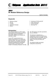
3 Filterbalun Design Principles<br />
The word filterbalun is in this document used to describe all the components necessary to<br />
implement a balun, filter and to ensure proper impedance matching between the radio and<br />
the antenna. A balun is a network that transforms from a balanced to an unbalance signal,<br />
hence the name balun. Figure 1 shows the recommended filterbalun schematic for operation<br />
at <strong>868</strong>/<strong>915</strong> <strong>MHz</strong>. A different topology and different component values are recommended for<br />
operation at 315 and 433 <strong>MHz</strong>. Even if this document describes the <strong>868</strong>/<strong>915</strong> <strong>MHz</strong> filterbalun<br />
in detail, the same principles applies to the 315 and 433 <strong>MHz</strong> filterbalun.<br />
<strong>CC11xx</strong> has differential <strong>RF</strong> ports, <strong>RF</strong>_P and <strong>RF</strong>_N. According to the datasheet the optimum<br />
impedance seen from the chip towards the antenna is Z= 86.5 + j43 Ohm at <strong>868</strong>/<strong>915</strong> <strong>MHz</strong>.<br />
For each port this is equal to Z= 43 + j21.5 Ohm. The impedance at the antenna port is 50<br />
Ohm. To transform the balanced output from the chip to a 50 Ohm unbalanced load, a balun<br />
is used together with matching components<br />
3.1 Schematic and Layout Principles<br />
Digital Inteface<br />
6 GDO0<br />
7 CSn<br />
8 XOSC_Q1<br />
9 AVDD<br />
10 XOSC_Q2<br />
SI 20<br />
GND 19<br />
DGUARD 18<br />
RBIAS 17<br />
GND 16<br />
Figure 1. Schematic of <strong>868</strong>/<strong>915</strong> <strong>MHz</strong> Filterbalun<br />
In TX mode the filterbalun has the following purposes:<br />
• Provide optimum matching for lowest possible current consumption and highest<br />
possible output power.<br />
• Fulfil ETSI (Europe) and FCC (US) regulations in terms of harmonics and spurious<br />
emissions.<br />
In RX mode the filterbalun has the following purpose:<br />
• Provide optimum matching for best possible sensitivity.<br />
Basically the filterbalun can be functionally divided in different parts.<br />
• Differential low pass filter: L121, L131 and C121<br />
• Balun: L122, L132, C131 and C122<br />
• Single ended low pass filter: L123, L124 and C123<br />
• DC-block: C124 and C125<br />
SWRA168 Page 3 of 15
Design Note <strong>DN017</strong><br />
TI provides a separate reference design for all <strong>CC11xx</strong> products. The naming of the<br />
components in the filterbalun differs between the different reference designs, but the<br />
recommended values of the filterbalun components are the same for all the <strong>CC11xx</strong> products.<br />
Note that the recommended values of decoupling capacitors might be different for the<br />
different <strong>CC11xx</strong> products. All component values are provided in the reference designs which<br />
can be downloaded at http://www.ti.com/lpw.<br />
An ideal output signal from the <strong>CC11xx</strong> products in TX mode is a square wave signal at the<br />
<strong>RF</strong>_P and <strong>RF</strong>_N pins and a sine wave at the antenna port. To achieve this, the filterbalun<br />
must reflect the harmonics back towards the <strong>RF</strong>_P and <strong>RF</strong>_N ports. The shape of the square<br />
wave pulse depends on the impedance at the different harmonics. Preferably the odd<br />
harmonics should be reflected back towards the chip with high real part of the impedance.<br />
The current consumption in TX depends on the shape of the signal at <strong>RF</strong>_P and <strong>RF</strong>_N.<br />
Lowest possible current consumption is achieved by having the odd harmonics (3 rd and 5 th )<br />
reflected back as described above. Unexpected high current consumption in a design may be<br />
caused by incorrect or missing reflection of harmonics. The simplest way of reflecting the<br />
harmonics towards the chip is to have a differential low pass filter between the <strong>CC11xx</strong> and<br />
the balun. Ideally the series inductors, L121 and L131, will reflect harmonics towards the<br />
chips with high real part of the impedance. The low pass filter will also lower the harmonics<br />
level into the balun and reducing the risk of having unwanted radiated power through the<br />
balun and the single ended filter.<br />
The balun has a ±90 degrees phase shift implemented by using a low pass filter and a high<br />
pass filter. The important part is to keep the balun as symmetrical as possible. Therefore the<br />
trace length from the single ended port to each of the <strong>RF</strong>–pins should be equal to achieve<br />
best amplitude and phase balance in the balun. An unbalance in the balun causes higher<br />
harmonic level, especially at the 2 nd and 4 th harmonic. Another effect of having an<br />
unsymmetrical balun is reduced output power at the single ended side of the balun. Both<br />
component values and component placement is important to achieve best possible symmetry<br />
in the balun.<br />
The single ended low pass filter presented in figure 1 is dimensioned to fulfil the ETSI<br />
requirement of harmonic emission below -30 dBm. It is recommended to use a T-type filter<br />
instead of a Pi-type filter due to unwanted radiated emission through the shunt capacitors.<br />
The filterbalun is also dimensioned to have 50 Ohm impedance between the balun and the<br />
single ended low pass filter. That means the single ended low pass filter has 50 Ohm<br />
impedance at both sides and can easily be removed or redesigned to fulfil special<br />
requirements. The balun in the 315 and 433 <strong>MHz</strong> reference design are not matched to 50<br />
Ohm, it is only the antenna output which is matched to 50 Ohm in these designs.<br />
Figure 2. 50 Ohm Points in the Filterbalun<br />
SWRA168 Page 4 of 15
Design Note <strong>DN017</strong><br />
A 50 Ohm single ended solution makes it suitable for adding an external PA, LNA or SAW<br />
filter. Switches could be placed in the two 50 Ohm points shown in Figure 2 and a PA<br />
matched to 50 Ohm could be implemented in the TX path after the filter as shown in Figure 3.<br />
Note that the implementation of an external PA most likely requires additional filtering after<br />
the PA to ensure compliance with regulatory requirements.<br />
Figure 3. Implementation of External PA<br />
In designs that only have an antenna without SMA connector and the antenna has no<br />
connection to ground, the DC-block component C125 can be skipped. The essential part is<br />
that the <strong>RF</strong> output from the chip has no DC-connection to ground.<br />
All <strong>CC11xx</strong> chips are characterized on a reference design using multilayer type SMD<br />
inductors. These reference designs can be downloaded from http://www.ti.com/lpw and<br />
contains description of component types and values. Approximately 2 dB higher output power<br />
and reduction of harmonic emission, above 5 GHz, with more than 10 dB can be achieved by<br />
replacing the Multi Layer (ML) type inductors with Wire Wound (WW) inductors. The tradeoff<br />
is that WW inductors are more expensive than ML. See section 5 for more information about<br />
how the inductor type affects the performance.<br />
Component placements should be done according to reference design. Deviation in the<br />
symmetrical filter and balun may cause reduced output power, higher harmonics level, higher<br />
TX current consumption and reduced sensitivity. The layout of the single ended filter towards<br />
the antenna is not that critical as long as the impedance is approximately 50 Ohm. A solid<br />
ground plane should be implemented beneath the <strong>RF</strong> circuitry. It is recommended that the<br />
distance between layer 1, having the <strong>RF</strong> circuitry, and ground is around 0.8-1.0 mm. Shorter<br />
or longer distance may degrade the performance since it will influence the impedance of the<br />
traces in the filterbalun. Changing the thickness of the board will also change the inductance<br />
of the vias. A change of inductance in series with the decoupling capacitors could affect the<br />
performance. The reference design is implemented on a FR4 substrate and it is<br />
recommended to use the same type since the substrate will affect the impedance of the PCB<br />
traces. If a different substrate type or board thickness are used it might be necessary to tune<br />
the value of the filterbalun components to achieve the optimum performance.<br />
Vias should be placed close to all decoupling capacitors to ensure a good connection to the<br />
solid ground plane below. The <strong>CC11xx</strong> reference designs uses 0402 components. Using<br />
0603 component size instead of 0402, the components must be placed as close to each other<br />
as possible and with the same layout as in the <strong>CC11xx</strong> reference designs. The suppression<br />
of harmonics may differ from a 0402 solution due to component parasitics. Components from<br />
different vendors have slightly different performance. Inductors and capacitors from Murata<br />
are used in the <strong>CC11xx</strong> reference design. Thus, using components from different vendors or<br />
different component size than in the reference design might require additional tuning of<br />
component values to achieve optimum performance and sufficient suppression of harmonics.<br />
The optimum impedance for RX and TX is slightly different on the <strong>CC11xx</strong> products. CC1150<br />
is a pure transmitter and has no receiver capabilities. It is therefore possible to achieve<br />
around 1 dB higher output power by tuning the filters, but the current consumption will<br />
SWRA168 Page 5 of 15
Design Note <strong>DN017</strong><br />
increase with approximately 3 mA. Tuning for maximum output power will increase the return<br />
loss at the antenna input and will therefore reduce the sensitivity for the transceivers.<br />
3.2 Simulation Results<br />
The results presented in this chapter are based on simulation of PCB layout and component<br />
models. The PCB layout is electromagnetic (EM) simulated using IE3D from Zeland. The<br />
advantage of using an EM simulator is that PCB effects such as trace length, width, pads,<br />
grounding and coupling will be taking into account. The SMD components are represented by<br />
s-parameters which are provided by the component vendor. The layout model and<br />
components are joint-simulated in a linear s-parameter simulator, Microwave Office (MWO-<br />
100). Since this simulation setup gives a more realistic representation of the filterbalun, the<br />
result will differ from an ideal simulation using only the ideal component values. A zip file with<br />
s-parameters describing the <strong>CC11xx</strong> <strong>868</strong>/<strong>915</strong> <strong>MHz</strong> filterbalun can be downloaded from the<br />
web [3]. A readme file which describes how to interpret the s-parameters is included in this<br />
zip file.<br />
0<br />
<strong>CC11xx</strong> <strong>868</strong><strong>MHz</strong> S11 return loss in RX mode<br />
-5<br />
-10<br />
-15<br />
-20<br />
0.<strong>868</strong> GHz<br />
-17.4 dB<br />
-25<br />
-30<br />
DB(|S(2,2)|)<br />
balun_<strong>868</strong>EM_C_with_SEfilter<br />
DB(|S(2,2)|)<br />
balun_<strong>868</strong>EM_C_without_SEfilter<br />
0.1 0.6 1.1 1.6 2<br />
Frequency (GHz)<br />
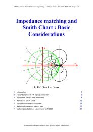
Figure 4. Return Loss at the Antenna Port<br />
Figure 4 shows the Return Loss (RL) at the antenna port. A low RL in the frequency band of<br />
operation is important to achieve good sensitivity. The blue trace<br />
(balun_<strong>868</strong>EM_C_with_SEfilter) is the simulation results of the filterbalun, shown in Figure 1.<br />
The pink trace (balun_<strong>868</strong>EM_C_without_SEfilter) is a similar simulation where the single<br />
ended low pass filter is removed, see Figure 5. Both simulations show low and similar RL for<br />
the <strong>868</strong>/<strong>915</strong> <strong>MHz</strong> frequency band. This indicates that the impedance is very close to 50 Ohm<br />
at both sides of the single-ended filter.<br />
SWRA168 Page 6 of 15
Design Note <strong>DN017</strong><br />
Figure 5. Schematic <strong>868</strong>/<strong>915</strong><strong>MHz</strong> without Single-Ended Filter<br />
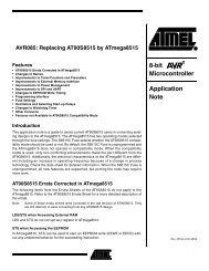
Figure 6 shows the insertion loss for the filterbalun with and without single-ended low pass<br />
filter. The red trace, which is the simulation results of the filterbalun without the single-ended<br />
low pass filter, has 0.35 dB lower loss compared to the filterbalun with the single ended low<br />
pass filter (black trace). This shows that the design is closely matched to 50 Ohm at both<br />
sides of the filter. Figure 6 also show how the filter attenuates signals above 1 GHz.<br />
0<br />
-10<br />
-20<br />
0.<strong>868</strong> GHz<br />
-1.1 dB<br />
<strong>CC11xx</strong> <strong>868</strong><strong>MHz</strong> S21 insertion loss in TX mode<br />
0.<strong>868</strong> GHz<br />
-0.75 dB<br />
DB(|S(2,1)|)<br />
balun_<strong>868</strong>EM_C_without_SEfilter<br />
DB(|S(2,1)|)<br />
balun_<strong>868</strong>EM_C_with_SEfilter<br />
-30<br />
-40<br />
0.1 1.1 2.1 3.1 4.1 5<br />
Frequency (GHz)<br />
Figure 6. Insertion Loss<br />
Figure 7 and Figure 8 shows the amplitude and phase of the differential output signal<br />
respectively. The simulation is performed by applying a signal to the single ended port, port 2,<br />
and plotting the amplitude and phase at the differential ports, port 1 and 3. At <strong>868</strong> <strong>MHz</strong> the<br />
simulated amplitude difference is 1.2 dB and the simulated phase difference is 187.5°.<br />
SWRA168 Page 7 of 15
Design Note <strong>DN017</strong><br />
0<br />
<strong>CC11xx</strong> <strong>868</strong><strong>MHz</strong> Amplitude difference<br />
DB(|S(2,1)|)<br />
balun_<strong>868</strong>EM_C_with_SEfilter_3port<br />
DB(|S(2,3)|)<br />
balun_<strong>868</strong>EM_C_with_SEfilter_3port<br />
-5<br />
0.<strong>868</strong> GHz<br />
-3.5 dB<br />
0.<strong>868</strong> GHz<br />
-4.7 dB<br />
0.<strong>915</strong> GHz<br />
-4.1 dB<br />
0.<strong>915</strong> GHz<br />
-4.6 dB<br />
-10<br />
0 1 2<br />
Frequency (GHz)<br />
Figure 7. Amplitude Difference<br />
200<br />
100<br />
<strong>CC11xx</strong> <strong>868</strong><strong>MHz</strong> Phase difference<br />
0.<strong>868</strong> GHz<br />
120 Deg<br />
0<br />
0.<strong>868</strong> GHz<br />
-67.5 Deg<br />
-100<br />
-200<br />
Ang(S(2,3)) (Deg)<br />
balun_<strong>868</strong>EM_C_with_SEfilter_3port<br />
Ang(S(2,1)) (Deg)<br />
balun_<strong>868</strong>EM_C_with_SEfilter_3port<br />
0.5 1 1.5<br />
Frequency (GHz)<br />
Figure 8. Phase Difference<br />
3.3 <strong>CC11xx</strong> Reference Design History<br />
Three different versions of the reference design have been published, see Figure 9, Figure 10<br />
and Figure 11. The first version had too high harmonic emission, mainly radiating from the<br />
PCB. Therefore the filtering was improved by adding inductors in series with the <strong>RF</strong> pins and<br />
a capacitor in parallel, see Figure 10. When <strong>CC11xx</strong> is programmed for output power levels<br />
between 3 and 7 dBm, the harmonic emission can be higher than when using the 10 dBm<br />
setting. To ensure compliance with ETSI when using the power settings between 3 and 7<br />
dBm, an additional pole was added in the single-ended filter. This is shown in Figure 9. It is<br />
SWRA168 Page 8 of 15
Design Note <strong>DN017</strong><br />
recommended to follow the newest reference design when making new designs because this<br />
gives the best attenuation of harmonic emission and the performance stated in the data<br />
sheet.<br />
Figure 9. Newest Reference Design. Recommended<br />
Figure 10. Second Version of the Reference Design. Not recommended<br />
Figure 11. First Version of the Reference Design. Should not be used<br />
4 Suppressing Spur at 699 <strong>MHz</strong><br />
To be allowed to sell a product intended for operation in the <strong>868</strong> <strong>MHz</strong> frequency band in<br />
Europe, compliance to EN 300 220 must be proven. EN 300 220 requires conducted<br />
measurements of spurious emission if the device uses an antenna connector. For devices<br />
using an integrated antenna, it is sufficient to perform radiated measurements of spurious<br />
emission. Conducted measurements of <strong>CC11xx</strong> show a spurious emission above -54 dBm at<br />
SWRA168 Page 9 of 15
Design Note <strong>DN017</strong><br />
699 <strong>MHz</strong>. This spurious emission shall be measured with the transmitter outputting an<br />
unmodulated carrier and a spectrum analyzer using quasi-peak detector and resolution<br />
bandwidth (RBW) of 100 kHz. At 699 <strong>MHz</strong>, EN 300 220 states that the spurious emission<br />
shall be below -54 dBm. To comply with this requirement a notch filter could be used.<br />
Implementation of such a filter is described in the next section.<br />
4.1 699 <strong>MHz</strong> Notch Filter<br />
The schematic for the notch filter is shown below in Figure 12 and requires only two<br />
additional components compared to the filterbalun in the <strong>CC11xx</strong> reference design. The<br />
recommended component values for the notch filter are listed in Table 1. The rest of the<br />
components should use the values found in the <strong>CC11xx</strong> reference design. For applications<br />
that do not use an antenna connector or doesn’t require compliance with ETSI EN 300 220,<br />
the filter can be left out.<br />
Figure 12. The Notch Filter Schematic<br />
Component Value<br />
C125 12 pF<br />
C126 47 pF<br />
L125 3.3 nH<br />
Table 1. Component Values for the Notch Filter<br />
The layout of the notch filter is not critical. Figure 13 shows an example on how the filter could<br />
be implemented.<br />
Figure 13. Layout of the Notch Filter<br />
SWRA168 Page 10 of 15
Design Note <strong>DN017</strong><br />
4.2 Measurement Results<br />
Measurements with the notch filter have been performed with CC1101 and CC1110. Table 2<br />
shows a comparison of the results from measurements with and without the notch filter. The<br />
measurements were performed on 3 samples at 3.0 V, 25°C and with 10 dBm output power<br />
(PA value 0xC2).<br />
CC1101<br />
CC1110<br />
Without filter With filter Without filter With filter<br />
Spurious emission at 699 <strong>MHz</strong> -52.2 dBm -57.3 dBm -50.6 dBm -57.1 dBm<br />
Output power 10.5 dBm 9.9 dBm 10.6 dBm 9.4 dBm<br />
TX current consumption 32.2 mA 30.2 mA 36.0 mA 33.5 mA<br />
Sensitivity at 250 kbps -93.4 dBm -93.9 dBm -92.4 dBm -92.5 dBm<br />
Table 2. Measurement Results<br />
The ETSI limit for spurious emission at 699 <strong>MHz</strong> is -54 dBm. It can be seen from the<br />
measurements results that the filter can be used to obtain compliance with EN 300 220 for<br />
both the CC1101 and the CC1110. when using an antenna connector.<br />
5 Inductor Types<br />
The type of inductors being used in the filterbalun impacts the performance. There are mainly<br />
two types of inductors to choose from, Wire Wound inductors (WW) and ceramic Multi Layer<br />
(ML) inductors. ML inductors are cheaper than WW inductors. To achieve lowest possible<br />
BOM, ML inductors are being used on all <strong>CC11xx</strong> evaluation boards. WW inductors have less<br />
loss than ML and perform better at high frequencies, but the drawback is increased cost.<br />
The choice of inductor type will affect the performance in terms of output power and<br />
sensitivity, but it will also affect the suppression of harmonic emission. Measurements have<br />
been performed to check how different inductor types affect the performance. The inductor<br />
types used in the testing described in section 5.1 and 5.2 are listed in Table 3. All testes were<br />
performed with conducted measurements on three samples at, 3.0 V, <strong>915</strong> <strong>MHz</strong> and with<br />
power setting 0xC0. Radiated measurements will be affected by the antenna, but will show a<br />
similar trend. Operation at <strong>868</strong> <strong>MHz</strong> will give similar results, but changing the power setting<br />
will affect the output power, current consumption and harmonic emission. See DN012 [4] and<br />
DN013 [5] for more information about output power programming of CC1100, CC1150 and<br />
CC1101.<br />
Inductor Type Manufacturer Series Tolerance<br />
Multi Layer Murata LQG15H ± 5 %<br />
Wire Wound Murata LQW15A ± 2 %<br />
Table 3. Inductors Used for Testing<br />
5.1 Performance<br />
Since WW inductors have less loss than ML type there will be less loss in the filterbalun and<br />
thus higher output power and increased sensitivity. The increased output power will also<br />
result in a slight increase in the current consumption in transmit mode. Table 4 shows that it<br />
is possible to achieve more than 2 dB higher output power and approximately 1 dB improved<br />
sensitivity by using WW inductors.<br />
All inductors ML All inductors WW<br />
TX Current consumption 33.6 mA 35.0 mA<br />
Output power 9.8 dBm 12.0 dBm<br />
Sensitivity 250 kbps -93.7 dBm -94.6 dBm<br />
Table 4. Measured Performance with WW Inductors<br />
SWRA168 Page 11 of 15
Design Note <strong>DN017</strong><br />
5.2 ETSI and FCC Compliance<br />
WW inductors perform better than ML at high frequencies. By using WW instead of ML in the<br />
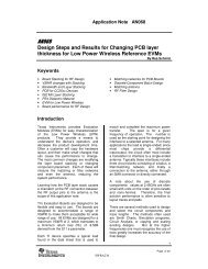
filterbalun is it therefore possible to achieve better suppression of harmonic emission. Figure<br />
14 shows how the PA settings and inductor types affect the level of the harmonic emission.<br />
ETSI<br />
ETSI EN 300 220 requires spurious emission above 1 GHz to be below -30 dBm. When using<br />
ML inductors, the highest PA setting which ensures compliance with ETSI is 0xC2. Using<br />
0xC0 which is the <strong>CC11xx</strong> PA setting resulting in maximum output power will result in a level<br />
of 2nd harmonic which is at the ETSI limit. It is therefore recommended to use WW inductors<br />
in the filterbalun to achieve highest possible output power when seeking compliance with<br />
ETSI EN 300 220.<br />
FCC<br />
FCC part 15.247 allows for up to 1 W output power if Frequency Hopping (FH) or digital<br />
modulation is used. Maximum output power for <strong>CC11xx</strong> is 10 dBm. DN006 [6] describes how<br />
<strong>CC11xx</strong> can be configured to comply with FCC 15.247 without using FH. Part 15.247 requires<br />
the spurious emission to be 20 dB below the intentional radiator except inside restricted<br />
bands which are defined in part 15.205. The 2 nd and 7 th harmonic is the only harmonics below<br />
10 GHz which doesn’t fall within any restricted bands when operating in the 902-928 <strong>MHz</strong><br />
ISM band. The spurious emission limit is -41.2 dBm inside the restricted bands, but FCC<br />
allows for up to 20 dB higher emission if duty cycling is being used. The maximum TX on time<br />
must be less than 100 ms to get a benefit from this rule. By using Equation 1 and the<br />
maximum on time of the application, it is possible to calculate the Averaging Factor (AF). The<br />
spurious level accepted by FCC would then be -41.2 dBm + AF, and maximum -21.2 dBm<br />
⎛ MAX TX ON TIME ms ⎞<br />
AF = −20<br />
LOG⎜<br />
⎟<br />
⎝ 100ms<br />
⎠<br />
Equation 1. Averaging Factor<br />
FCC spurious emission limits are plotter in Figure 14 together with harmonic measurements.<br />
Both the limit for maximum AF and no AF are plotted. At the 2 nd and 7 th harmonic the limit is<br />
plotted at -10 dBm since CC11x has maximum output power of 10 dBm and the requirement<br />
is 20 dB below maximum radiation.<br />
SWRA168 Page 12 of 15
Design Note <strong>DN017</strong><br />
0<br />
Harmonic Emission<br />
Level [dBm]<br />
-10<br />
-20<br />
-30<br />
-40<br />
-50<br />
All inductor ML<br />
PA = 0xC0<br />
All inductor ML<br />
PA = 0xC2<br />
L124 WW rest<br />
ML PA = 0xC0<br />
All inductors WW<br />
PA = 0xC0<br />
FCC 15.247 TX<br />
on time > 100 ms<br />
FCC 15.247 Duty<br />
Cycling<br />
ETSI EN 300 220<br />
-60<br />
2 3 4 5 6 7 8 9 10<br />
Harmonic<br />
Figure 14. Measured Harmonic Emission<br />
Table 5 shows which combinations of output power settings and inductors types that can be<br />
used to comply with FCC part 15.247 and ETSI EN 300 220.<br />
Graph<br />
Inductor types All inductor<br />
ML<br />
All inductor<br />
ML<br />
L124 WW<br />
rest ML<br />
All inductors<br />
WW<br />
PA setting PA = 0xC2 PA = 0xC0 PA = 0xC0 PA = 0xC0<br />
TX Current<br />
30.4 mA 33.6 mA 32.9 mA 35.0 mA<br />
consumption<br />
Output power 9.3 dBm 9.8 dBm 9.8 dBm 12.0 dBm<br />
2 nd Harmonic -37.3 dBm -30.8 dBm -29.3 dBm -34.8 dBm<br />
Sensitivity -93.7 dBm -93.7 dBm -94.0 dBm -94.6 dBm<br />
Complies with FCC Requires duty Requires duty<br />
Yes<br />
Yes<br />
cycle<br />
cycle<br />
Complies with ETSI Yes No margin No Yes<br />
Table 5. Measure Performance with All ML and One WW Inductor<br />
SWRA168 Page 13 of 15
Design Note <strong>DN017</strong><br />
6 References<br />
[1] CC1101EM <strong>868</strong>-<strong>915</strong><strong>MHz</strong> Reference Design (swrr045.zip)<br />
[2] CC1110EM <strong>868</strong>-<strong>915</strong><strong>MHz</strong> Reference Design (swrr048.zip)<br />
[3] <strong>CC11xx</strong> <strong>868</strong>/<strong>915</strong><strong>MHz</strong> <strong>RF</strong> matching S-parameters (swrc091.zip)<br />
[4] DN012 Programming Output Power on CC1100 and CC1150 (swra150.pdf)<br />
[5] DN013 Programming Output Power on CC1101 (swra151.pdf)<br />
[6] DN006 <strong>CC11xx</strong> Settings for FCC 15.247 Solutions (swra123.pdf)<br />
SWRA168 Page 14 of 15
Design Note <strong>DN017</strong><br />
7 Document History<br />
Revision Date Description/Changes<br />
SWRA168 2008.02.01 Initial release.<br />
SWRA168 Page 15 of 15
IMPORTANT NOTICE<br />
Texas Instruments Incorporated and its subsidiaries (TI) reserve the right to make corrections, modifications, enhancements, improvements,<br />
and other changes to its products and services at any time and to discontinue any product or service without notice. Customers should<br />
obtain the latest relevant information before placing orders and should verify that such information is current and complete. All products are<br />
sold subject to TI’s terms and conditions of sale supplied at the time of order acknowledgment.<br />
TI warrants performance of its hardware products to the specifications applicable at the time of sale in accordance with TI’s standard<br />
warranty. Testing and other quality control techniques are used to the extent TI deems necessary to support this warranty. Except where<br />
mandated by government requirements, testing of all parameters of each product is not necessarily performed.<br />
TI assumes no liability for applications assistance or customer product design. Customers are responsible for their products and<br />
applications using TI components. To minimize the risks associated with customer products and applications, customers should provide<br />
adequate design and operating safeguards.<br />
TI does not warrant or represent that any license, either express or implied, is granted under any TI patent right, copyright, mask work right,<br />
or other TI intellectual property right relating to any combination, machine, or process in which TI products or services are used. Information<br />
published by TI regarding third-party products or services does not constitute a license from TI to use such products or services or a<br />
warranty or endorsement thereof. Use of such information may require a license from a third party under the patents or other intellectual<br />
property of the third party, or a license from TI under the patents or other intellectual property of TI.<br />
Reproduction of TI information in TI data books or data sheets is permissible only if reproduction is without alteration and is accompanied<br />
by all associated warranties, conditions, limitations, and notices. Reproduction of this information with alteration is an unfair and deceptive<br />
business practice. TI is not responsible or liable for such altered documentation. Information of third parties may be subject to additional<br />
restrictions.<br />
Resale of TI products or services with statements different from or beyond the parameters stated by TI for that product or service voids all<br />
express and any implied warranties for the associated TI product or service and is an unfair and deceptive business practice. TI is not<br />
responsible or liable for any such statements.<br />
TI products are not authorized for use in safety-critical applications (such as life support) where a failure of the TI product would reasonably<br />
be expected to cause severe personal injury or death, unless officers of the parties have executed an agreement specifically governing<br />
such use. Buyers represent that they have all necessary expertise in the safety and regulatory ramifications of their applications, and<br />
acknowledge and agree that they are solely responsible for all legal, regulatory and safety-related requirements concerning their products<br />
and any use of TI products in such safety-critical applications, notwithstanding any applications-related information or support that may be<br />
provided by TI. Further, Buyers must fully indemnify TI and its representatives against any damages arising out of the use of TI products in<br />
such safety-critical applications.<br />
TI products are neither designed nor intended for use in military/aerospace applications or environments unless the TI products are<br />
specifically designated by TI as military-grade or "enhanced plastic." Only products designated by TI as military-grade meet military<br />
specifications. Buyers acknowledge and agree that any such use of TI products which TI has not designated as military-grade is solely at<br />
the Buyer's risk, and that they are solely responsible for compliance with all legal and regulatory requirements in connection with such use.<br />
TI products are neither designed nor intended for use in automotive applications or environments unless the specific TI products are<br />
designated by TI as compliant with ISO/TS 16949 requirements. Buyers acknowledge and agree that, if they use any non-designated<br />
products in automotive applications, TI will not be responsible for any failure to meet such requirements.<br />
Following are URLs where you can obtain information on other Texas Instruments products and application solutions:<br />
Products<br />
Applications<br />
Amplifiers amplifier.ti.com Audio www.ti.com/audio<br />
Data Converters dataconverter.ti.com Automotive www.ti.com/automotive<br />
DSP dsp.ti.com Broadband www.ti.com/broadband<br />
Clocks and Timers www.ti.com/clocks Digital Control www.ti.com/digitalcontrol<br />
Interface interface.ti.com Medical www.ti.com/medical<br />
Logic logic.ti.com Military www.ti.com/military<br />
Power Mgmt power.ti.com Optical Networking www.ti.com/opticalnetwork<br />
Microcontrollers microcontroller.ti.com Security www.ti.com/security<br />
<strong>RF</strong>ID www.ti-rfid.com Telephony www.ti.com/telephony<br />
<strong>RF</strong>/IF and ZigBee® Solutions www.ti.com/lprf Video & Imaging www.ti.com/video<br />
Wireless<br />
www.ti.com/wireless<br />
Mailing Address: Texas Instruments, Post Office Box 655303, Dallas, Texas 75265<br />
Copyright © 2008, Texas Instruments Incorporated