LectroCount3 Calibration Procedures Addendum - Liquid Controls
LectroCount3 Calibration Procedures Addendum - Liquid Controls
LectroCount3 Calibration Procedures Addendum - Liquid Controls

Create successful ePaper yourself
Turn your PDF publications into a flip-book with our unique Google optimized e-Paper software.
CALIBRATION MODE (PROVER MODE)<br />
CAUTION<br />
All of the calibration mode screens must be properly setup in order for the meter to operate<br />
properly. Incorrect settings can result in inaccurate measurements, lost product, unexpected<br />
operation and damage to equipment or property. Setup and calibration should be performed<br />
ONLY by trained and authorized personnel. If you have any questions contact your Authorized<br />
<strong>Liquid</strong> <strong>Controls</strong> Distributor or <strong>Liquid</strong> <strong>Controls</strong> Customer Service at 1-800-458-5262.<br />
CALIBRATION PROCEDURE<br />
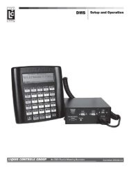
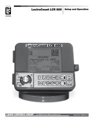
PROVER MODE is used for meter calibration. When proving the LectroCount 3 System, follow pre-test and<br />
inspection procedures established by Weights and Measures authorities. The primary indicating and recording<br />
element on a vehicle mounted LectroCount 3 is located on the Lap Pad in the truck cab. A remote 6-digit (meter<br />
mounted) liquid crystal display is provided for operator convenience and consumer verification.<br />
Weights and Measures inspectors are responsible for determining if the truck metering and recording elements of the<br />
system are in tolerance. To make this determination, the system should be tested under normal operating<br />
conditions.<br />
After the initial calibration, access to the calibration mode is required only if the system is in excess of established<br />
tolerances or the W & M inspector elects to run special tests (i.e., establishing the accuracy of both the measuring<br />
element and the compensating elements of the system).<br />
Refer to Page 5 of the Owner’s Manual 49145E for information on how to operate the Lap Pad. In general, data input<br />
is performed by pressing the numerical keys on the key pad, followed by pressing the ENTER key.<br />
1. First select the product to be proved. If the unit is equipped with 8 Product Software, enter Mode 1 by pushing<br />
M1 on the Lap Pad. Scroll down to PRODUCT CODE and enter the code for the product being calibrated.<br />
Each product needs to be calibrated separately in the prover mode. See Mode 17 on Page 11 of the owners<br />
manual for product set-up.<br />
If the unit is equipped with 24 product software, enter Mode 21 by pushing M# , 2 1. Enter and select one of the<br />
four possible calibrations. Each calibration needs to be done separately in the prover mode.<br />
2. Remove the lead seal and wire assembly from the Remote Supervisory Control Box.<br />
3. Remove the four (4) fillister head screws securing the name plate of the red selector switch located on the<br />
Remote Supervisory Control Box.<br />
4. Enter the calibration mode by turning the red switch to the PROVER position, full counterclockwise (6:00 o’clock<br />
position). The prover mode is used to change the calibration of the meter, electronic temperature compensator<br />
or both. When the switch is in the prover position, the prompting display will read: [INSERT TICKET AND PUSH<br />
ENTER OR PUSH STOP]. Insert a ticket and push ENTER to print the initial prover ticket. The prompting<br />
display will again read: [INSERT TICKET AND PUSH ENTER OR PUSH STOP]. Insert a second ticket and<br />
prepare to prove the system.<br />
NOTE: When proving a truck meter, the truck compartment should be at least 70% full to avoid metering hot,<br />
foamy product and to ensure accurate proving.<br />
5. If this is a new installation, a value for PULSES/UNIT VOLUME must be entered. Scroll through the prover mode<br />
screens using the ↓ key until you reach the PULSES/UNIT VOLUME screen. Refer to Table B and choose a<br />
value based on the type, make and model of the meter. Type in the value and press the ENTER key.<br />
6. If proving a temperature compensated meter and register, the meter should first be tested for accuracy without<br />
using the temperature compensation feature. Scroll through the prover mode screens to the TEMP COEF or<br />
DENSITY or ENABLE VCF TABLE screen. Write down the value that appears here and then enter 0.00 to<br />
defeat temperature compensation.<br />
2