LectroCount3 Calibration Procedures Addendum - Liquid Controls
LectroCount3 Calibration Procedures Addendum - Liquid Controls
LectroCount3 Calibration Procedures Addendum - Liquid Controls

Create successful ePaper yourself
Turn your PDF publications into a flip-book with our unique Google optimized e-Paper software.
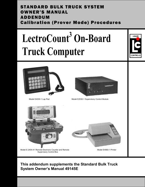
STANDARD BULK TRUCK SYSTEM<br />
OWNER’S MANUAL<br />
ADDENDUM<br />
<strong>Calibration</strong> (Prover Mode) <strong>Procedures</strong><br />
LectroCount 3 On-Board<br />
Truck Computer<br />
Model E4030-1 Lap Pad<br />
Model E2530-1 Supervisory Control Module<br />
Model E-2404-41 Remote Electronic Counter and Remote<br />
Supervisory Control Box<br />
Model E4900-1 Printer<br />
This addendum supplements the Standard Bulk Truck<br />
System Owner’s Manual 49145E
CALIBRATION MODE (PROVER MODE)<br />
CAUTION<br />
All of the calibration mode screens must be properly setup in order for the meter to operate<br />
properly. Incorrect settings can result in inaccurate measurements, lost product, unexpected<br />
operation and damage to equipment or property. Setup and calibration should be performed<br />
ONLY by trained and authorized personnel. If you have any questions contact your Authorized<br />
<strong>Liquid</strong> <strong>Controls</strong> Distributor or <strong>Liquid</strong> <strong>Controls</strong> Customer Service at 1-800-458-5262.<br />
CALIBRATION PROCEDURE<br />
PROVER MODE is used for meter calibration. When proving the LectroCount 3 System, follow pre-test and<br />
inspection procedures established by Weights and Measures authorities. The primary indicating and recording<br />
element on a vehicle mounted LectroCount 3 is located on the Lap Pad in the truck cab. A remote 6-digit (meter<br />
mounted) liquid crystal display is provided for operator convenience and consumer verification.<br />
Weights and Measures inspectors are responsible for determining if the truck metering and recording elements of the<br />
system are in tolerance. To make this determination, the system should be tested under normal operating<br />
conditions.<br />
After the initial calibration, access to the calibration mode is required only if the system is in excess of established<br />
tolerances or the W & M inspector elects to run special tests (i.e., establishing the accuracy of both the measuring<br />
element and the compensating elements of the system).<br />
Refer to Page 5 of the Owner’s Manual 49145E for information on how to operate the Lap Pad. In general, data input<br />
is performed by pressing the numerical keys on the key pad, followed by pressing the ENTER key.<br />
1. First select the product to be proved. If the unit is equipped with 8 Product Software, enter Mode 1 by pushing<br />
M1 on the Lap Pad. Scroll down to PRODUCT CODE and enter the code for the product being calibrated.<br />
Each product needs to be calibrated separately in the prover mode. See Mode 17 on Page 11 of the owners<br />
manual for product set-up.<br />
If the unit is equipped with 24 product software, enter Mode 21 by pushing M# , 2 1. Enter and select one of the<br />
four possible calibrations. Each calibration needs to be done separately in the prover mode.<br />
2. Remove the lead seal and wire assembly from the Remote Supervisory Control Box.<br />
3. Remove the four (4) fillister head screws securing the name plate of the red selector switch located on the<br />
Remote Supervisory Control Box.<br />
4. Enter the calibration mode by turning the red switch to the PROVER position, full counterclockwise (6:00 o’clock<br />
position). The prover mode is used to change the calibration of the meter, electronic temperature compensator<br />
or both. When the switch is in the prover position, the prompting display will read: [INSERT TICKET AND PUSH<br />
ENTER OR PUSH STOP]. Insert a ticket and push ENTER to print the initial prover ticket. The prompting<br />
display will again read: [INSERT TICKET AND PUSH ENTER OR PUSH STOP]. Insert a second ticket and<br />
prepare to prove the system.<br />
NOTE: When proving a truck meter, the truck compartment should be at least 70% full to avoid metering hot,<br />
foamy product and to ensure accurate proving.<br />
5. If this is a new installation, a value for PULSES/UNIT VOLUME must be entered. Scroll through the prover mode<br />
screens using the ↓ key until you reach the PULSES/UNIT VOLUME screen. Refer to Table B and choose a<br />
value based on the type, make and model of the meter. Type in the value and press the ENTER key.<br />
6. If proving a temperature compensated meter and register, the meter should first be tested for accuracy without<br />
using the temperature compensation feature. Scroll through the prover mode screens to the TEMP COEF or<br />
DENSITY or ENABLE VCF TABLE screen. Write down the value that appears here and then enter 0.00 to<br />
defeat temperature compensation.<br />
2
7. Push START and deliver a known volume to a reliable, accurate prover, weight scale or master meter.<br />
8. Push STOP . The prompting display will indicate GROSS VOLUME that the meter measured.<br />
9. Scroll through the prover mode screens using the ↓ key until you reach the GROSS VOLUME<br />
GALLONS (or LITRES) screen. ENTER THE VOLUME READING SHOWN ON THE PROVER*. Never<br />
enter zero. The register will automatically adjust the pulses/unit to correct for any inaccuracy.<br />
10. Scroll through the prover mode screens using the ↓ key until you reach the Pulses/Litre<br />
(Pulses/Gallon) value. Write it down on a piece of paper.<br />
11. Repeat steps 7 through 10 two more times in order to stabilize the system temperature and wet the<br />
prover walls.<br />
12. Using a calculator, divide the last Pulses/Litre (Pulses/Gallon) value by the value on the previous cycle. If<br />
the answer is NOT between 0.9975 and 1.0025, repeat steps 7 through 10 until it is.<br />
Example: This Prover Run = 2231 pulses/gallon<br />
Previous Prover Run = 2229 pulses/gallon<br />
2231/2229 = 1.000897 (Which is in the acceptable range)<br />
With the meter itself proved, the next step is to adjust the temperature compensation if necessary.<br />
Net volume is calculated from gross volume by considering the effects of temperature variations on<br />
the product.<br />
13. Enable the temperature compensation once more. Scroll through the prover mode screens to the TEMP<br />
COEF or DENSITY or ENABLE VCF TABLE screen. If your system has an ENABLE VCF TABLE screen,<br />
enter 1 to enable temperature compensation. If your system has a TEMP COEF or DENSITY screen,<br />
enter the temperature coefficient for the fluid or the standard density recorded in Step 6, or refer to<br />
TABLE A for assistance in selecting the correct value. If the unit has DENSITY software the<br />
LectroCount 3 will calculate a correction table. During the calculations the unit may be disabled for about<br />
5 minutes.<br />
14. If the unit has TEMP COEF or DENSITY software, scroll through the prover mode screens to the BASE<br />
TEMP screen and enter the proper value (usually 60°F or 15°C). Refer to Table A for the correct base<br />
temperature.<br />
15. Deliver enough product to the prover to stabilize the liquid system temperature.<br />
16. Push START and deliver a known volume to a reliable, accurate prover, weight scale or master meter.<br />
17. Push STOP .<br />
18. Scroll down through the prover mode screens to the TEMP THIS DEL F (C) screen, and compare the<br />
value shown with the Weights and Measures thermometer reading. If there is a discrepancy scroll down<br />
to the CALIBRATED PROBE TEMPERATURE screen. Enter the Weights and Measures thermometer<br />
reading. The register will automatically calculate a new TEMP OFFSET – DEG F (C), resulting in a<br />
change in the net volume delivered on the NEXT prover run.<br />
19. Repeat Steps 1 through 18 for all remaining Product Codes or all remaining Product <strong>Calibration</strong>s (as<br />
described in Step 1) used on this register.<br />
20. <strong>Calibration</strong> is not complete until all of the settings and measurements have been properly made, the red<br />
switch is returned to the STOP position, the switch plate and screws are replaced and a seal wire is<br />
affixed. A final prover ticket will automatically be printed upon exiting prover mode. NOTE: For the<br />
calibration changes to be saved a final prover ticket must be printed. CAUTION: If power is lost for any<br />
reason while in prover mode, all calibration changes will be lost.<br />
* The prover reading is gross value, but many jurisdictions also require you to include the prover’s<br />
correction factor. This correction factor takes into account the change in prover volume with product<br />
temperature. When proving at temperatures less than 15°C, the prover tank shrinks and the correction<br />
factor is a negative value (Example: -.25 litres). When proving at temperatures above 15°C, the prover<br />
tank expands and the correction factor is a positive value (Example: +.30 litres). The prover readings for<br />
Gross Volume plus the correction factor is entered into the Lap Pad’s display of Gross Volume Litres<br />
(Gallons). The computer automatically recalculates Pulse/Litre.<br />
3
CALIBRATION MODE (PROVER MODE)<br />
Compensation Types and Parameters<br />
Product VCF Type Scale Parameter Range Tbase Tmin Tmax<br />
General (USA) Linear °F Linear 0.01 to 0 **<br />
60 -40 +95<br />
Aviation Fuel – 0.00052<br />
Diesel Fuel, #2 and Home<br />
Heating Oil – 0.0005<br />
Gasoline - 0.0007<br />
LPG – 0.0016<br />
Lube Oils – 0.0004<br />
Methanol - .00066<br />
NH3 – 0.0013<br />
General Linear °C Linear 0.01 to 0 15 -40 +95<br />
LPG (Canada) API Table 54 °C Density Fixed 0.510 15 -46 +60<br />
Kg/l<br />
Refined Petroleum<br />
Products (Canada)<br />
API Table 54B °C Density<br />
Kg/m 3 653 to 1075 ***<br />
Gasoline – 730<br />
Aviation Fuel – 800<br />
Diesel Fuel – 840<br />
15 -40 +95<br />
Ammonia (NH3) NH3 °C N/A N/A 15 -30 +40<br />
(Canada)<br />
Methanol API Table 54C °C N/A N/A 15 -30 +40<br />
Table A<br />
** The actual linear correction value for your measured fluid should be used. This value can usually be obtained through<br />
your supplier.<br />
*** The actual density value for your measured fluid should be used. This value can usually be obtained through your<br />
supplier.<br />
Initial <strong>Calibration</strong> Factors (K-Factors) for selected meters<br />
For internal encoders with 1:1 packing glands or POD pulsers<br />
Note: Values are approximate. <strong>Calibration</strong> is ALWAYS required.<br />
Manufacturer Model Number Pulses / Gallon Pulses / Litre<br />
<strong>Liquid</strong> <strong>Controls</strong> M-4, M-5, MA5 1632 431<br />
M-7, MA-7, MS-7, M-10 2222 587<br />
M-15, MA-15, MS-15, M-25, MS-25 823 217<br />
M-30, MS-30, M40, MS-40 297 78<br />
Neptune 1 ½” and 2” 370 98<br />
Brooks All truck mounted meters 400 106<br />
A.O. Smith T-11 1200 317<br />
T-20 675 178<br />
Table B<br />
HOW TEMPERATURE COMPENSATION CALCULATIONS ARE MADE<br />
EXAMPLE: Using a 1,000 gallon gross quantity:<br />
Base temperature = 60° F<br />
Temperature coefficient = 0.00045000000<br />
Temperature this delivery = 65°F<br />
Gross volume gallons = 1,000 gallons<br />
The volume correction factor (VCF) is calculated by<br />
taking the temperature deviation multiplied by the<br />
temperature coefficient and subtracting from 1.<br />
VCF = 1 – (Temp Dev x Temp Coef)<br />
VCF = 1 – (5 x 0.00045) = 0.99775<br />
Temperature deviation is calculated by subtracting the base<br />
temperature from the temperature this delivery.<br />
Temp Dev = Temp This Del – Base Temp<br />
Since the product temperature is higher than the base<br />
temperature, the amount of product delivered is slightly less<br />
than it would be at the base temperature. The net volume is<br />
the gross volume times the volume correction factor.<br />
Net volume = gross volume x volume correction factor (VCF)<br />
Net volume = 1,000 x 0.99775 = 997.75<br />
4
CALIBRATION MODE (PROVER MODE) SCREENS<br />
Due to the numerous variations in operating software for the <strong>LectroCount3</strong>, each of the screens that follows may<br />
or may not apply to your particular software. The screen text from the lap pad is shown in a box, followed by an<br />
explanation of the screen function and settings. Numerical information that may appear in the screen box is an<br />
EXAMPLE ONLY and DOES NOT apply to any particular system.<br />
GROSS VOLUME GALLONS (or Litres) 0.0<br />
CALIBRATION MODE<br />
This is the primary proving display, which shows the amount of Gross (uncompensated) fluid delivered. This may<br />
be in Gallons or in Litres depending upon the particular software used in the system. The actual delivered volume<br />
as measured by the prover should be entered here as instructed in the <strong>Calibration</strong> Procedure on Page 2 and 3.<br />
NET VOLUME GALLONS (or Litres) 0.0<br />
CALIBRATION MODE<br />
(Temperature compensated systems only). This display shows the amount of Net (compensated) fluid delivered.<br />
The compensation amount is based upon the Gross volume as well as the compensation type and compensation<br />
parameters described below. This may be in Gallons or in Litres depending upon the particular software used in<br />
the system.<br />
PRODUCT CODE 1<br />
CALIBRATION MODE<br />
(8 Product Systems Only). This value indicates the product code that is currently being proved. This is for display<br />
only and cannot be changed within <strong>Calibration</strong> Mode. It must be selected before entering <strong>Calibration</strong> Mode (see<br />
instructions above).<br />
CALIBRATION NUMBER 1<br />
CALIBRATION MODE<br />
(24 Product Systems Only). On systems with 24 product software, each product must use one of four possible<br />
calibration numbers (or factors). This value (1 through 4) indicates which calibration number is currently being<br />
proved.<br />
PRODUCT CLASS<br />
GASOLINE<br />
ENTER 1 TO CHANGE PRODUCT CLASS<br />
(24 Product Systems Only). On systems with 24 product software, the product class is a label that is permanently<br />
tied to this calibration number and will print on all subsequent delivery tickets. You may select from the following:<br />
GASOLINE, DISTILLATE, AVIATION, METHANOL, AMMONIA, LPG. The UNIDENTIFIED label can be typed<br />
over to create product classes other than those listed.<br />
TEMP COEFFICIENT *F (or *C) .0000000000<br />
CALIBRATION MODE<br />
(Temperature Compensated systems only. Typically US and Mexico.) On temperature compensated systems with<br />
linear type compensation, a temperature coefficient is required to properly correct the volume. The temperature<br />
coefficient may be either for Degrees F or for degrees C depending on the specific software used. Refer to Table<br />
A to assist you in selecting the correct temperature coefficient for the fluid being measured. NOTE: ENTERING A<br />
VALUE OF “0” WILL DEFEAT THE TEMPERATURE COMPENSATION. ENTERING THE INCORRECT VALUE<br />
CAN RESULT IN INACCURATE MEASUREMENTS AND UNEXPECTED OPERATION. IF YOU HAVE ANY<br />
QUESTIONS, OR ARE UNSURE OF THE PROPER VALUE TO USE, CONTACT AN AUTHORIZED LIQUID<br />
CONTROLS REPRESENTATIVE FOR ASSISTANCE.<br />
DENSITY AT 15 C 0.00<br />
CALIBRATION MODE<br />
(Temperature Compensated systems only. Typically Canadian Refined Fuels.) On temperature compensated<br />
systems with density based compensation (table 54B), a product density value at standard temperature (15<br />
degrees C) is required to properly correct the volume. The density value must be entered in units of kg/m 3 . Refer<br />
to Table A to assist you in selecting the correct density value for the fluid being measured.<br />
If the density initially entered is 730 GASOLINE, 800 AVIATION or 840 DIESEL it will take about 10 seconds to<br />
calculate the table. All other densities will initially take about 4 minutes and will display --- VCF CALCULATION<br />
ACTIVE --- until the table is calculated. On 8 product software, the density entered will determine the product<br />
class that is printed on the delivery tickets (ie. GASOLINE, AVIATION, DISTILLATE …).<br />
NOTE: ENTERING A VALUE OF “0” WILL DEFEAT THE TEMPERATURE COMPENSATION. ENTERING THE<br />
INCORRECT VALUE CAN RESULT IN INACCURATE MEASUREMENTS AND UNEXPECTED OPERATION. IF<br />
YOU HAVE ANY QUESTIONS, OR ARE UNSURE OF THE PROPER VALUE TO USE, CONTACT AN<br />
AUTHORIZED LIQUID CONTROLS REPRESENTATIVE FOR ASSISTANCE.<br />
5
CALIBRATION MODE (PROVER MODE)<br />
CALIBRATION MODE (PROVER MODE) SCREENS (CONTINUED)<br />
ENABLE LPG VCF TABLE 1<br />
CALIBRATION MODE<br />
(Temperature Compensated systems only. Typically Canadian LPG.) On Canadian LPG systems with Table 54<br />
based compensation, a hard coded product density value of 0.510 kg/l is used to properly correct the volume.<br />
Entering a value of “1” will enable temperature compensation. NOTE: ENTERING A VALUE OF “0” WILL<br />
DEFEAT THE TEMPERATURE COMPENSATION.<br />
ENABLE NH3 VCF TABLE 1<br />
CALIBRATION MODE<br />
(Temperature Compensated systems only. Typically Canadian NH3.) On Canadian NH3 systems with<br />
temperature compensation, a hard coded compensation table is used to properly correct the volume. Entering a<br />
value of “1” will enable temperature compensation. NOTE: ENTERING A VALUE OF “0” WILL DEFEAT THE<br />
TEMPERATURE COMPENSATION.<br />
MEAN VCF 0.0000000000<br />
CALIBRATION MODE<br />
(Temperature Compensated systems only). The mean Volume Correction Factor (VCF) is displayed for<br />
reference. The Net volume is calculated by multiplying the Gross volume by the VCF. The VCF is calculated by<br />
the <strong>LectroCount3</strong> based upon the type of compensation used in the version of software installed.<br />
BASE TEMPERATURE *F (or *C) 60<br />
CALIBRATION MODE<br />
(Temperature Compensated systems only). The base temperature is both entered and displayed here, and is<br />
typically 60 degrees Fahrenheit for US systems and 15 degrees Celsius for Canadian and other systems. Refer to<br />
Table A for the correct value to use. The difference between the Base temperature and the actual Product<br />
temperature is used, in part, to calculate the VCF. NOTE: ENTERING THE INCORRECT VALUE CAN RESULT<br />
IN INACCURATE MEASUREMENTS AND UNEXPECTED OPERATION.<br />
TEMP. THIS DELIVERY *C (or *F) 10.9<br />
CALIBRATION MODE<br />
(Temperature Compensated systems only. Some versions of software do not display this value.) The actual<br />
product temperature for this delivery is displayed for reference only and is in degrees Fahrenheit for US systems<br />
and in degrees Celsius for Canadian and other systems. The difference between the Base temperature and the<br />
actual Product temperature is used, in part, to calculate the VCF.<br />
UNCALIBRATED PROBE TEMPERATURE *C 10.90<br />
CALIBRATION MODE<br />
(Temperature Compensated systems only). The actual, uncalibrated (or raw) probe temperature is displayed for<br />
reference only and is in degrees Fahrenheit for US systems and in degrees Celsius for Canadian and other<br />
systems. The calibrated temperature is the uncalibrated temperature minus the temperature offset.<br />
CALIBRATED PROBE TEMPERATURE *C(F) 10.89<br />
CALIBRATION MODE<br />
(Temperature Compensated systems only). The calibrated (or adjusted) probe temperature is both entered and<br />
displayed here. The calibrated temperature is in degrees Fahrenheit for US systems and in degrees Celsius for<br />
Canadian and other systems. During a proving run, the temperature as measured by the Weights and Measures<br />
thermometer is entered here. The register then calculates a new Temp. Offset-Deg (see below). The calibrated<br />
temperature is the uncalibrated temperature minus the temperature offset.<br />
TEMP. OFFSET-DEG *C(F) 0.01<br />
CALIBRATION MODE<br />
(Temperature Compensated systems only). The temperature offset is both entered and displayed here and is in<br />
degrees Fahrenheit for US systems and in degrees Celsius for Canadian and other systems. The temperature<br />
offset is the measured difference between the Uncalibrated probe temperature and the actual temperature as<br />
measured by the Weights and Measures inspector. While the temperature offset can be entered directly into this<br />
screen, it is recommended that the actual temperature be entered into the Calibrated Probe Temperature Screen<br />
instead.<br />
6
UNIT ID NUMBER 1.<br />
CALIBRATION MODE<br />
The Unit ID Number is a number generated by the owner to uniquely identify this register from others. Since the<br />
register is calibrated to a specific meter, the register serial number is typically entered here. The Unit ID number can<br />
be viewed or changed from this screen. This number will be printed on calibration and diagnostic tickets for<br />
reference.<br />
METER NUMBER 1.<br />
CALIBRATION MODE<br />
The Meter Number is a number generated by the owner to uniquely identify the meter used with this register from<br />
others. Since the register is calibrated to a specific meter, the meter serial number is typically entered here. The<br />
meter number can be viewed or changed from this screen. This number will be printed on calibration and diagnostic<br />
tickets for reference.<br />
TRUCK NUMBER 1.<br />
CALIBRATION MODE<br />
The Truck Number is a number generated by the owner to uniquely identify this truck (if used) from others. The Truck<br />
Number can be viewed or changed from this screen. This number will be printed on calibration and diagnostic tickets<br />
for reference.<br />
MAX FLOW RATE EVER 87.3<br />
CALIBRATION MODE<br />
(Not on all versions of software). Reference only. This screen shows the maximum flow rate ever measured on this<br />
register. The units are the primary units of measure for this register (typically Gallons or Litres) PER MINUTE. This<br />
value can be reset by entering a “0” on this screen.<br />
MAX FLOW RATE LAST DELIVERY 46.5<br />
CALIBRATION MODE<br />
(Not on all versions of software). Reference only. This screen shows the maximum flow rate measured on the last<br />
delivery. The units are the primary units of measure for this register (typically Gallons or Litres) PER MINUTE. This<br />
value is reset on each delivery.<br />
The following screens are related to valve setup. For definitions, refer to MODE 4 information on pages 6 and<br />
7 of the Owner’s Manual 49145E.<br />
MAX PRESET VOLUME<br />
FIRST STAGE CLOSURE<br />
THROTTLE CONTROL VOLUME<br />
MAX PULSER REVERSALS<br />
ACTUAL PULSER REVERSALS<br />
NO FLOW TIMEOUT (.1 SEC)<br />
VALVE CLOSE TIME (.1 SEC)<br />
VALVE TYPE, DIDDLE=1, 1 OR 2 STAGE=0<br />
HIGH FLOW (UNITS/MIN)<br />
LOW FLOW (UNITS/MIN)<br />
VALVE OPENING DELAY<br />
VALVE CLOSING DELAY<br />
SOLENOID OPEN TIME<br />
SOLENOID CLOSE TIME<br />
DEAD BAND<br />
BYPASS PULSE (8X mSEC)<br />
ENTER SYSTEM SETUP MODE 0<br />
CALIBRATION MODE<br />
The system setup mode screens are defined on Page 15 of the Owner’s Manual 49145E.<br />
METER FACTOR 0.9987<br />
CALIBRATION MODE<br />
(Reference Only). The meter factor is a ratio between the original pulses/unit and the current pulses/unit value. This<br />
value can provide an indication of the percentage change in meter calibration. This reverts to 1.0000 whenever a 5%<br />
(2% in Canadian software) change or greater in pulses/unit is entered. NOTE: When proving, NEVER use the<br />
METER FACTOR as a calibration value.<br />
PULSES/LITRE (PULSES/GALLON) 975.<br />
CALIBRATION MODE<br />
This value, also known as the <strong>Calibration</strong> Factor or K-factor, is the number of meter pulses per unit of measure<br />
(typically Litres or Gallons). This value will change automatically when the system is calibrated using the procedure<br />
shown on page 2 and 3. A calibration factor can be entered directly, but it is not recommended. This value will print<br />
on all <strong>Calibration</strong> and Diagnostic tickets.<br />
7
SOLD AND SERVICED BY<br />
A NETWORK OF HIGHLY TRAINED<br />
FULL SERVICE DISTRIBUTORS<br />
Backed By Our Worldwide Reputation For<br />
Quality, Accuracy and Advanced Design.<br />
Warranty:<br />
<strong>Liquid</strong> <strong>Controls</strong>, L.L.C. (“Seller”) products are warranted against<br />
defects in materials or workmanship for a period of one (1) year<br />
from date of installation, provided that the warranty shall not<br />
extend beyond twenty-four (24) months from the date of original<br />
shipment from seller. Seller’s obligations, set forth below, shall<br />
apply only to failure(s) to meet the foregoing obligations<br />
provided that seller is given written notice within (30) days of<br />
any occurrence from which a claim of defect arises. If a warranty<br />
dispute occurs, the purchaser shall be required to provide Seller<br />
with proof of date of sale. The minimum requirement to establish<br />
date of sale shall be a copy of the Seller’s invoice. In the event<br />
that a factory inspection by Seller or its designee(s) supports the<br />
validity of a claim, at the discretion of Seller, repair, replacement<br />
or refund shall be sole remedy for defect<br />
and shall be made, free of charge, ex-works factory. In no event<br />
shall Seller be liable for any special, consequential, incidental,<br />
indirect or exemplary damages arising out of warranty, contract,<br />
tort, (including negligence) or otherwise, including but not<br />
limited to, loss of profit or revenue, loss of use of the product or<br />
any associated products and/or equipment, cost of substitute<br />
goods or services, downtime costs or claims of or by Purchaser’s<br />
clients or customers. In any event, the total liability of Seller for<br />
any and all claims arising out of or resulting from the<br />
performance, non-performance or use of the product shall not<br />
exceed the purchase price of the individual product giving rise to<br />
the claim. All other guaranties, warranties, conditions and<br />
representations, either express or implied, whether arising under<br />
any statute, common law, commercial usage or otherwise are<br />
excluded. Electronic Products require<br />
Installation, start-up and servicing by local factory-trained<br />
service representatives. In the absence of installation, start-up and<br />
servicing of Electronic Products by Seller trained service<br />
representatives, this warranty is null and void. Seller’s<br />
obligations as set forth above shall not apply to any product, or,<br />
or any component part thereof, which is not properly installed,<br />
used, maintained or repaired, or which is modified other than<br />
pursuant to Seller’s instructions or approval. NOTE: The above<br />
warranty applies only to products manufactured by <strong>Liquid</strong><br />
<strong>Controls</strong>, Lake Bluff, Illinois. Private label, OEM, and/or<br />
products manufactured by <strong>Liquid</strong> <strong>Controls</strong> licensee(s) are<br />
specifically excluded from the above warranty. Consult the<br />
factory for all non-<strong>Liquid</strong> <strong>Controls</strong> manufacturers’ warranties.<br />
NO IMPLIED OR STATUATORY WARRANTIES OF<br />
MERCHANTABILITY OR FITNESS FOR A PARTICULAR<br />
PURPOSE SHALL APPLY.<br />
LIQUID<br />
Distributed By:<br />
CONTROLS<br />
105 Albrecht Drive<br />
Lake Bluff, IL 60044-2242<br />
Telephone: (847) 295-1050<br />
FAX: (847) 295-1057<br />
Website: www.lcmeter.com<br />
© 2000 <strong>Liquid</strong> <strong>Controls</strong> Printed in U.S.A. (0300) Bulletin #500154