SCC Architecture Presentation - Thirty Meter Telescope
SCC Architecture Presentation - Thirty Meter Telescope
SCC Architecture Presentation - Thirty Meter Telescope

Create successful ePaper yourself
Turn your PDF publications into a flip-book with our unique Google optimized e-Paper software.
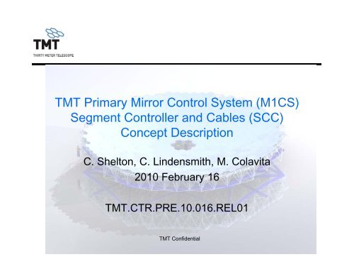
TMT Primary Mirror Control System (M1CS)<br />
Segment Controller and Cables (<strong>SCC</strong>)<br />
Concept Description<br />
C. Shelton, C. Lindensmith, M. Colavita<br />
2010 February 16<br />
TMT.CTR.PRE.10.016.REL01<br />
TMT Confidential
Note<br />
This presentation is intended to provide additional<br />
reference background information only. The <strong>SCC</strong><br />
Architectural Concept Document,<br />
TMT.CTR.10.010.DRF01, shall take precedence over<br />
any information provided in this presentation<br />
TMT Confidential<br />
2
Introduction<br />
The intent of this presentation is to provide background<br />
material to potential ti suppliers of the M1CS Segment<br />
Controller and Cables (<strong>SCC</strong>).<br />
Background material<br />
– <strong>Thirty</strong> <strong>Meter</strong> <strong>Telescope</strong> overview<br />
– The primary mirror (M1) and its control system (M1CS).<br />
– Segment Control and Cabling (<strong>SCC</strong>)<br />
TMT Confidential<br />
3
<strong>Thirty</strong> <strong>Meter</strong> <strong>Telescope</strong><br />
Astronomy’s Next-generation Observatory<br />
TMT.PMO.PRE.08.012.REL01 4 4<br />
TMT Confidential
TMT Overview<br />
The <strong>Thirty</strong> <strong>Meter</strong> <strong>Telescope</strong> will give astronomers the clearest and<br />
deepest picture of the Universe<br />
This telescope will push the frontier of technology, fully integrating<br />
the latest innovations in precision control, segmented mirror design,<br />
and adaptive optics to correct for the blurring effects of Earth’s<br />
atmosphere.<br />
When combined with the unprecedented light-collecting area of the<br />
primary mirror, TMT will be the most capable and sophisticated<br />
telescope ever constructed.<br />
TMT Confidential<br />
5 5
<strong>Telescope</strong> Optics<br />
M1 System<br />
M2 System<br />
M3 System<br />
TMT Confidential<br />
6
The TMT Primary Mirror (M1)<br />
Person<br />
The core technology of TMT is its 492-segment, 30-meter diameter<br />
primary mirror.<br />
There are 492 mirror segments mounted to the mirror cell<br />
Each segment has 3 actuators, 6 edge sensors (2 per intersegment<br />
edge), and 21 warping harnesses (WHs). 7<br />
TMT Confidential
<strong>Telescope</strong> & M1 Cell<br />
TMT Confidential<br />
8
Group of Segments From Above<br />
TMT Confidential<br />
9
Group of Segments From Below<br />
TMT Confidential<br />
10
TMT M1CS Components<br />
Segment 1.4 m<br />
Segment Support<br />
Assembly<br />
Sensor Preamp<br />
prototype<br />
t<br />
Actuators<br />
3 per segment<br />
Sensor Control Bd.<br />
prototype<br />
Drive half<br />
TMT Confidential<br />
Sense half<br />
11
M1 Control System<br />
Man in Mirror Cell<br />
TMT Confidential 12
M1CS Functions<br />
M1CS maintains the shape of the segmented M1<br />
mirror.<br />
M1CS minimizes global M1 distortions caused by:<br />
– Tilting the telescope (gravity sag)<br />
– Temperature<br />
– Wind<br />
– Vibration<br />
– Fabrication and installation errors<br />
M1CS has<br />
– Edge sensors and actuators to correctly position segments<br />
relative to each other, and<br />
– Warping harnesses, to correctly shape individual segments.<br />
TMT Confidential<br />
13
Edge Sensors and Actuators<br />
Edge sensors and actuators move the 492 mirror segments<br />
relative to each other.<br />
The edge sensors report displacement, tilt, and the gap between<br />
adjacent segments. The actuators move each segment in piston, tip,<br />
and tilt.<br />
The edge sensors are to have noise better than 5nm noise, drift<br />
better than 1nm/C and 1/nm week, to be linear over a 300 um range,<br />
and to be monotonic over a 5 mm range.<br />
The actuators each have a voice coil and a precision linear encoder<br />
operating in a local closed loop, at 5000 Hz update rate. Each<br />
actuator has a stepper motor that offloads the voice coil.<br />
The control laws connecting the 2772 sensors to the 1496 actuators<br />
are implemented in “Node Boxes” and in the “Global Loop<br />
Controller”<br />
.<br />
The update rate for positioning the segments is 20 Hz.<br />
TMT Confidential<br />
14
Warping Harnesses<br />
Warping harnesses (WHs) bend each segment to its optically<br />
perfect shape.<br />
There are 21 WHs per segment, each with a stepper motor and a<br />
strain gauge<br />
There are 3 temperature t sensors per each segment<br />
Control of these is split across 3 WH Boxes, each handling 7<br />
stepper/strain gauge pairs and a temperature sensor.<br />
The strain gauges just report applied force back to software. There<br />
is no local closed-loop control of the motor.<br />
WHs are adjusted no more than 10x per night, possibly much less<br />
frequent. The WHs are only powered up during these adjustments.<br />
t<br />
Only one motor / strain gauge pair is powered up and addressed at a<br />
time, per WH Box. This means both the motor and strain gauge<br />
connections can be analog multiplexed to a single driver per WH<br />
Box.<br />
15<br />
TMT Confidential
M1 Control System<br />
<strong>SCC</strong> Hierarchy<br />
The Global Loop Controller (GLC), in a environmentally controlled<br />
computer room, connects to a Power and Signal Unit (PSU) on the<br />
telescope<br />
The PSU connects to six Sector Hubs<br />
Each Sector Hub connects to 14 Node Boxes. There are 84 Node<br />
Boxes.<br />
Each Node Box connects to 5 or 6 segments. There are 492<br />
segments.<br />
Each segment has 3 actuators. There are 1476 actuators.<br />
Each segment has 6 drive-half and 6 sense-half edge sensors.<br />
There are 2772 edge sensors pairs (drive plus sense).<br />
Each segment has 21 WHs. There are 13,284 WHs<br />
Each segment has 3 temperature sensors. There are1476<br />
temperature sensors.<br />
There are 82 spare segments each with sensors, WHs, temperature<br />
TMT Confidential<br />
sensors, and cabling.<br />
16
<strong>SCC</strong> Components<br />
and dRequired dQuantities<br />
Table 1. Quantities of <strong>SCC</strong> components.<br />
Total for<br />
telescope<br />
Total<br />
including<br />
7th sector<br />
Total with<br />
spares<br />
A1. Power and signal unit 1 1 1<br />
A2. Power and signal cabling 1 1 1<br />
B1. Sector hub 6 6 6<br />
B2. Sector hub cabling 6 6 6<br />
C1. Node box 84 84 88<br />
C2. Node cabling 84 84 88<br />
D1. Segment lower box 492 492 517<br />
D2. Segment actuator box 1476 1476 1550<br />
D3. Segment lower cabling 492 492 517<br />
D10. Segment upper box 492 574 603<br />
D11. Segment warping harness box 1476 1722 1808<br />
D12. Segment sensor preamp 2772 3234 3396<br />
D13. Segment upper cabling 492 574 603<br />
The <strong>SCC</strong> does not include segment actuators, edge sensors,<br />
WH motors TMT or Confidential strain gauges<br />
17
Cabling and Connectors Quantity<br />
Number and type<br />
of conductors,<br />
per cable<br />
Source<br />
Destination<br />
sh hielded twisted pair<br />
u nshielded twisted pair<br />
d iscrete wires<br />
co oax<br />
Overall shield<br />
C onnectors per cable<br />
le ength(m)<br />
Moving Frame Mounted - must be<br />
vacuum compatible<br />
Seg Upper Box Seg Sensor Drive 2 2 0.80 * 3,234 4 12,936 10,349 6,468<br />
Seg Sensor Preamp Seg Upper Box 2 2 1 2 0.80 * 3,234 7 22,638 18,110 6,468<br />
WH motor WH Box 4 1 1 0.25 21 12,054 Wires are part of motor 5 60,270 15,068 12,054<br />
WH strain gauge WH Box 4 1 1 0.40 21 12,054 Wires are soldered to strain gauge 5 60,270 24,108 12,054<br />
Temp Sensors WH Box 1 1 0.40 3 1,722 Wires are soldered to temp sensor 3 5,166 2,066 1,722<br />
WH Box Seg Upper Box 4 1 2 0.50 3 1,722 9 15,498 7,749 3,444<br />
Qty per segment<br />
Total<br />
Qty<br />
Notes<br />
onductors per cable<br />
C<br />
ubtotal Conductors<br />
S<br />
opper Length (m)<br />
C<br />
ubtotal Connectors<br />
S<br />
Fixed Frame Mounted Shielded Cat5e or Cat6 cable with RJ45 IP65 connectors is acceptable for these<br />
Seg Upper Box Seg Lower Box 4 1 2 0.4 1<br />
This cable is demated/mated at the<br />
Segment Upper Box end during<br />
492 segment exchange 9 4,428 1,771 984<br />
Segment Actuator Seg Lower Box 4 1 2 0.6 3 1,476 9 13,284 7,970 2,952<br />
Cell Floor Mounted Shielded Cat5e or Cat6 cable with RJ45 IP65 connectors is acceptable for these<br />
Seg Lower Box Node Box 4 1 2 5.5 1 492 Length is 3-7m, average is shown 9 4,428 24,354 984<br />
Node Box Sector Hub 8 2 4 6 84 Length is 2-10m, average is shown 18 1,512 9,072 336<br />
Sector Hub Power & Sig Unit 8 3 2 4 90 6 Length is 80-100m, average is shown 21 126 11,340 24<br />
Number of segments 492 Number of Conductors 200,556<br />
Number of spare segments 82<br />
Total Copper Length (m)<br />
Number of Node Boxes 84<br />
(<strong>SCC</strong> Provided) 92,782<br />
Total Connectors<br />
Number of Edge Sensors 2,772 coax = coaxial cable<br />
(<strong>SCC</strong> Provided) 23,382<br />
Total Cables 36,570 * Most Segments have 6 Edge Sensors - some have fewer<br />
Cables procured through <strong>SCC</strong><br />
TMT Confidential<br />
Cables procured elsewhere<br />
18
Location of Sector Hubs<br />
and dPower and dSignal lUnit<br />
One of six Sector Hubs<br />
on back of mirror cell<br />
One of six Sector Hubs<br />
on back of mirror cell<br />
YM1<br />
SECTOR-B<br />
SECTOR-A<br />
SECTOR-C<br />
1<br />
2<br />
3<br />
4<br />
5<br />
15 21 55<br />
45 66<br />
36 56<br />
29 47 68<br />
37 57<br />
28 46 67<br />
10 22 38 58 77<br />
6 16 30 48 69<br />
11 23 39 59 78<br />
7<br />
8<br />
17<br />
18<br />
31<br />
32<br />
49<br />
50<br />
70<br />
71<br />
12 24 40 60 79<br />
13 25 41 61 80<br />
9 19 33 51 72<br />
14 26 42 62 81<br />
20 34 52 73<br />
27 43 63 82<br />
35 53 74<br />
44 64<br />
54 75<br />
65<br />
76<br />
SECTOR-F<br />
XM1<br />
SECTOR-D<br />
SECTOR-E<br />
Ø30m<br />
Power and<br />
Signal Unit(1x)<br />
View from Sky<br />
TMT Confidential<br />
19
Node Box Locations<br />
Node boxes (84x)<br />
TMT Confidential 20
Segment-to-Node-Box to Mapping<br />
The primary mirror is comprised of 6<br />
identical sectors. One sector is<br />
shown.<br />
Each sector has 82 mirror<br />
segments, for 492 total segments.<br />
Each sector has 14 Node Boxes, for<br />
84 total Node Boxes.<br />
In each sector—<br />
12 Node Boxes control 6 segments<br />
2 Node Boxes control 5 segments.<br />
A possible mapping of segments to<br />
Node Boxes is shown by the color<br />
coding.<br />
The Node Boxes are shown as red<br />
squares. 21<br />
TMT Confidential
Block Diagram of <strong>SCC</strong> components<br />
on the Primary Segment Assembly<br />
Actuators<br />
Warping harnesses & temp sensors<br />
C2<br />
D2.1<br />
Actuator<br />
Board<br />
D2.2<br />
Actuator<br />
Board<br />
D1<br />
Lower Box<br />
D2.3<br />
Actuator<br />
Board<br />
D11.1<br />
WH Box<br />
D13<br />
Upper cabling<br />
D11.2<br />
WH Box<br />
D10<br />
U pper Box<br />
D11.3<br />
WH Box<br />
…<br />
Edge-<br />
Sensor<br />
drive<br />
blocks<br />
1…6<br />
D3<br />
Lower cabling<br />
D12.1<br />
Sensor<br />
Preamp<br />
…<br />
D12.6<br />
Sensor<br />
Preamp<br />
CD. Segment module<br />
Edge-Sensor sense blocks 1…6<br />
Design of D10 Upper Box and Sensor TMT Confidential Preamp D12.1-6 provided by TMT<br />
22
Primary Segment Assembly<br />
Mirror Segment<br />
Mirror Segment<br />
Axial Support Rod<br />
Diaphragm<br />
3 ea Whiffletree Guide Flexure<br />
Warping<br />
Harness<br />
Actuators,<br />
21 ea<br />
Moving Frame<br />
Fixed Frame<br />
Tower<br />
Mirror Cell<br />
Cell floor is 6 ft below<br />
TMT Confidential<br />
Edge sensor<br />
Drive/Sense<br />
Pair<br />
3 ea Actuators<br />
23
Location of <strong>SCC</strong> Components<br />
on Pi Primary Segment tAssembly<br />
Sensor Drive Side<br />
Sensor Sense Side<br />
Sensor Preamp/ADC<br />
Edge sensor<br />
Drive/Sense Pair<br />
Warping<br />
Harness<br />
Actuator<br />
Board (3)<br />
Actuator<br />
Warping Harness Box (3)<br />
Segment Upper Box<br />
TMT Confidential<br />
Segment Lower Box<br />
To Node Box<br />
24
Warping Harness Box Location<br />
Warping<br />
Harness<br />
Boxes<br />
TMT Confidential<br />
25
Detail of Warping Harness<br />
Strain Gauge<br />
Stepper Motor<br />
TMT Confidential<br />
26
Location of Edge Sensors<br />
Segment<br />
Edge Sensor<br />
6 ea. Drive<br />
Central Diaphragm<br />
(bonded to segment)<br />
Drive<br />
Sense<br />
Drive<br />
Sense<br />
6 ea Sense<br />
Axial flexure<br />
assemblies<br />
Sense<br />
27 ea. bonded to<br />
segment<br />
Drive<br />
Drive<br />
Sense<br />
Sense<br />
Drive<br />
Sense<br />
Drive<br />
Alignment Arrow<br />
Points to center of M1<br />
TMT Confidential<br />
27
Vacuum Compatibility<br />
The mirror segments are aluminized (coated) in a vacuum, first on<br />
installation then every two years.<br />
All components on the segment and moving frame must be vacuum<br />
compatible. These are<br />
– Segment Sensor Preamp Assembly<br />
– Warping Harness Boxes each with a Warping Harness Board<br />
– Segment Upper Boxes each with an Segment Upper Board<br />
– Temperature Sensors, with wires and connectors<br />
– Cables<br />
Segment Sensor Preamp Assembly to Segment Upper Box<br />
Segment Sensor Drive Block to Segment Upper Box<br />
Warping Harness Box to Segment Upper Box (3x492).<br />
The Segment Upper Box to Segment Lower Box cable disconnects<br />
at tthe Segment tUpper Box end dfor this coating procedure.<br />
TMT Confidential<br />
28
Segment Installation / Removal<br />
Lifting Talon<br />
Segment<br />
Upper Box<br />
Stays with<br />
Segment<br />
Assembly<br />
Segment<br />
Lower Box<br />
Stays in Place<br />
in Mirror Cell<br />
Segment Lifting Jack<br />
TMT Confidential<br />
29
Primary Segment Assembly<br />
Test Bed<br />
Segment<br />
Upper Box<br />
goes here<br />
Actuator<br />
TMT Confidential<br />
30