Advancement of the Segment Support System - Thirty Meter Telescope
Advancement of the Segment Support System - Thirty Meter Telescope
Advancement of the Segment Support System - Thirty Meter Telescope

You also want an ePaper? Increase the reach of your titles
YUMPU automatically turns print PDFs into web optimized ePapers that Google loves.
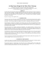
<strong>Advancement</strong> <strong>of</strong> <strong>the</strong> <strong>Segment</strong> <strong>Support</strong> <strong>System</strong> for <strong>the</strong><br />
<strong>Thirty</strong> <strong>Meter</strong> <strong>Telescope</strong> Primary Mirror †<br />
Eric C. Williams* a , Curtis Baffes b , Terry Mast c , Jerry Nelson c , Benjamin Platt b , RJ Ponchione d ,<br />
Eric Ponslet e , Shahriar Setoodeh e , Mark Sirota a , Vince Stephens d , Larry Stepp a , Alan Tubb d .<br />
a TMT Observatory Corporation, 2632 East Washington Blvd, Pasadena, CA, USA 91107;<br />
b Jet Propulsion Laboratory, California Institute <strong>of</strong> Technology, 4800 Oak Grove Dr.,<br />
Pasadena, CA, USA 91109;<br />
c Center for Adaptive Optics, University <strong>of</strong> California, Santa Cruz, USA 95064;<br />
d HYTEC, Inc., 110 Eastgate Drive, Los Alamos, NM, USA 87544<br />
e Formerly HYTEC, Inc.<br />
ABSTRACT<br />
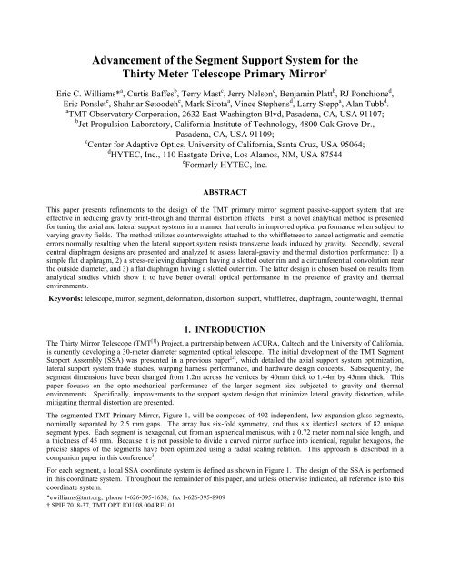
This paper presents refinements to <strong>the</strong> design <strong>of</strong> <strong>the</strong> TMT primary mirror segment passive-support system that are<br />
effective in reducing gravity print-through and <strong>the</strong>rmal distortion effects. First, a novel analytical method is presented<br />
for tuning <strong>the</strong> axial and lateral support systems in a manner that results in improved optical performance when subject to<br />
varying gravity fields. The method utilizes counterweights attached to <strong>the</strong> whiffletrees to cancel astigmatic and comatic<br />
errors normally resulting when <strong>the</strong> lateral support system resists transverse loads induced by gravity. Secondly, several<br />
central diaphragm designs are presented and analyzed to assess lateral-gravity and <strong>the</strong>rmal distortion performance: 1) a<br />
simple flat diaphragm, 2) a stress-relieving diaphragm having a slotted outer rim and a circumferential convolution near<br />
<strong>the</strong> outside diameter, and 3) a flat diaphragm having a slotted outer rim. The latter design is chosen based on results from<br />
analytical studies which show it to have better overall optical performance in <strong>the</strong> presence <strong>of</strong> gravity and <strong>the</strong>rmal<br />
environments.<br />
Keywords: telescope, mirror, segment, deformation, distortion, support, whiffletree, diaphragm, counterweight, <strong>the</strong>rmal<br />
1. INTRODUCTION<br />
The <strong>Thirty</strong> Mirror <strong>Telescope</strong> (TMT [1] ) Project, a partnership between ACURA, Caltech, and <strong>the</strong> University <strong>of</strong> California,<br />
is currently developing a 30-meter diameter segmented optical telescope. The initial development <strong>of</strong> <strong>the</strong> TMT <strong>Segment</strong><br />
<strong>Support</strong> Assembly (SSA) was presented in a previous paper [2] , which detailed <strong>the</strong> axial support system optimization,<br />
lateral support system trade studies, warping harness performance, and hardware design concepts. Subsequently, <strong>the</strong><br />
segment dimensions have been changed from 1.2m across <strong>the</strong> vertices by 40mm thick to 1.44m by 45mm thick. This<br />
paper focuses on <strong>the</strong> opto-mechanical performance <strong>of</strong> <strong>the</strong> larger segment size subjected to gravity and <strong>the</strong>rmal<br />
environments. Specifically, improvements to <strong>the</strong> support system design that minimize lateral gravity distortion, while<br />
mitigating <strong>the</strong>rmal distortion are presented.<br />
The segmented TMT Primary Mirror, Figure 1, will be composed <strong>of</strong> 492 independent, low expansion glass segments,<br />
nominally separated by 2.5 mm gaps. The array has six-fold symmetry, and thus six identical sectors <strong>of</strong> 82 unique<br />
segment types. Each segment is hexagonal, cut from an aspherical meniscus, with a 0.72 meter nominal side length, and<br />
a thickness <strong>of</strong> 45 mm. Because it is not possible to divide a curved mirror surface into identical, regular hexagons, <strong>the</strong><br />
precise shapes <strong>of</strong> <strong>the</strong> segments have been optimized using a radial scaling relation. This approach is described in a<br />
companion paper in this conference 3 .<br />
For each segment, a local SSA coordinate system is defined as shown in Figure 1. The design <strong>of</strong> <strong>the</strong> SSA is performed<br />
in this coordinate system. Throughout <strong>the</strong> remainder <strong>of</strong> this paper, and unless o<strong>the</strong>rwise indicated, all reference is to this<br />
coordinate system.<br />
*ewilliams@tmt.org; phone 1-626-395-1638; fax 1-626-395-8909<br />
† SPIE 7018-37, TMT.OPT.JOU.08.004.REL01
Y M1<br />
Component<br />
<strong>of</strong> Gravity<br />
Y SSA<br />
X M1<br />
X SSA<br />
Z SSA<br />
X SSA<br />
R~62m<br />
Y M1<br />
Actuators (3ea )<br />
45 mm<br />
Y SSA<br />
Z SSA<br />
X SSA<br />
Z SSA<br />
Y SSA<br />
View from Sky<br />
1.44 m<br />
Figure 1<br />
TMT Primary mirror segmentation, nominal segment geometry, and definition <strong>of</strong> global (M1) and<br />
local (SSA) reference frames.<br />
2. SUPPORT SYSTEM DESCRIPTION<br />
To achieve <strong>the</strong> required surface accuracy and stability (less than 20 nm RMS surface figure error from support-induced<br />
deformations) each segment will be supported by a multi-point, passive, near-kinematic system, which is actively<br />
controlled in piston, tip and tilt by a set <strong>of</strong> three linear actuators, and figure-controlled by an automated warping harness.<br />
The segment and support system design are shown schematically in Figure 2.<br />
Mirror <strong>Segment</strong><br />
Mirror Rod Flexures (27 ea)<br />
Diaphragm<br />
Guide Flexure<br />
Whiffletree (3 ea)<br />
Warping Harness<br />
Actuators, 21ea<br />
Moving-frame<br />
Tower<br />
Fixed Frame<br />
Hold-down bolts (3 ea)<br />
Mirror Cell<br />
Adjustable Cell Interface (3 ea)<br />
Figure 2 Schematic <strong>of</strong> <strong>the</strong> TMT primary mirror segment and support system.
The TMT segment support design, shown in Figure 3 and Figure 4, is largely based on concepts developed for o<strong>the</strong>r<br />
segmented mirrors. It is an evolution <strong>of</strong> <strong>the</strong> Keck [4,5] designs, with some features adopted from <strong>the</strong> Sou<strong>the</strong>rn African<br />
Large <strong>Telescope</strong> (SALT [6,7,8,9] ). Even though large segmented telescopes are only about 20 years old, <strong>the</strong> technological<br />
approaches to segment support are relatively well established. Almost every segmented telescope project, since Keck,<br />
has used mechanical whiffletrees for axial support, and a central diaphragm lateral support.<br />
<strong>Segment</strong><br />
Central Diaphragm<br />
(bonded to segment)<br />
Large whiffletree<br />
triangle<br />
Moving-frame<br />
Axial flexure assemblies<br />
27 ea. (bonded to segment)<br />
Edge Sensor<br />
12 ea.<br />
Sheet flexure, 6ea<br />
Small whiffletree triangle<br />
- 3 ea. inner<br />
- 6 ea. outer<br />
Figure 3 Hexagonal mirror segment shown with axial support flexures, central diaphragm, edge sensors<br />
(left), and whiffletrees, sheet-flexures and moving-frame (right).<br />
In contrast with earlier segmented telescopes <strong>of</strong> <strong>the</strong> 10-meter class, such as Keck, <strong>the</strong> much larger size <strong>of</strong> <strong>the</strong> TMT<br />
primary mirror will result in increased gravity-induced deflections <strong>of</strong> <strong>the</strong> primary mirror cell, requiring larger actuator<br />
strokes to maintain segment phasing. The TMT primary mirror segments will also be thinner than previous large<br />
telescopes, making control <strong>of</strong> gravity-induced deflections a more difficult problem. These characteristics favored a<br />
moving-frame support concept [9] which was first introduced by <strong>the</strong> designers <strong>of</strong> <strong>the</strong> Sou<strong>the</strong>rn African Large <strong>Telescope</strong><br />
(SALT). In this approach, an intermediate, stiff moving-frame is used to isolate <strong>the</strong> segment from <strong>the</strong> relatively large<br />
flexure reactions which result from <strong>the</strong> large actuator motions. The moving-frame, supported in-plane by a guideflexure,<br />
absorbs <strong>the</strong>se loads. The whiffletrees are supported laterally by <strong>the</strong> moving-frame, through a set <strong>of</strong> sheetflexures.<br />
The sheet-flexures provide a stiff in-plane load path between <strong>the</strong> whiffletree triangles and <strong>the</strong> moving-frame,<br />
while preserving whiffletree kinematics by way <strong>of</strong> <strong>the</strong>ir out-<strong>of</strong>-plane flexibility.<br />
The whiffletrees, sheet-flexures, and moving-frame are made from aluminum. The 27 rod flexures supporting <strong>the</strong> mirror<br />
and <strong>the</strong> pivots within <strong>the</strong> whiffletrees are stainless steel. The central diaphragm and <strong>the</strong> pucks that connect <strong>the</strong> rodflexures<br />
to <strong>the</strong> glass segment are made from Invar-36. All metal-to-glass connections are made using epoxy adhesive.<br />
Each <strong>of</strong> <strong>the</strong> 82 unique segment types has slightly different dimensions. These differences are accommodated in <strong>the</strong><br />
support system design by small differences in <strong>the</strong> positions <strong>of</strong> <strong>the</strong> whiffletree pivot connections. The results presented in<br />
this paper are for <strong>the</strong> nominal average segment shape, but <strong>the</strong>y are representative <strong>of</strong> <strong>the</strong> performance <strong>of</strong> each type.<br />
An automated warping harness with 21 actuators per segment will provide <strong>the</strong> ability to remotely alter <strong>the</strong> surface figure<br />
<strong>of</strong> each segment to correct for effects such as coating stresses, figuring errors, lateral position errors, seasonal<br />
temperature fluctuations, and through-<strong>the</strong>-thickness variations <strong>of</strong> <strong>the</strong> coefficient <strong>of</strong> <strong>the</strong>rmal expansion <strong>of</strong> <strong>the</strong> glass.<br />
Finally, given <strong>the</strong> unprecedented number <strong>of</strong> segments in TMT (492 + 82 spares), cost control is a major consideration in<br />
<strong>the</strong> design process. The target cost <strong>of</strong> TMT is less than half <strong>of</strong> <strong>the</strong> scaled-up Keck cost. This places very stringent<br />
requirements on fabrication costs in every subsystem. In <strong>the</strong> case <strong>of</strong> <strong>the</strong> SSA, <strong>the</strong> relatively large number <strong>of</strong> replications<br />
<strong>of</strong> an identical assembly presents an opportunity to consider mass production approaches, which will help control costs.
Warping harness<br />
leaf-spring, typ.<br />
<strong>Segment</strong> Position<br />
Actuator<br />
Actuator flexure<br />
Tower Assembly with<br />
Repeatable Interface<br />
Figure 4<br />
Mirror Cell<br />
Fixed Frame<br />
The Polished Mirror Assembly (left) mounts to fixed frame and actuators which are supported by<br />
<strong>the</strong> mirror cell (right). The Polished Mirror Assembly is removed from <strong>the</strong> telescope for recoating<br />
<strong>of</strong> <strong>the</strong> optical surface.<br />
3. PERFORMANCE PREDICTIONS<br />
The performance <strong>of</strong> <strong>the</strong> telescope is strongly influenced by <strong>the</strong> performance <strong>of</strong> <strong>the</strong> SSA subjected to varying gravity and<br />
temperature fields. These effects are considered in <strong>the</strong> design and analysis <strong>of</strong> <strong>the</strong> SSA, and in some cases trade<strong>of</strong>fs <strong>of</strong><br />
one performance characteristic against ano<strong>the</strong>r are required. For example, it is possible to minimize <strong>the</strong> <strong>the</strong>rmal<br />
distortion response <strong>of</strong> <strong>the</strong> segment at <strong>the</strong> expense <strong>of</strong> <strong>the</strong> lateral gravity performance. The character <strong>of</strong> <strong>the</strong> surface errors<br />
is also an important factor in assessing <strong>the</strong> relative merit <strong>of</strong> a particular design. For example, low spatial frequency<br />
errors are more easily tolerated because <strong>the</strong>y impact <strong>the</strong> seeing-limited performance to a lesser degree than high<br />
frequency errors <strong>of</strong> <strong>the</strong> same RMS magnitude. Similarly, <strong>the</strong> telescope Adaptive Optics system has <strong>the</strong> ability to<br />
compensate for low spatial frequency errors, but not for higher frequency errors. Thermal distortion errors typically<br />
contain a significant component <strong>of</strong> focus which is better tolerated than higher frequency errors from axial or lateral<br />
gravity print-through.<br />
TMT intends to final-figure and acceptance-test segments after <strong>the</strong>y are attached to <strong>the</strong>ir support systems, with <strong>the</strong><br />
segments zenith-pointing, and at <strong>the</strong> mean observing temperature. By figuring in this manner, <strong>the</strong> distortion due to axial<br />
gravity and assembly pre-stresses can be removed, along with a significant portion <strong>of</strong> <strong>the</strong> <strong>the</strong>rmal distortion. Therefore,<br />
all performance predictions are relative to <strong>the</strong> final-figured condition. This also implies that <strong>the</strong> axial surface error<br />
springs back as <strong>the</strong> segment is inclined from <strong>the</strong> local zenith (ζ SSA =0) as [1-cos(ζ SSA )], with <strong>the</strong> lateral print-through<br />
increasing from zero at <strong>the</strong> zenith in proportion to [sin(ζ SSA )]. Thermal distortion is proportional to <strong>the</strong> temperature<br />
difference between <strong>the</strong> acceptance test temperature and <strong>the</strong> segment temperature during observing.<br />
3.1 <strong>System</strong>-level Finite Element Simulations<br />
A system-level finite element model, Figure 5, was developed to provide an integrated approach to assessing <strong>the</strong> optical<br />
performance, strength, and stability <strong>of</strong> <strong>the</strong> SSA. The system model, developed using FEMAP [10] and solved using NX-<br />
NASTRAN [11] , captures <strong>the</strong> following important effects which improve <strong>the</strong> quality <strong>of</strong> predictions:<br />
• Combined interaction <strong>of</strong> <strong>the</strong> axial and lateral support systems<br />
• Compliance <strong>of</strong> <strong>the</strong> many structural components, important for optical and dynamic performance predictions
• Aggregate <strong>the</strong>rmal expansion (axial and radial) <strong>of</strong> <strong>the</strong> support systems<br />
• Warping harness stiffening <strong>of</strong> <strong>the</strong> whiffletree mechanism, making <strong>the</strong> system less kinematic<br />
• Mirror cell top chord members and <strong>the</strong> SSA fixed frame<br />
The system model reflects <strong>the</strong> preliminary design, incorporating an optimized 27-point axial support topology and<br />
central diaphragm lateral support. The system model is a high fidelity representation <strong>of</strong> <strong>the</strong> preliminary design,<br />
constructed to ensure that all important effects and interactions are represented.<br />
Mirror <strong>Segment</strong><br />
SSA Whiffletree<br />
SSA Fixed Frame<br />
Mirror Cell Top Chord<br />
Figure 5 <strong>System</strong>-level finite element model <strong>of</strong> segment, SSA, actuators, and mirror cell.<br />
3.2 Axial support performance<br />
A comprehensive investigation and systematic numerical optimization [2] lead to <strong>the</strong> selection <strong>of</strong> <strong>the</strong> 27-point axial<br />
support whiffletree for <strong>the</strong> previous 1.2m segment. The motivations for <strong>the</strong> 27-point topology, shown in Figure 6, were<br />
tw<strong>of</strong>old: 1) <strong>the</strong> axial support print-through surface error could be economically minimized, and 2) <strong>the</strong> warping harness<br />
performance, based on <strong>the</strong> 27 point whiffletree, satisfied performance requirements. Whiffletrees having fewer support<br />
points, or o<strong>the</strong>r arrangements <strong>of</strong> <strong>the</strong> 27-points, did not perform as well. <strong>Support</strong> systems with more than 27 points<br />
require an additional whiffletree layer, which can improve performance but at significant cost in terms <strong>of</strong> part count,<br />
complexity, and production expense.<br />
Since <strong>the</strong> publication <strong>of</strong> <strong>the</strong> previous studies [2] , <strong>the</strong> segment size was increased from 1.2m to 1.44m to reduce<br />
manufacturing cost and part count, improve telescope reliability, and lower <strong>the</strong> long-term operating cost <strong>of</strong> <strong>the</strong><br />
observatory. Simultaneously, with <strong>the</strong> size increase, a decision was made to increase <strong>the</strong> thickness <strong>of</strong> <strong>the</strong> segments to 45<br />
mm. It was recognized that this combination <strong>of</strong> size and thickness would result in slightly increased surface figure error<br />
compared to <strong>the</strong> previous design. This is an expected result, given that for a thin circular plate subject to transverse<br />
bending due to self weight, <strong>the</strong> surface deformation scales as [a 4 /t 3 ], where a is <strong>the</strong> radius and t is <strong>the</strong> thickness.<br />
Therefore, <strong>the</strong> mirror would need to be ~51mm thick to maintain <strong>the</strong> same axial gravity performance as <strong>the</strong> 1.2m by<br />
40mm thick design. The motivations for limiting <strong>the</strong> thickness increase include <strong>the</strong> desire to keep <strong>the</strong> mass and <strong>the</strong>rmal<br />
inertia <strong>of</strong> <strong>the</strong> primary mirror as low as practical, and to also control <strong>the</strong> cost <strong>of</strong> <strong>the</strong> mirror blanks.<br />
Since <strong>the</strong> whiffletree optimization was performed on an idealized finite element model, it was necessary to re-tune <strong>the</strong><br />
whiffletree to account for numerous physical effects that cause <strong>the</strong> real system to behave slightly differently than <strong>the</strong><br />
idealized model. These effects include: mass and stiffness perturbations introduced by <strong>the</strong> central diaphragm support
hole, edge sensor masses, small axial loads transmitted through <strong>the</strong> lateral support central diaphragm, and slight nonkinematic<br />
behavior within <strong>the</strong> whiffletrees. The tuning is accomplished by optimizing <strong>the</strong> in-plane position <strong>of</strong> <strong>the</strong> twelve<br />
whiffletree pivots to minimize axial-gravity (g Z ) induced surface error. (The set <strong>of</strong> twelve pivots consists <strong>of</strong> nine pivots<br />
connecting <strong>the</strong> small whiffletree triangles to <strong>the</strong> large whiffletree triangles, and three pivots that connect <strong>the</strong> large<br />
whiffletree triangles to <strong>the</strong> moving-frame.) The adjustments are calculated using a perturbation technique, and<br />
implemented physically by shifting <strong>the</strong> in-plane locations <strong>of</strong> <strong>the</strong> whiffletree pivots. After tuning <strong>the</strong> axial support system<br />
in this manner, <strong>the</strong> surface error predicted by <strong>the</strong> system-level model is 10.4nm RMS, as shown in Figure 6. As<br />
described previously, this error is figured-out with <strong>the</strong> segment zenith-pointing, and springs-back as <strong>the</strong> segment is tilted<br />
to <strong>the</strong> horizon.<br />
Figure 6<br />
TMT whiffletree support-point topology (left) and predicted surface error resulting from axial<br />
gravity, 1g Z (right). Predicted surface error is 10.4nm RMS and 60nm peak-valley.<br />
Purple = -11nm, Red = +49nm. (Piston/Tip/Tilt subtracted)<br />
3.3 Lateral support performance<br />
Given a thin meniscus mirror laterally supported at one or more discrete points and subject to lateral gravity, <strong>the</strong><br />
curvature <strong>of</strong> <strong>the</strong> neutral axis results in distributed bending moments acting across <strong>the</strong> span. These distributed internal<br />
moments result in bending <strong>of</strong> <strong>the</strong> mirror and distortion <strong>of</strong> <strong>the</strong> optical surface. Additional effects associated with local<br />
attachments can result in additional distortions <strong>of</strong> <strong>the</strong> optic.<br />
A central lateral support can be installed at a given depth below <strong>the</strong> optical surface by machining a pocket (blind hole)<br />
into <strong>the</strong> back <strong>of</strong> <strong>the</strong> mirror. If <strong>the</strong> center support is aligned (in <strong>the</strong> thickness direction, Z) with <strong>the</strong> center <strong>of</strong> mass <strong>of</strong> <strong>the</strong><br />
mirror, <strong>the</strong>re is zero net overturning moment on <strong>the</strong> mirror. If <strong>the</strong> center support is located to ei<strong>the</strong>r side <strong>of</strong> <strong>the</strong> center <strong>of</strong><br />
mass, <strong>the</strong>re will be a net overturning moment that must be reacted. For <strong>the</strong> TMT design, a central diaphragm is bonded<br />
to <strong>the</strong> bottom <strong>of</strong> <strong>the</strong> pocket, forming <strong>the</strong> center support, and <strong>the</strong> whiffletrees react any overturning.<br />
The conventional approach for designing a support system having independent axial and lateral supports is to support<br />
and balance <strong>the</strong> whiffletrees such that <strong>the</strong>y exert no overturning moments onto <strong>the</strong> optic as <strong>the</strong> zenith angle is changed.<br />
All lateral loads are reacted by <strong>the</strong> center support while <strong>the</strong> whiffletrees stabilize <strong>the</strong> optic in tip/tilt, and react any<br />
induced or externally applied overturning moments. Using this approach, <strong>the</strong> optimum diaphragm location is determined<br />
that minimizes <strong>the</strong> surface RMS. This optimum location is <strong>of</strong>fset from <strong>the</strong> neutral axis, slightly closer to <strong>the</strong> concave<br />
optical surface by fractions <strong>of</strong> a millimeter, giving 20.8nm surface RMS due to lateral gravity (1g X and 1g Y ). The<br />
Zernike decomposition <strong>of</strong> this surface shape, calculated using SigFit [12] , is shown in Table 1a. The 20.8 nm RMS result<br />
is not adequate for TMT, so fur<strong>the</strong>r work was performed to find a solution with better performance.<br />
3.4 Interaction <strong>of</strong> axial and lateral supports<br />
In an effort to reduce this print-through error, we consider imposing additional moments into <strong>the</strong> system via whiffletree<br />
imbalance. Notionally, a new optimum can be found that includes some amount <strong>of</strong> whiffletree-based loading that will
eneficially counteract some <strong>of</strong> <strong>the</strong> bending deformation resulting from <strong>the</strong> meniscus shape. To minimize <strong>the</strong><br />
complexity <strong>of</strong> <strong>the</strong> scheme, only moments introduced at <strong>the</strong> large whiffletree triangles are considered. (Note: <strong>the</strong> large<br />
triangles are <strong>the</strong> load spreaders that connect <strong>the</strong> moving-frame to <strong>the</strong> three small triangles in each whiffletree, as shown<br />
in Figure 3). Whiffletree moments introduced at <strong>the</strong> large triangles produce global, low order deformations. When <strong>the</strong><br />
Zernike content <strong>of</strong> <strong>the</strong> whiffletree moment case is examined, Table 1b, a large amount <strong>of</strong> astigmatism and a lesser<br />
amount <strong>of</strong> coma, in <strong>the</strong> ratio <strong>of</strong> approximately 6:1, are seen.<br />
Exploring <strong>the</strong> character <strong>of</strong> <strong>the</strong> 20.8nm surface figure, significant amounts <strong>of</strong> coma and astigmatism are found but in a<br />
different ratio, as shown in Table 1a. As <strong>the</strong> diaphragm axial location and pocket depth are varied, <strong>the</strong> amount <strong>of</strong><br />
astigmatism and coma vary linearly. At one diaphragm location, <strong>the</strong> ratio <strong>of</strong> astigmatism to coma is approximately -6:1,<br />
which is <strong>the</strong> inverse to <strong>the</strong> whiffletree moment effect.<br />
(a) (b) (c) (d)<br />
1gx - Classical 1gx - Re-optimized Magnitude<br />
Optimization (without Whiffletree Moments (with whiffletree Reduction<br />
whiffletree moments) M y = 1 N-m per WT moments) |Mag a | - |Mag c |<br />
Mag. Phi Mag. Phi Mag. Phi ΔMag.<br />
Aberration nm (Deg) nm (Deg) nm (Deg) nm<br />
Input(wrt zero)<br />
Bias -0.05 0.0 0.00 0.0 0.01 0.0 0<br />
Tilt 19.46 -0.1 6.15 180.0 6.80 -0.3 13<br />
Focus -0.28 0.0 0.00 0.0 0.02 0.0 0<br />
Pri Astigmatism -14.97 -45.2 154.10 -45.0 2.27 -48.0 13<br />
Pri Coma -55.48 179.9 24.94 180.0 6.08 -1.2 49<br />
Pri Trefoil 0.09 -16.0 0.00 50.8 0.15 1.1 0<br />
Pri Spherical 0.01 0.0 0.00 0.0 0.01 0.0 0<br />
Sec Astigmatism 1.52 -44.7 17.59 45.0 1.75 44.6 0<br />
Pri Tetrafoil 0.12 18.1 8.63 22.5 0.66 -23.0 -1<br />
Sec Coma 7.66 179.9 10.60 0.0 12.15 0.2 -4<br />
Sec Trefoil 0.03 57.7 0.00 49.2 0.05 -58.7 0<br />
Pri Pentafoil 15.72 -36.0 2.77 -36.0 17.71 -36.0 -2<br />
Sec Spherical -0.07 0.0 0.00 0.0 0.01 0.0 0<br />
Ter Astigmatism 0.14 47.6 1.65 -45.0 0.34 -45.8 0<br />
Sec Tetrafoil 0.03 20.8 0.62 22.5 0.44 22.6 0<br />
Pri Hexafoil 0.08 0.0 0.00 -29.4 0.02 29.5 0<br />
Ter Coma 41.18 -0.1 3.80 180.0 28.54 -0.2 13<br />
Ter Trefoil 0.05 -13.3 0.00 26.9 0.04 -0.9 0<br />
Sec Pentafoil 8.58 -36.0 0.52 -36.0 7.30 -36.0 1<br />
Ter Spherical -0.05 0.0 0.00 0.0 0.02 0.0 0<br />
Qua Astigmatism 0.00 13.4 2.98 45.0 0.61 45.1 -1<br />
Ter Tetrafoil 0.08 21.3 1.77 22.5 0.39 22.7 0<br />
Sec Hexafoil 0.04 1.1 0.00 -21.5 0.01 27.9 0<br />
Table 1<br />
Zernike fit <strong>of</strong> optical surface shape for:<br />
a) 1g x lateral load case for classically optimized design, before correcting with whiffletree<br />
moments (diaphragm located 0.045mm above mirror neutral axis)<br />
b) whiffletree moment case (M Y = 1.0 N-m at three whiffletree locations)<br />
c) 1g x lateral load case for re-optimized design using whiffletree moments<br />
d) Difference between classical results (a) and re-optimized design (c), ΔMag = |Mag a | – |Mag c |.<br />
Figure 7 shows <strong>the</strong> influence <strong>of</strong> diaphragm position on astigmatism, coma, <strong>the</strong> ratio <strong>of</strong> astigmatism to coma, uncorrected<br />
surface RMS (without <strong>the</strong> whiffletree moments included), corrected surface RMS (including <strong>the</strong> whiffletree<br />
moments) and finally, <strong>the</strong>rmal distortion surface RMS. The curve representing corrected RMS shows a new minimum<br />
(~12nm RMS) which is significantly lower than <strong>the</strong> previous minimum (~20.8nm RMS). The new minimum<br />
corresponds to a diaphragm position that is approximately 1.755mm below <strong>the</strong> mid-plane <strong>of</strong> <strong>the</strong> segment. It is noted that<br />
<strong>the</strong> true minimum is not precisely where <strong>the</strong> astigmatism to coma ratio is 6:1. Since <strong>the</strong> gravity-induced surface error<br />
and <strong>the</strong> correcting moments also affect <strong>the</strong> high frequency terms, beyond astigmatism and coma, it is not surprising that
<strong>the</strong> optimum solution is not exactly where <strong>the</strong> ratio is 6:1, but nearby. The Zernike decomposition <strong>of</strong> this new minimum,<br />
(re-optimized) is shown in Table 1c.<br />
The absolute difference in <strong>the</strong> Zernike coefficients between <strong>the</strong> classical result (1a) and <strong>the</strong> re-optimized design (1c) is<br />
shown in Table 1d. Note that this new solution has significantly less Primary Astigmatism, Coma, and Tertiary Coma.<br />
For <strong>the</strong> terms shown, only a few terms show small increases in amplitude. These results demonstrate that <strong>the</strong> approach<br />
significantly reduces global bending at no o<strong>the</strong>r apparent optical consequence.<br />
Uncorrected Zernike Amplitudes (nm)<br />
for 1g lateral (Dashed lines)<br />
20<br />
0<br />
-20<br />
-40<br />
-60<br />
-80<br />
-100<br />
Diaphragm CL at 1.755 mm<br />
Ast./Coma = 4.15<br />
RMS = 12.0 nm<br />
Uncorrected RMS = 20.8 nm (min.)<br />
60<br />
50<br />
40<br />
30<br />
20<br />
10<br />
0<br />
Surface RMS (nm) or Astig/Coma Ratio<br />
(Solid lines)<br />
-120<br />
-1.0 -0.5 0.0 0.5 1.0 1.5 2.0 2.5<br />
Diaphragm centerline (CL) position relative to mirror neutral axis, mm<br />
(Positive direction is away from optical surface)<br />
-10<br />
Coma<br />
RMS (Uncorrected)<br />
Astigmatism/Coma Ratio<br />
Astigmatism<br />
RMS (Corrected by whiffletree moments)<br />
Thermal Distortion RMS for 5 deg C change<br />
Figure 7<br />
Results for 1g X loading: astigmatism, coma, astigmatism to coma ratio (all before correction);<br />
surface RMS corrected and uncorrected. Thermal distortion for 5°C temperature change. All<br />
predictions as a function <strong>of</strong> diaphragm position. (Piston/Tip/Tilt subtracted)<br />
Also shown in Figure 7 is <strong>the</strong> predicted <strong>the</strong>rmal distortion resulting from an iso<strong>the</strong>rmal temperature change applied to<br />
<strong>the</strong> segment and SSA. The <strong>the</strong>rmal distortion arises because <strong>of</strong> <strong>the</strong> coefficient <strong>of</strong> <strong>the</strong>rmal expansion (CTE) mismatch<br />
between <strong>the</strong> SSA and <strong>the</strong> glass. The analysis assumes a 5°C temperature change, which is representative <strong>of</strong> <strong>the</strong><br />
statistical variations about <strong>the</strong> median observing temperature at <strong>the</strong> site. It is noted that <strong>the</strong> <strong>the</strong>rmal distortion decreases<br />
as <strong>the</strong> diaphragm is shifted slightly away from <strong>the</strong> optical surface, over this range <strong>of</strong> diaphragm positions. This effect is<br />
an additional benefit <strong>of</strong> utilizing <strong>the</strong> new minimum.<br />
Ano<strong>the</strong>r design option that was considered is to position <strong>the</strong> diaphragm such that <strong>the</strong> <strong>the</strong>rmal distortion is minimized.<br />
Such a solution was explored, and it was found that <strong>the</strong> <strong>the</strong>rmal distortion could be driven close to zero, but at <strong>the</strong><br />
expense <strong>of</strong> large lateral gravity distortions. Since <strong>the</strong> optical performance <strong>of</strong> <strong>the</strong> telescope is more sensitive to high<br />
frequency errors, such as lateral distortion, it is clear that this approach does not provide a preferred solution for TMT.
3.5 Implementation and analytical verification<br />
The new preferred design has <strong>the</strong> revised diaphragm location, and a set <strong>of</strong> counterweights added to <strong>the</strong> large whiffletree<br />
triangles to produce <strong>the</strong> correcting moments associated with <strong>the</strong> new diaphragm location. The magnitude <strong>of</strong> <strong>the</strong><br />
whiffletree moments required to minimize <strong>the</strong> surface RMS is approximately 0.7 Nm, which corresponds approximately<br />
to a 1 kg mass <strong>of</strong>fset from <strong>the</strong> sheet flexure line-<strong>of</strong>-action by 60mm for each <strong>of</strong> <strong>the</strong> three large triangles. In practice, four<br />
small counterweights will be added to each large whiffletree triangle to produce <strong>the</strong> desired whiffletree moment due to<br />
lateral gravity (g X & g Y ), while preserving <strong>the</strong> tip/tilt balance <strong>of</strong> <strong>the</strong> triangle when subject to axial gravity (g Z ). By<br />
preserving <strong>the</strong> tip/tilt balance, <strong>the</strong> axial gravity performance is essentially unchanged at 10.4nm RMS.<br />
The counterweights are included in <strong>the</strong> system-level model and <strong>the</strong> solution is verified by solving <strong>the</strong> three unit gravity<br />
cases as shown in Figure 8. These results confirm <strong>the</strong> axial gravity response is unchanged, while <strong>the</strong> lateral gravity cases<br />
show significant improvement, with <strong>the</strong> surface RMS reduced to ~12.0 nm.<br />
Axial (-1g Z )<br />
RMS = 10.4 nm, P-V = 60 nm<br />
Purple = -26. nm, Red = +35. nm<br />
Figure 8<br />
Lateral (+1g X )<br />
RMS = 11.99 nm, P-V = 219 nm<br />
Purple = -110. nm, Red = +110. nm<br />
Lateral (+1g Y )<br />
RMS = 11.99 nm, P-V = 219 nm<br />
Purple = -110. nm, Red = +110. nm<br />
Surface distortion plots for three unit gravity load cases from <strong>the</strong> system-level model modified to<br />
have <strong>the</strong> new optimum diaphragm position and large whiffletree triangle counterweights.<br />
(Piston/Tip/tilt subtracted)<br />
4. CENTRAL DIAPHRAGM TRADE STUDIES<br />
The lateral support central diaphragm provides <strong>the</strong> primary lateral load path, supporting <strong>the</strong> segment as <strong>the</strong> telescope tilts<br />
toward <strong>the</strong> horizon. For TMT, <strong>the</strong> Invar diaphragm is bonded directly to <strong>the</strong> glass segment at <strong>the</strong> bottom <strong>of</strong> <strong>the</strong> pocket,<br />
as shown in Figure 3 and Figure 9. This approach was chosen because it is simple, compact, and low cost, not requiring<br />
additional de-coupling flexures between <strong>the</strong> diaphragm and <strong>the</strong> glass. Since <strong>the</strong> segments are fabricated from low<br />
expansion glass, having CTEs near zero, <strong>the</strong> diaphragms are made from Invar, which also has a low CTE. However,<br />
compared to <strong>the</strong> low expansion glass, Invar’s CTE (approximately 1.3 ppm/°C) still causes stress at <strong>the</strong> glass interface,<br />
as well as distortion <strong>of</strong> <strong>the</strong> optical surface as <strong>the</strong> temperature <strong>of</strong> <strong>the</strong> assembly varies during operation, with respect to <strong>the</strong><br />
reference conditions. Several diaphragm concepts have been studied to find a design that moderates <strong>the</strong> CTE mismatch<br />
effects, while providing a stiff, strong load path and acceptable lateral gravity optical performance.
Adhesive layer<br />
Diaphragm<br />
Optical Surface<br />
Diaphragm<br />
Glass<br />
Glass<br />
Moving<br />
Frame<br />
Diaphragm Outer Rim<br />
Figure 9<br />
Cross-section view showing diaphragm outer rim bonded to <strong>the</strong> glass segment at <strong>the</strong> bottom <strong>of</strong> a<br />
machined pocket, and bolted connection between diaphragm center hub and moving-frame.<br />
4.1 Diaphragm Concepts<br />
All <strong>of</strong> <strong>the</strong> diaphragm concepts studied share three basic features. Each has a center hub which provides a stiff, strong<br />
connection to <strong>the</strong> moving-frame via a bolted connection. Each diaphragm also has a thin flexible region that is outboard<br />
<strong>of</strong> <strong>the</strong> hub. This thin region is sized to provide <strong>the</strong> greatest amount <strong>of</strong> axial compliance, while retaining sufficient lateral<br />
stiffness, strength, and elastic stability to support <strong>the</strong> segment during operation and survival events such as handling,<br />
transportation, and seismic. The third common feature is a thickened outer rim that is bonded to <strong>the</strong> glass. The thicker<br />
section is included to improve load transfer, minimize bond peel stress, and ease manufacturing and assembly. There is<br />
a recessed area between <strong>the</strong> glass and <strong>the</strong> thin flexible region to permit <strong>the</strong> diaphragm to deflect during operation without<br />
contacting <strong>the</strong> glass at <strong>the</strong> bottom <strong>of</strong> <strong>the</strong> pocket.<br />
In this discussion, temperature increases affecting <strong>the</strong> system will be referenced, recognizing that a temperature decrease<br />
causes <strong>the</strong> opposite response. When subject to a temperature increase, <strong>the</strong>rmal mismatch loads develop between <strong>the</strong><br />
glass and <strong>the</strong> diaphragm as <strong>the</strong> diaphragm tries to expand radially, while <strong>the</strong> expansion is resisted by <strong>the</strong> low expansion<br />
glass. A design that minimizes <strong>the</strong> effects <strong>of</strong> CTE mismatch is sought. In this light, <strong>the</strong> three diaphragm designs shown<br />
in Figure 10 were considered. All three designs are fabricated from a single piece <strong>of</strong> Invar. Their features and inherent<br />
characteristics will be described, and <strong>the</strong>n <strong>the</strong> analysis results that lead to selecting <strong>the</strong> preferred design for TMT will be<br />
presented.<br />
The first diaphragm concept (Option-1) is a simple, flat diaphragm, having a continuous outer rim. This diaphragm is<br />
<strong>the</strong> simplest and lowest cost design. Analysis shows that it produces <strong>the</strong> largest CTE mismatch loads, and hence largest<br />
stress and optical distortion as <strong>the</strong> temperature changes. When subject to lateral gravity, this diaphragm transfers loads<br />
in an effective manner, helping minimize distortion <strong>of</strong> <strong>the</strong> optical surface.<br />
The second diaphragm concept (Option-2) was developed to reduce <strong>the</strong> CTE mismatch effects by adding two additional<br />
features. First, <strong>the</strong>re is an axisymmetric convolution extending around <strong>the</strong> perimeter near <strong>the</strong> outside diameter <strong>of</strong> <strong>the</strong><br />
flexible region. This flexible convolution allows <strong>the</strong> thin flat region <strong>of</strong> <strong>the</strong> diaphragm to expand radially, without<br />
imparting significant radial forces into <strong>the</strong> glass. Second, <strong>the</strong> outer rim has a pattern <strong>of</strong> radial slots that interrupt <strong>the</strong><br />
hoop continuity <strong>of</strong> <strong>the</strong> outer rim, greatly reducing <strong>the</strong> loads transmitted into <strong>the</strong> glass. The combination <strong>of</strong> <strong>the</strong><br />
convolution and <strong>the</strong> slots results in a very low stress design in terms <strong>of</strong> CTE mismatch. Stiffness and strength are only<br />
slightly degraded for this design, but <strong>the</strong> part is more complex and costly to fabricate. Additionally, <strong>the</strong> slotted rim<br />
results in a set <strong>of</strong> tabs that must be bonded to <strong>the</strong> glass, ra<strong>the</strong>r than <strong>the</strong> continuous rim <strong>of</strong> <strong>the</strong> first concept. Analysis<br />
shows this design to be extremely good from a <strong>the</strong>rmal distortion standpoint, compared to <strong>the</strong> first design, but deficient<br />
when subject to lateral gravity.<br />
The third diaphragm concept (Option-3) is a compromise between <strong>the</strong> first two designs, having a slotted outer rim, but<br />
no convolution. Analysis shows this design to have moderately better <strong>the</strong>rmal distortion, compared to <strong>the</strong> first design,<br />
and essentially <strong>the</strong> same optical performance when subject to lateral gravity.
Option -1<br />
Flat<br />
Option-2<br />
Convolution and Slotted Rim<br />
Option-3<br />
Flat with Slotted Rim<br />
Figure 10 Three lateral support diaphragm Options considered for TMT. Each design is shown from <strong>the</strong><br />
mirror side (top), and cross-sectioned (bottom).<br />
4.2 Component-level analyses<br />
Before <strong>the</strong> system-level optical performance <strong>of</strong> <strong>the</strong>se competing designs can be analyzed and compared, <strong>the</strong> diaphragms<br />
must be sized to transmit <strong>the</strong> design loads. All three diaphragms are buckling-controlled designs. Elastic stability <strong>of</strong> <strong>the</strong><br />
diaphragm is required (shall not buckle) when <strong>the</strong> system is subjected to a 2g static lateral load, and in <strong>the</strong> post-buckled<br />
range, elastic behavior up to 3g is required. Component-level analysis can be used to provide insight into <strong>the</strong><br />
performance and characteristics <strong>of</strong> <strong>the</strong>se designs. In comparing <strong>the</strong> component-level analysis results, two areas <strong>of</strong><br />
performance were observed that are different between <strong>the</strong> designs: <strong>the</strong>rmal-mismatch interface loads, and <strong>the</strong> load-path<br />
for carrying in-plane loads.<br />
4.2.1 Thermally-induced interface loads<br />
Interface loads due to <strong>the</strong>rmal mismatch for Option-1 and Option-2 were calculated from FEA unit-case results by<br />
summing <strong>the</strong> radial component <strong>of</strong> nodal forces at <strong>the</strong> adhesive interface to <strong>the</strong> optic. The Option-2 design (with<br />
convolution and slots) produced an integrated radial force that is one tenth that produced by <strong>the</strong> flat diaphragm, (Option-<br />
1). The reduction <strong>of</strong> <strong>the</strong>rmally induced interface forces results in improved <strong>the</strong>rmal distortion performance for Option-2.<br />
The Option-3 design shows interface forces that are less than <strong>the</strong> Option-1 design, but greater than <strong>the</strong> Option-2 design.<br />
4.2.2 Lateral gravity load path and interface stress<br />
The convolution feature included in <strong>the</strong> Option-2 diaphragm has an effect on <strong>the</strong> in-plane load path and stiffness. As <strong>the</strong><br />
predicted adhesive stress distributions show in Figure 11, <strong>the</strong> load transfer patterns are very different for <strong>the</strong> flat<br />
diaphragms as compared to <strong>the</strong> diaphragm with <strong>the</strong> convolution and slots.<br />
Both flat diaphragms transfer <strong>the</strong> applied load to <strong>the</strong> bond-line along <strong>the</strong> line-<strong>of</strong>-action <strong>of</strong> <strong>the</strong> applied load (<strong>the</strong> 12- and 6-<br />
o’clock positions in <strong>the</strong> figures on <strong>the</strong> left and right). The load is transferred in this manner because <strong>the</strong><br />
tension/compression fields are <strong>the</strong> stiffest load path within <strong>the</strong> diaphragm sheet. The shear load path (at 3- and 9-<br />
o’clock) is less stiff and attracts a significantly smaller portion <strong>of</strong> <strong>the</strong> load (recall <strong>the</strong> shear modulus <strong>of</strong> most metals is<br />
typically ~1/3 <strong>of</strong> <strong>the</strong> tensile modulus).<br />
When <strong>the</strong> convolution is added to <strong>the</strong> diaphragm (Option-2), <strong>the</strong> radial load path (tension/compression) is substantially<br />
decoupled, making <strong>the</strong> shear load path dominant. This results in very little load being transferred at <strong>the</strong> 12- and 6-<br />
o’clock positions, with most <strong>of</strong> <strong>the</strong> load being transferred at <strong>the</strong> 3- and 9-o’clock locations.<br />
We will show in Section 4.3.2 that <strong>the</strong>se different load paths result in important optical consequences for <strong>the</strong> segment<br />
when subject to lateral gravity.
F y = 1N F y = 1N F y = 1N<br />
Option-1 Option-2 Option-3<br />
Figure 11 Diaphragm-to-mirror adhesive stress contour plot (Max shear stress, Pa) resulting from 1N unit<br />
load. Option-1, flat with continuous rim (left), Option-2, convolution and slots (center), and<br />
Option-3, flat with slotted rim (Right)<br />
In addition to <strong>the</strong> difference in <strong>the</strong> load transfer mechanism, <strong>the</strong> convolution also alters <strong>the</strong> in-plane stiffness <strong>of</strong> <strong>the</strong><br />
diaphragm, reducing <strong>the</strong> stiffness by approximately 50% compared to <strong>the</strong> flat diaphragms. The stiffness <strong>of</strong> all three<br />
diaphragm types is adequate for TMT.<br />
Comparing <strong>the</strong> stress magnitudes associated with each design shown in Figure 11, shows that Option-2, with <strong>the</strong><br />
convolution and slots, produces twice <strong>the</strong> adhesive stress at <strong>the</strong> interface to <strong>the</strong> glass. For Option-2, <strong>the</strong> slotted rim bond<br />
tabs near <strong>the</strong> 3- and 6-o’clock locations are subject to shear loads and in-plane torsional moments (M Z ) that produce <strong>the</strong><br />
elevated stresses. The two flat diaphragm options are superior in this regard, since <strong>the</strong> bonds are loaded more uniformly,<br />
resulting in lower stress levels.<br />
4.3 <strong>System</strong>-level performance<br />
In order to determine <strong>the</strong> optical consequences associated with <strong>the</strong>se three diaphragm designs, <strong>the</strong> system-level model<br />
described in Section 3.1 was modified to include each <strong>of</strong> <strong>the</strong> diaphragm designs. After re-optimizing <strong>the</strong> diaphragm<br />
position and adjusting <strong>the</strong> large whiffletree triangle counterweights as described in Section 3.4 <strong>the</strong> predicted <strong>the</strong>rmal<br />
distortion and lateral gravity print-through <strong>of</strong> <strong>the</strong> three designs were compared on a consistent basis.<br />
4.3.1 Thermal distortion<br />
The predicted <strong>the</strong>rmal distortion surface errors are shown in Figure 12. The stress relieving features in Option-2 were<br />
shown to work remarkably well, reducing <strong>the</strong> <strong>the</strong>rmal distortion RMS from 3.19nm/°C (Option-1) to 1.57nm/°C. The<br />
slotted rim added to Option-3 reduces <strong>the</strong> <strong>the</strong>rmal distortion to 2.28nm/°C, which is also a significant improvement.<br />
Option-1<br />
RMS = 3.19nm/°C<br />
PV = 22.1 nm/ºC<br />
Option-2<br />
RMS = 1.57nm/°C<br />
PV = 7.71 nm/ºC<br />
Option-3<br />
RMS = 2.28nm/°C<br />
PV = 13.11 nm/ºC<br />
Figure 12 Thermal distortion predictions for <strong>the</strong> three diaphragm design options, (surface error, nm/°C).<br />
Option-1, flat with continuous rim (left) and Option-2, slots and convolution (center), and Option-<br />
3, flat with slotted rim (right). (Piston/Tip/Tilt subtracted)
The shape <strong>of</strong> <strong>the</strong> mirror <strong>the</strong>rmal distortion is a result <strong>of</strong> two effects; 1) a global focus mode, and 2) a pronounced central<br />
bump caused by <strong>the</strong> diaphragm attachment. The global focus mode results from <strong>the</strong> CTE mismatch <strong>of</strong> <strong>the</strong> whiffletrees<br />
and <strong>the</strong> central diaphragm relative to <strong>the</strong> low expansion glass. The surface pr<strong>of</strong>ile plot, Figure 13, shows <strong>the</strong> <strong>the</strong>rmal<br />
distortion for <strong>the</strong> three designs, plotted along a trajectory between vertices at Y=0. Both flat diaphragms (Options 1 and<br />
3) show a localized central depression (for a temperature increase) superimposed on <strong>the</strong> global focus mode. For Option-<br />
2, with convolution and slots, <strong>the</strong> global focus mode is reduced, and <strong>the</strong> center feature has <strong>the</strong> opposite sign, a bump<br />
ra<strong>the</strong>r than a depression.<br />
10<br />
Surface distortion, nm/°C<br />
5<br />
0<br />
-5<br />
-10<br />
Option-2, with convolution and slots<br />
-15<br />
Option-3, Flat with slotted rim<br />
Option-1, Flat without slots<br />
-20<br />
-0.75 -0.5 -0.25 0 0.25 0.5 0.75<br />
X-coordinate, m<br />
Figure 13 Surface pr<strong>of</strong>ile plot <strong>of</strong> <strong>the</strong>rmal distortion showing center bump superimposed on global focus<br />
mode for three design options. Pr<strong>of</strong>ile trajectory is across segment vertices at Y = 0.<br />
4.3.2 Lateral gravity<br />
For TMT, <strong>the</strong> response to lateral gravity was evaluated assuming any orientation <strong>of</strong> <strong>the</strong> gravity vector relative to <strong>the</strong><br />
segment is possible, since <strong>the</strong> segmentation pattern allows each segment to be installed in its proper location within any<br />
one <strong>of</strong> <strong>the</strong> six sectors which are 60 degrees apart around <strong>the</strong> primary array. Therefore, two orthogonal load cases are<br />
evaluated, aligned with <strong>the</strong> segment coordinate system: 1g X and 1g Y . Although <strong>the</strong> two cases are not identical, because<br />
<strong>of</strong> asymmetry inherent with <strong>the</strong> hexagonal shape, <strong>the</strong> surface deformations are found to be extremely similar in<br />
character, RMS and P-V, so only one set <strong>of</strong> results are presented here (1g X ).<br />
The predicted lateral gravity surface errors for <strong>the</strong> three diaphragm designs are shown in Figure 14. Both <strong>of</strong> <strong>the</strong> flat<br />
diaphragms (Options 1 and 3) show similar results; approximately 12 nm surface error. Somewhat surprisingly, <strong>the</strong><br />
results for Option-2 are substantially worse. It is concluded that <strong>the</strong> different load transfer mechanism for Option-2,<br />
described in Section 4.2.2, causes <strong>the</strong> larger amplitude distortion. It is also noted that <strong>the</strong> shape <strong>of</strong> <strong>the</strong> center bump is<br />
different for Option-2, having a lower spatial frequency and larger peak-to-valley amplitude.<br />
Option-1<br />
RMS = 11.91nm<br />
PV = 217 nm<br />
Option-2<br />
RMS = 16.56nm<br />
PV = 272 nm<br />
Option-3<br />
RMS = 11.99nm<br />
PV = 219 nm<br />
Figure 14 Predicted lateral gravity surface error (x-dir) for each diaphragm type, (nm). Option-1, flat with<br />
continuous rim (left) and Option-2, slots and convolution (center), and Option-3, flat with slotted<br />
rim (right). (Piston/Tip/Tilt subtracted)
The surface deformation pr<strong>of</strong>ile plot, Figure 15, compares <strong>the</strong> character <strong>of</strong> <strong>the</strong> surface deformations from <strong>the</strong> three<br />
diaphragm designs. The amplitude and spatial frequency <strong>of</strong> <strong>the</strong> deformation differs for Option-2 (convolution and slots)<br />
compared to <strong>the</strong> two flat diaphragms (Options-1 and -3). The flat diaphragms introduce two local bending moments into<br />
<strong>the</strong> mirror as load is transferred at <strong>the</strong> 12- and 6-o’clock locations (as discussed in Section 4.2.2). These two moments<br />
are separated along <strong>the</strong> line <strong>of</strong> action, thus giving rise to <strong>the</strong> pair <strong>of</strong> asymmetric bumps. Conversely, Option-2<br />
(convolution and slots) transfers loads into <strong>the</strong> mirror at <strong>the</strong> 3- and 9-o’clock locations (as described in Section 4.2.2),<br />
resulting in a single combined moment with twice <strong>the</strong> magnitude, centered along <strong>the</strong> line <strong>of</strong> action.<br />
Surface distortion, nm<br />
150<br />
100<br />
50<br />
0<br />
-50<br />
-100<br />
Option-2, With convolution and slots<br />
Option-3, Flat with slotted rim<br />
Option-1, Flat without slots<br />
-150<br />
-0.75 -0.5 -0.25 0 0.25 0.5 0.75<br />
X-coordinate, m<br />
Figure 15 Surface pr<strong>of</strong>ile plot <strong>of</strong> lateral gravity distortion for <strong>the</strong> three diaphragm design options. Pr<strong>of</strong>ile<br />
trajectory is across segment vertices at Y = 0, for <strong>the</strong> 1g X load case.<br />
4.4 Preferred diaphragm design<br />
Optical performance results are summarized in Table 2 for <strong>the</strong> three diaphragm designs. Each design has similar Axial<br />
gravity performance, which is expected since all three configurations utilize <strong>the</strong> same axial support systems. Thus, axial<br />
gravity performance is not a differentiating factor in evaluating <strong>the</strong> design options.<br />
Comparing <strong>the</strong> Thermal distortion and Lateral gravity results, Option-2 is extremely good for <strong>the</strong>rmal distortion, but<br />
with significantly higher surface figure error when subject to lateral gravity. Since lateral gravity distortion is <strong>of</strong> high<br />
spatial frequency, <strong>the</strong> optical consequences in <strong>the</strong> telescope are more significant than <strong>the</strong> <strong>the</strong>rmal distortion errors which<br />
contain a significant amount <strong>of</strong> low-order error, as discussed in Section 3. Based on this, <strong>the</strong> lowest lateral gravity<br />
distortion is selected and a slightly larger <strong>the</strong>rmal distortion effect is accepted. Option-3 (flat diaphragm with a slotted<br />
outer rim) is found to be <strong>the</strong> best compromise. This design has good lateral gravity performance, and improved <strong>the</strong>rmal<br />
performance, compared to <strong>the</strong> un-slotted flat diaphragm, Option-1, <strong>the</strong>refore <strong>the</strong> flat diaphragm with <strong>the</strong> slotted outer rim<br />
(Option-3) was chosen as <strong>the</strong> baseline for <strong>the</strong> TMT <strong>Segment</strong> <strong>Support</strong> Assembly.<br />
Diaphragm Type<br />
Thermal distortion<br />
surface error<br />
(nm/°C)<br />
Axial gravity Lateral gravity surface error (nm)<br />
surface error<br />
(1g Z ) (nm) (1g X ) (1g Y )<br />
RMS PV RMS PV RMS PV RMS PV<br />
Option-1,<br />
Flat with un-slotted rim<br />
Option-2,<br />
Convolution & slotted rim<br />
Option-3,<br />
Flat with slotted rim<br />
3.19 22.1 10.37 60.4 11.91 217. 11.77 218.<br />
1.57 7.71 10.69 59.7 16.56 272. 16.66 273.<br />
2.28 13.11 10.37 60.3 11.99 219. 11.83 219.<br />
Table 2<br />
Summary <strong>of</strong> predicted surface errors for three candidate TMT central diaphragm designs.
Ano<strong>the</strong>r design option that we hope to study in <strong>the</strong> future is a blend <strong>of</strong> <strong>the</strong> characteristics <strong>of</strong> Option-2 and Option-3;<br />
essentially a variant <strong>of</strong> Option-2 with a less compliant convolution. Such a design might distribute <strong>the</strong> load more<br />
uniformly around <strong>the</strong> perimeter, resulting in a smoo<strong>the</strong>r pr<strong>of</strong>ile, and might have a <strong>the</strong>rmal distortion that is somewhere<br />
between <strong>the</strong> Option-2 result and <strong>the</strong> Option-3 result.<br />
5. SUMMARY<br />
A novel approach to optimizing <strong>the</strong> lateral support system has been presented that substantially reduces <strong>the</strong> surface<br />
figure error for <strong>the</strong> TMT thin meniscus mirror that is subject to lateral gravity and <strong>the</strong>rmal environments. Three lateral<br />
support central diaphragm designs have also been presented and analyzed. One design, having stress relieving features,<br />
performs extremely well with regard to <strong>the</strong>rmal distortion, but is optically inadequate when resisting lateral gravity.<br />
Finally, <strong>the</strong> preferred central diaphragm was selected for TMT; a flat diaphragm with a slotted outer rim, providing a<br />
good compromise between <strong>the</strong>rmal distortion and lateral gravity performance.<br />
ACKNOWLEDGEMENTS<br />
The authors gratefully acknowledge <strong>the</strong> support <strong>of</strong> <strong>the</strong> TMT partner institutions. They are <strong>the</strong> Association <strong>of</strong> Canadian<br />
Universities for Research in Astronomy (ACURA), <strong>the</strong> California Institute <strong>of</strong> Technology and <strong>the</strong> University <strong>of</strong><br />
California. This work was supported as well by <strong>the</strong> Gordon and Betty Moore Foundation, <strong>the</strong> Canada Foundation for<br />
Innovation, <strong>the</strong> Ontario Ministry <strong>of</strong> Research and Innovation, <strong>the</strong> National Research Council <strong>of</strong> Canada, <strong>the</strong> Natural<br />
Sciences and Engineering Research Council <strong>of</strong> Canada, <strong>the</strong> British Columbia Knowledge Development Fund, <strong>the</strong><br />
Association <strong>of</strong> Universities for Research in Astronomy (AURA) and <strong>the</strong> U.S. National Science Foundation.
REFERENCES<br />
[1] <strong>Thirty</strong> <strong>Meter</strong> <strong>Telescope</strong> (TMT), http://www.tmt.org<br />
[2] E. Ponslet; D. Blanco; M. Cho; T. Mast; J. Nelson; R. Ponchione; M. Sirota; V. Stephens; L. Stepp; A. Tubb;<br />
E. C. Williams, “Development <strong>of</strong> <strong>the</strong> Primary Mirror <strong>Segment</strong> <strong>Support</strong> Assemblies for <strong>the</strong> <strong>Thirty</strong> <strong>Meter</strong><br />
<strong>Telescope</strong>”, E. Atad-Ettedgui; J. Antebi; D. Lemke, Editors, SPIE Proceedings, Vol. 6273, 2006<br />
[3] C. Baffes; T. Mast; J. Nelson; E. Ponslet; V. Stephens; L. Stepp; E. C. Williams, “Primary Mirror <strong>Segment</strong>ation<br />
Studies for <strong>the</strong> <strong>Thirty</strong> <strong>Meter</strong> <strong>Telescope</strong>” SPIE Proceedings, Marseille, 2008.<br />
[4] W. M. Keck Observatory and telescopes, http://www.keckobservatory.org<br />
[5] T. Mast and J. Nelson, “The Status <strong>of</strong> <strong>the</strong> W. M. Keck Observatory and Ten <strong>Meter</strong> <strong>Telescope</strong>,” in Large Optics<br />
Technology, SPIE Proceedings, Vol. 571, 1985<br />
[6] Sou<strong>the</strong>rn African Large <strong>Telescope</strong> (SALT), http://www.salt.ac.za<br />
[7] J. Swiegers and H. Gajjar, “Completion <strong>of</strong> <strong>the</strong> Sou<strong>the</strong>rn African Large <strong>Telescope</strong> (SALT) Primary Mirror<br />
<strong>System</strong>,” in Ground-based <strong>Telescope</strong>s, J. M. Oschmann, Editor, SPIE Proceedings, Vol. 5489, pp. 881-891, 2004<br />
[8] D. A. H. Buckley; J. G. Meiring; J. Swiegers; and G. Swart, “Many segments and a few dollars: SALT solutions<br />
for ELTs,” in Second Bäckaskog Workshop on Extremely Large <strong>Telescope</strong>s, A. L. Ardeberg & T. Andersen,<br />
Editors, SPIE Proceedings, Vol. 5382, pp. 245-256, 2004<br />
[9] D. Blanco et al., “The SALT Mirror Mount: a high performance, low cost mount for segmented mirrors,” in<br />
Future Giant <strong>Telescope</strong>s, J. R. Angel & R. Gilmozzi, Editors, SPIE Proceedings, Vol. 4840, pp. 527-532, 2003<br />
[10] FEMAP TM Users Manual, Version 9.3, UGS Corporation, www.ugs.com<br />
[11] NX NASTRAN TM V5 Users Manual, UGS Corporation, www.ugs.com<br />
[12] SigFit Reference Manual, Version 2004-R1. Sigmadyne Inc, http://www.sigmadyne.com