THE LGSF LASER SYSTEM - Thirty Meter Telescope
THE LGSF LASER SYSTEM - Thirty Meter Telescope
THE LGSF LASER SYSTEM - Thirty Meter Telescope

Create successful ePaper yourself
Turn your PDF publications into a flip-book with our unique Google optimized e-Paper software.
SUB<strong>SYSTEM</strong> REQUIREMENTSDOCUMENTFOR<strong>THE</strong> <strong>LGSF</strong> <strong>LASER</strong> <strong>SYSTEM</strong>TMT.AOS.DRD.09.003.DRF05August 25, 2009
TMT.AOS.DRD.09.003.DRF05 Page 2 of 30REQUIREMENTS DOCUMENT FOR <strong>THE</strong> <strong>LGSF</strong> <strong>LASER</strong> <strong>SYSTEM</strong> August 25, 2009TABLE OF CONTENTS1. INTRODUCTION 51.1 Introduction.............................................................................................................................................51.2 Purpose...................................................................................................................................................51.3 Scope ......................................................................................................................................................51.4 Applicable Documents .........................................................................................................................51.5 Change Record .....................................................................................................................................61.6 Abbreviations .........................................................................................................................................62. OVERALL DESCRIPTION 92.1 Perspective.............................................................................................................................................92.2 System Functions................................................................................................................................102.3 User and Operator Characteristics...................................................................................................102.4 External Interfaces ..............................................................................................................................112.5 Constraints ...........................................................................................................................................112.6 Assumptions and Dependencies......................................................................................................113. SPECIFIC REQUIREMENTS 133.1 General Requirements.......................................................................................................................133.1.1 Standards Requirements...........................................................................................................133.1.2 Sub-system Decomposition Requirements ............................................................................133.2 Environmental Constraints ................................................................................................................133.3 Functional and Performance Requirements...................................................................................143.3.1 Laser Power Requirements.......................................................................................................143.3.2 Laser Beam Performance Requirements ...............................................................................153.3.3 Laser Operation Requirements ................................................................................................163.3.4 Laser System Location and Mass Requirements..................................................................173.3.5 Laser System Power Consumption, Dissipation and Cooling Requirements...................173.3.6 Laser System Emission Requirements ...................................................................................183.3.7 Laser System Vibration Requirements....................................................................................183.3.8 Laser System Software Requirements....................................................................................183.3.8.1 Laser Controller Requirements.........................................................................................193.3.8.2 Laser Sequencer Requirements.......................................................................................203.4 System Attributes Requirements......................................................................................................223.4.1 Reliability Requirements ............................................................................................................223.4.2 Safety and Security Requirements ..........................................................................................233.4.3 Maintainability Requirements....................................................................................................233.5 Access and Handling Requirements ...............................................................................................243.6 Interface Requirements......................................................................................................................253.6.1 <strong>Telescope</strong> Structure (STR) Interface.......................................................................................253.6.2 AO Executive Software (AOESW) Interface ..........................................................................263.6.3 Data Management System (DMS) Interface ..........................................................................273.6.4 <strong>LGSF</strong> Interface ............................................................................................................................274. APPENDIX: <strong>LASER</strong> <strong>SYSTEM</strong> ENVELOPE DRAWING 29
TMT.AOS.DRD.09.003.DRF05 Page 3 of 30REQUIREMENTS DOCUMENT FOR <strong>THE</strong> <strong>LGSF</strong> <strong>LASER</strong> <strong>SYSTEM</strong> August 25, 2009TABLE OF FIGURESFigure 1: <strong>LGSF</strong> Optical Block Diagram ..........................................................................................................10Figure 2: Laser System Control Block Diagram............................................................................................19Figure 3: Laser System Location and Volume..............................................................................................26Figure 4: Laser System Control and Communication Interfaces ...............................................................26
TMT.AOS.DRD.09.003.DRF05 Page 4 of 30REQUIREMENTS DOCUMENT FOR <strong>THE</strong> <strong>LGSF</strong> <strong>LASER</strong> <strong>SYSTEM</strong> August 25, 2009LIST OF TABLESTable 1: Laser System time to inspect and repair after an earthquake ....................................................14Table 2: TMT Observatory Cooling System provided to the Laser System.............................................18Table 3: Laser Controller Functions................................................................................................................20Table 4: Laser Sequencer Functions..............................................................................................................21Table 5: Time to perform Laser System maintenance tasks......................................................................24
TMT.AOS.DRD.09.003.DRF05 Page 5 of 30REQUIREMENTS DOCUMENT FOR <strong>THE</strong> <strong>LGSF</strong> <strong>LASER</strong> <strong>SYSTEM</strong> August 25, 20091. INTRODUCTION1.1 INTRODUCTIONThis is the Laser Guide Star Facility (<strong>LGSF</strong>) Laser System Design RequirementsDocument (DRD). The requirements in this document flow down from the <strong>LGSF</strong> DRDdocument [AD4].1.2 PURPOSEThe purpose of this document is to provide a comprehensive definition of the Laser Systemrequirements.The intended audience for this document is primarily the developers and reviewers of theLaser System.1.3 SCOPEThe Laser System is a sub-system of the TMT <strong>LGSF</strong>. It provides the light sources forgenerating the artificial stars in the sodium layer at 90 – 110 km altitude for the TMTAdaptive Optics (AO) systems.At first light, the Laser System will provide the light sources necessary for generating theartificial stars of the TMT Narrow Field InfraRed Adaptive Optics System (NFIRAOS)asterism. NFIRAOS is a Laser Guide Star (LGS) Multi Conjugate AO (MCAO) system,which feeds up to 3 science instrument ports after sensing and correcting for wavefrontaberrations introduced by atmospheric turbulence and the telescope itself.The Laser System will be eventually upgraded to generate the asterisms for all the futureTMT Laser Guide Star (LGS) AO systems 1 . At least two levels of upgrade are foreseen:- The first upgrade will enable the asterism required by the Multi Object Adaptive Optics(MOAO) instrument. Note that the first light Laser system will enable not only theNFIRAOS MCAO asterism but also the Mid IR Adaptive Optics (MIRAO) and GroundLayer Adaptive Optics (GLAO) asterisms.- The second upgrade will enable the brighter LGS required by the 120x120 orderversion of the NFIRAOS MCAO system. Further upgrades are not known.The scope of this document is limited to the first light Laser System and the first upgrade.Upgrading the Laser System to generate the brighter LGS required by the 120x120 orderversion of the NFIRAOS MCAO system will require different laser technologies.The Laser System does not include either the system to transport and launch the laserbeams to the sky, or the laser safety systems.Section 1 contains information about this document. Section 2 contains information aboutthe <strong>LGSF</strong> Laser system and Section 3 contains the requirements. Paragraphs in Section 3marked as “Discussion” are for information only and are not requirements.1.4 APPLICABLE DOCUMENTS1TMT has defined 4 future LGS AO instruments at the moment: (1) a Mid InfraRed AO (MIRAO) system, which requires 3LGS, (2) a Ground Layer AO (GLAO) system, which requires 5 LGS, (3) a Multi Object AO (MOAO) System, which requires 8LGS and (4) a 120x120 order version of the NFIRAOS MCAO system, which requires 6 brighter LGS.
TMT.AOS.DRD.09.003.DRF05 Page 6 of 30REQUIREMENTS DOCUMENT FOR <strong>THE</strong> <strong>LGSF</strong> <strong>LASER</strong> <strong>SYSTEM</strong> August 25, 2009AD1 Operations Concept Document (OCD), (TMT.OPS.MGT.07.002)AD2 Observatory Requirements Document (ORD), (TMT.SEN.DRD.05.001)AD3 Observatory Architecture Document (OAD), (TMT.SEN.DRD.05.002)AD4 <strong>LGSF</strong> Design Requirement Document, (TMT.AOS.DRD.08.003.REL02)1.5 CHANGE RECORDRevision Date Section ModificationsDRF01 May 7, 2009 All C. Boyer: Initial draftDRF02 May 21, 2009 AllDRF03 June 8, 2009 3.2, 3.3.5,3.4.1, 3.4.2, 3.5and 3.6.1DRF04 June 18, 2009 1.3, 3.2, 3.3.4,3.4.2DRF05 August 24,20092.6, 3.2, 3.3.1,3.3.2, 3.3.3,3.4.1, 3.4.3,3.6.1C. Boyer: Solve TBD and interface definitions,include BE commentsC. Boyer: Modify [REQ-3-LAS-0810], [REQ-3-LAS-0820], [REQ-3-LAS-1440], add [REQ-3-LAS-1560] and [REQ-3-LAS-1570], modify[REQ-3-LAS-1710]. Update section 3.6.1.C. Boyer: Modify [REQ-3-LAS-0200], [REQ-3-LAS-0700], [REQ-3-LAS-1570]C. Boyer: Modify discussions of [REQ-3-LAS-0200] and [REQ-3-LAS-0210].Modify [REQ-3-LAS-0250], [REQ-3-LAS-0310],[REQ-3-LAS-0320], [REQ-3-LAS-0330], [REQ-3-LAS-0350], [REQ-3-LAS-0410], [REQ-3-LAS-0430] and discussion, [REQ-3-LAS-0440] anddiscussion, [REQ-3-LAS-0510] and discussion,[REQ-3-LAS-0520] and discussion, [REQ-3-LAS-0560], [REQ-3-LAS-1440], and discussionof [REQ-3-LAS-1820].Add [REQ-3-LAS-0441], [REQ-3-LAS-0511],[REQ-3-LAS-0521].1.6 ABBREVIATIONSACRS – Azimuth Coordinate SystemAG – Asterism GeneratorAGCM – Asterism Generator Centering MirrorAGPM – Asterism Generator Pointing MirrorAO – Adaptive OpticsAOESW – AO Executive SoftwareAOSQ – Adaptive Optics SequencerAZFA – Azimuth Optical Path Fold ArrayAZOP – Azimuth Optical Path
TMT.AOS.DRD.09.003.DRF05 Page 7 of 30REQUIREMENTS DOCUMENT FOR <strong>THE</strong> <strong>LGSF</strong> <strong>LASER</strong> <strong>SYSTEM</strong> August 25, 2009BDM – Beam Dump MirrorBS – Beam SplitterBTO – Beam Transfer OpticsCW – Continuous WaveDM – Deformable MirrorDMS – Data Management SystemDFA – Deployable Fold ArrayDPA – Deployable Pointing ArrayDRD – Design Requirements DocumentDTRA – Deployable Tracking ArrayECRS – Elevation Coordinate SystemFF – Far FieldFoV – Field of ViewFSM – Fast Steering MirrorGLAO – Ground Layer Adaptive OpticsGUI – Graphical User InterfaceICD – Interface Control DocumentIRMOS – InfraRed Multi Object SpectrographLAS – Laser SystemLGS – Laser Guide Star<strong>LGSF</strong> – Laser Guide Star FacilityLIS – Laser Interlock SystemLSQ – Laser SequencerLSS – Laser Safety SystemLLT – Laser Launch <strong>Telescope</strong>LOM – Laser Output MirrorMCAO – Multi Conjugate Adaptive OpticsMIRAO – Mid IR Adaptive OpticsMOAO – Multi Object Adaptive OpticsMTBF – Mean Time Between FailureN/A – Not ApplicableNFIRAOS – Narrow Field Infrared Adaptive Optics SystemNF – Near FieldOAD – Observatory Architecture DocumentOCD – Operations Concept Document (Level 1 document)OCDD – Operational Concept Definition DocumentORD – Observatory Requirements Document
TMT.AOS.DRD.09.003.DRF05 Page 8 of 30REQUIREMENTS DOCUMENT FOR <strong>THE</strong> <strong>LGSF</strong> <strong>LASER</strong> <strong>SYSTEM</strong> August 25, 2009PAC – Pre-Alignment CameraQA – Quality AssuranceRMS – Root Mean-SquareSFG – Sum Frequency GenerationSHG – Second-Harmonic GenerationSMP – Software Management PlanSTR – <strong>Telescope</strong> StructureTBC – To Be ConfirmedTBD – To Be DefinedTCA – Truss Centering ArrayTFA – Truss Fold ArrayTMT – <strong>Thirty</strong> <strong>Meter</strong> <strong>Telescope</strong>TREL – Truss Relay LensesTRIFA – Tripod Fold ArrayUI – User InterfaceULAO – Up Link AOUPS – Uninterruptible Power SupplyWFS – Wavefront Sensor
TMT.AOS.DRD.09.003.DRF05 Page 9 of 30REQUIREMENTS DOCUMENT FOR <strong>THE</strong> <strong>LGSF</strong> <strong>LASER</strong> <strong>SYSTEM</strong> August 25, 20092. OVERALL DESCRIPTION2.1 PERSPECTIVEThe <strong>LGSF</strong> is composed of 3 main sub-systems:(i)(ii)(iii)The Laser System (LAS), which includes the lasers and all associated controlsystems. The Laser System is located within the (-X ACRS , -Y ACRS ) quadrant of thetelescope azimuth structure (see Figure 3). The Laser System provides the lightsources for generating the artificial stars in the sodium layer at 90 – 110 kmaltitude. The Laser System is the subject of this requirement document.The Beam Transfer Optics (BTO) and Laser Launch <strong>Telescope</strong> (LLT) System,which is responsible for taking the beams from the output of the Laser System andtransferring them across the telescope azimuth structure, up the telescopeelevation structure and then launching them from the LLT located behind the TMTsecondary mirror. The BTO/LLT System is composed of two principal systems: (1)the BTO Optical Path and (2) the <strong>LGSF</strong> Top End, which consists of BTO and LLTcomponents located behind the TMT secondary mirror.The Laser Safety System (LSS), which is itself composed of several sub-systemsdedicated to:a. Protecting people and observatory systems from laser light,b. Protecting aircraft from laser illumination,c. Protecting neighboring telescopes (if any) from laser beams within their field ofview, when necessary.The <strong>LGSF</strong> optical block diagram is given in Figure 1:
TMT.AOS.DRD.09.003.DRF05 Page 10 of 30REQUIREMENTS DOCUMENT FOR <strong>THE</strong> <strong>LGSF</strong> <strong>LASER</strong> <strong>SYSTEM</strong> August 25, 2009Figure 1: <strong>LGSF</strong> Optical Block Diagram2.2 <strong>SYSTEM</strong> FUNCTIONSThe Laser System will provide the following system functions:- Generate the laser light sources required for the NFIRAOS asterism with the properpower level, spectral and temporal characteristics, and image quality.- Be upgradeable to generate the laser light sources needed by the MOAO system.2.3 USER AND OPERATOR CHARACTERISTICSThe Laser System is under the software control of the AO Sequencer (which is a subsystemof the AO Executive Software) during daytime and nighttime operations. Theseoperations include startup, observation, and shutdown operation modes.The users of the Laser System are:- The laser technicians and laser engineers. During commissioning operations, thelaser technicians/engineers perform all the functions required to start the LaserSystem, optimize performance before the LGS observations, monitor and maintainthe Laser System performance during observations and then shutdown the LaserSystem at the end of the LGS observations. During scheduled maintenanceperiods, the laser technicians/engineers perform all the maintenance activitiesrequired by the Laser System.
TMT.AOS.DRD.09.003.DRF05 Page 11 of 30REQUIREMENTS DOCUMENT FOR <strong>THE</strong> <strong>LGSF</strong> <strong>LASER</strong> <strong>SYSTEM</strong> August 25, 2009- The telescope operators. During normal science operations, the lasertechnicians/engineers perform all the functions required to start the Laser Systemduring daytime activities and the telescope operators perform all the functionsrequired to monitor the Laser System performance, and shut down the LaserSystem at the end of observations. All of these operations will be performedthrough the TMT high-level executive software, which will interface automaticallywith the Laser System.2.4 EXTERNAL INTERFACESThe <strong>LGSF</strong> Laser System interfaces with several other observatory systems, including butnot limited to:- The other <strong>LGSF</strong> sub-systems, including:i. The Laser Safety Systemii. The Beam Transfer Optics and Laser Launch <strong>Telescope</strong> System- The <strong>Telescope</strong> Structure (STR)- The AO Executive Software (AOESW)- The Data Management System (DMS)These interfaces are described in more details in section 3.6.2.5 CONSTRAINTSThe Laser System software shall comply with the TMT Observatory software standardsand software development processes to be specified in the TMT Software ManagementPlan (SMP). This plan is not complete at the time, but it will cover the following areas:- The software management process (software life-cycle and milestones, softwaredocumentation, software risk management, configuration control management…).- The software development process (requirements, design, implementation,framework, tools and standards, delivery and maintenance…). Preliminarystandards have been defined in some cases, particularly for the real time systems.Some of these preliminary standards include the choice of:i. Software development/deployment platforms: VxWorks and RT-Linux (RedHat, Novell)ii. Implementation language: C, Embedded C++, JAVA RTS- The software verification and validation process (QA, review process, integrationand test, assembly and verification…).The Laser System shall comply with the safety regulations and processes to be defined inthe TMT Laser Safety Program Document. This document is not complete at this time, butit will cover the following areas:- Safety responsibilities,- Laser safety procedures,- Laser standard operating procedures (operations, controls, registrations, trainingand incident reporting).2.6 ASSUMPTIONS AND DEPENDENCIES
TMT.AOS.DRD.09.003.DRF05 Page 12 of 30REQUIREMENTS DOCUMENT FOR <strong>THE</strong> <strong>LGSF</strong> <strong>LASER</strong> <strong>SYSTEM</strong> August 25, 2009It is assumed that the Laser System is composed of several identical Laser Units and oneLaser Sequencer. Each Laser Unit consists of one Laser Head and one Laser Controller.The number of Laser Units is defined as follows and in requirements [REQ-3-LAS-0310]and [REQ-3-LAS-0330]:- First Light Laser System: six plus one spare (seven total) Laser Units to generatethe NFIRAOS asterism. The First Light Laser System will also generate the MIRAOand GLAO asterisms.- Final Laser System: eight plus one spare (nine total) Laser Units to generate theMOAO asterism.Although only seven Laser Units are required at first light, the Laser System shall bedesigned to be upgradeable to include nine Laser Units.The role of the Laser Sequencer is to coordinate the actions of the multiple LaserControllers and to interface with the AO Sequencer.The Laser Units shall also work as autonomous systems and include for exampleengineering user interfaces for engineering maintenance purposes.
TMT.AOS.DRD.09.003.DRF05 Page 13 of 30REQUIREMENTS DOCUMENT FOR <strong>THE</strong> <strong>LGSF</strong> <strong>LASER</strong> <strong>SYSTEM</strong> August 25, 20093. SPECIFIC REQUIREMENTS3.1 GENERAL REQUIREMENTS3.1.1 Standards Requirements[REQ-3-LAS-0010] The Laser System shall be designed for maintainability, including theuse of standard components where possible, and standardization on metric hardware.[REQ-3-LAS-0020] The Laser System software shall eventually comply, to the greatestextent possible, with the TMT Observatory software standards and software developmentprocess specified in the TMT Software Management Plan.Discussion: The TMT Software Management Plan is not yet available. Please refer tosection 2.5 for further details.3.1.2 Sub-system Decomposition Requirements[REQ-3-LAS-0100] The Laser System shall contain the following sub-systems:- Up to nine Laser Units. Each Laser Unit consists of a Laser Head and a LaserController.- One Laser Sequencer.- And one Laser Cooling System (if necessary).Discussion: The Laser Cooling System is optional. This additional system will be required ifthe Observatory cooling system does not meet the Laser System requirements.3.2 ENVIRONMENTAL CONSTRAINTS[REQ-3-LAS-0200] The Laser System shall be able to operate and meet the requirementsat altitudes varying between 0 meters and 4050 meters.Discussion: The TMT Observatory has selected Mauna Kea, Hawaii for its site.. Thealtitude of the Mauna Kea TMT site is 4050m. In addition, the Laser System will beoperated at the <strong>LGSF</strong> and/or Laser vendor facilities, which are expected to be at muchlower altitudes.[REQ-3-LAS-0210] The Laser System shall be able to operate and meet all therequirements at temperatures varying between 271.4 K (-2 °C) and 295.15 K (22 °C) andat any non-condensing humidity conditions.Discussion: The ambient temperature for Mauna Kea is 271.4 K to 280.8 K (-2 °C to 8 °C).In addition, the Laser System will be operated at typical room temperature at the <strong>LGSF</strong>and/or Laser vendor facilities 295.15 K (22 °C).[REQ-3-LAS-0220] The Laser System shall be able to operate in servicing andmaintenance mode at temperatures varying between 268 K (-5 °C) and 298 K (25 °C) andat any non-condensing humidity conditions.[REQ-3-LAS-0230] The Laser System shall be able to survive without damage theoperational basis survival conditions with temperatures varying between 268 K (-5 °C) to298 K (25 °C) and humidity varying between 0% and 100%.Discussion: Although condensing conditions are specified, it is not expected thatprecipitation is falling within the dome.
TMT.AOS.DRD.09.003.DRF05 Page 14 of 30REQUIREMENTS DOCUMENT FOR <strong>THE</strong> <strong>LGSF</strong> <strong>LASER</strong> <strong>SYSTEM</strong> August 25, 2009[REQ-3-LAS-0240] The Laser System shall be designed to withstand operational basissurvival conditions when there is no power to the observatory.Discussion: The operational basis survival conditions are defined in [REQ-3-LAS-0230].[REQ-3-LAS-0250] The Laser System shall be designed such that loss of power will notcause damage to the Laser System, to the <strong>LGSF</strong> or to the observatory, whatever theoperating state of the Laser System when the loss of power event occurs.Discussion: Note that the Laser System will not be attached to an uninterruptible powersystem (UPS). See section 3.6.1, Services and utilities interface.[REQ-3-LAS-0260] The Laser System shall withstand peak accelerations
TMT.AOS.DRD.09.003.DRF05 Page 15 of 30REQUIREMENTS DOCUMENT FOR <strong>THE</strong> <strong>LGSF</strong> <strong>LASER</strong> <strong>SYSTEM</strong> August 25, 2009Discussion: The NFIRAOS asterism includes six 25W LGS. A spare laser is added forredundancy. Also note that laser power is specified at the output of the Laser Head (i.e.after the output aperture of the Laser Head).[REQ-3-LAS-0320] Each individual Laser Head shall provide a coupling efficiency of atleast 130 photons-m 2 /s/W/ion (TBC) with the mesospheric sodium layer, over a period of atleast 12 hours. The coupling efficiency is based on the following parameters: a LGS beamdiameter at the altitude of the sodium layer of ~0.2m (TBC), a nominal sodium columndensity of 4x10 13 ions/m 2 , and an angle of 21 degrees (Armazones) or 40 degrees (MaunaKea) (TBC) between the direction of the laser propagation and the Earth’s magnetic field.Discussion: The total power level and coupling efficiency yield the required photon return atthe LGS wavefront sensor (WFS) for the estimated optical throughput and sodium layerparameters.Note also that 25W per beacon at this coupling efficiency is required to satisfy the first lightNFIRAOS wavefront error budget at all times, including those times with lower thanaverage sodium column density. At a minimum, a reduced power level of 17W per beaconprovides acceptable performance at a sodium column density of 3x10 13 ions/m 2 , andsatisfies the first light NFIRAOS wavefront error budget during times with median or highersodium column density.[REQ-3-LAS-0330] The Laser System shall be upgradeable to eight plus one spare (ninetotal) 25W Laser Units of the type defined in [REQ-3-LAS-0300].Discussion: The upgraded Laser System will be referenced as the final Laser System inthe rest of the document.[REQ-3-LAS-0340] The short-term (defined as a RMS variability over a 5–minutes period)power stability of each Laser Unit shall be 3% or better.[REQ-3-LAS-0350] The long-term (defined as a peak to peak variation over a 12–hoursperiod) power stability of each Laser Unit shall be 15% with a goal of 10%.3.3.2 Laser Beam Performance Requirements[REQ-3-LAS-0400] Ninety five per cent of the transmitted (far-field) laser beam energy foreach individual Laser Unit shall be contained in a 1.1 times diffraction-limited core, with agoal of 1.01.Discussion: Note that the beam performance requirement is defined at the output of theLaser Head (i.e. after the output aperture of the Laser Head).[REQ-3-LAS-0410] The laser output beams of each individual Laser Unit shall be 98%linearly polarized.Discussion: Specifications regarding the polarization direction will be defined in the nextversion of the document.[REQ-3-LAS-0420] The output beam diameter in the plane of each Laser Head outputaperture shall be 5mm ±0.3mm (TBC) at the 1/e 2 intensity points.Discussion: Specifications regarding the angular divergence of the output beams will bedefined in the next version of the document.[REQ-3-LAS-0430] The output laser beam position stability of each Laser Unit shall be asfollows:- Bias pointing accuracy between high and low power beams: ≤ 25 µrad (TBC) (Peakto peak variation),- Pointing jitter: ≤ 3 µrad RMS (TBC),- Long term drift: ≤ 100 µrad (TBC) (Peak to peak variation defined over a 12-hoursperiod),
TMT.AOS.DRD.09.003.DRF05 Page 16 of 30REQUIREMENTS DOCUMENT FOR <strong>THE</strong> <strong>LGSF</strong> <strong>LASER</strong> <strong>SYSTEM</strong> August 25, 2009- Lateral shift: ≤ 0.5 mm (TBC) (Peak to peak variation).Discussion: See [REQ-3-LAS-0510] and [REQ-3-LAS-0511] for low power beamrequirements. The pointing jitter requirement of 3 µrad corresponds to 1/20 µrad on thesky, which is about 10 milliarcsec.[REQ-3-LAS-0440] Each Laser Unit shall include internal sensors to monitor laser power,wavelength, polarization state and beam quality.Discussion: Far field beam quality is measured in % of closed energy in a diffraction-limitedcore.[REQ-3-LAS-0441] In the case of mode locked CW pulse format lasers, each Laser Unitshall also include internal sensors to monitor line width and temporal pulse format.3.3.3 Laser Operation Requirements[REQ-3-LAS-0500] Each Laser Unit shall include a laser shutter, capable of absorbing thefull laser power indefinitely.Discussion: There shall be no additional heat load presented to the ambient environmentwhen the laser shutter is closed[REQ-3-LAS-0510] Each Laser Unit shall provide a low power beam of 50 milliwattsaverage power to be used for internal <strong>LGSF</strong> alignment and diagnostics.Discussion: The low power beam can be generated with (1) the high power laser operatedin a low power mode, (2) an internal alignment laser or (3) an external laser.[REQ-3-LAS-0511] The pointing accuracy of the low power beam shall be less than100 µrad (TBC).[REQ-3-LAS-0520] The Laser System shall provide a means to tune on and off the sodiumD 2 line with a frequency shift of 10 GHz and a power stability of 3%.[REQ-3-LAS-0521] The time to tune on or off the sodium D 2 line shall be less than1 second with a goal of 100 milliseconds.Discussion: This feature will be used to measure the strength of Rayleigh backscatterduring a LGS WFS calibration, which will be performed for each science observationduring a TMT night (could be as often as every 5 minutes).[REQ-3-LAS-0530] The Laser System shall at least include the following operation modes:- Off mode: The Laser System is powered down.- Shuttered mode: The Laser System is powered on and ready for use but the outputbeams are shuttered with the laser shutters. The low power option can be either onor off.- Run mode: The Laser System is powered on and the output beams are propagatedthrough the <strong>LGSF</strong> Beam Transfer Optics. The low power option can be either on oroff. The wavelength shift can be either on or off.Discussion: Additional operation modes may be defined by the Laser Manufacturer (i.e.intermediate states).[REQ-3-LAS-0540] The Laser System shall start up automatically from a cold start (offmode)to the shuttered mode in no longer than 30 minutes.[REQ-3-LAS-0550] The Laser System shall shutdown automatically from the shutteredmode in no longer than 30 minutes.[REQ-3-LAS-0560] The Laser System shall implement an emergency shutdown, whichshall shutdown the Laser System in less than 0.1 second (TBC) while minimizing thedamage to the Laser Heads.
TMT.AOS.DRD.09.003.DRF05 Page 17 of 30REQUIREMENTS DOCUMENT FOR <strong>THE</strong> <strong>LGSF</strong> <strong>LASER</strong> <strong>SYSTEM</strong> August 25, 2009[REQ-3-LAS-0570] The Laser System shall be able to propagate the laser beams (Runmode) in less than 2 seconds from the shuttered mode.Discussion: The time to open the shutter shall be compliant with current Laser Safetyregulations.[REQ-3-LAS-0580] The laser shutters shall close in 1 second or less.[REQ-3-LAS-0590] The laser shutters shall be designed to close automatically in the eventof a power failure.[REQ-3-LAS-0600] Options shall be provided to control the laser shutters both manuallyvia hardware and remotely via software.3.3.4 Laser System Location and Mass Requirements[REQ-3-LAS-0700] The Laser System shall be located within the (-X ACRS , -Y ACRS ) quadrantof the telescope azimuth structure.Discussion: This means that the Laser System will be operated in a fixed gravity vector.[REQ-3-LAS-0710] The Laser System shall be able to operate with a maximum telescopeangular acceleration around azimuth of 0.2 deg/s 2 .[REQ-3-LAS-0720] The Laser System shall be able to operate with a maximum telescopeangular velocity around azimuth of 2.5 deg/s.[REQ-3-LAS-0730] The Laser System shall be able to operate without a dedicated cleanroom.Discussion: Maintenance of the Laser Unit modules can be performed in a dedicated cleanroom at the observatory if necessary but this clean room is not mounted on the telescopestructure.[REQ-3-LAS-0740] The final Laser System mass shall not exceed 9 tonnes.Discussion: This includes the 9 Laser Units, the Laser Sequencer and the optional LaserCooling System.[REQ-3-LAS-0750] The maximum volume and location of the final Laser System shall beas described in section 3.6.1.[REQ-3-LAS-0760] The output laser beam location of each Laser Head of the final LaserSystem shall be as described in section 3.6.4.3.3.5 Laser System Power Consumption, Dissipation and Cooling Requirements[REQ-3-LAS-0800] The total power consumption of the final Laser System shall notexceed 48,000 Watts.[REQ-3-LAS-0810] The total power dissipation into the surrounding air by the final LaserSystem shall not exceed 200 Watts (TBC).[REQ-3-LAS-0820] The Laser System shall use the chilled liquid cooling system providedby the TMT Observatory. The TMT Observatory cooling system is described in Table 2:
TMT.AOS.DRD.09.003.DRF05 Page 18 of 30REQUIREMENTS DOCUMENT FOR <strong>THE</strong> <strong>LGSF</strong> <strong>LASER</strong> <strong>SYSTEM</strong> August 25, 2009TypeValueCoolant fluidChilled glycol/water -mixture(Percentage glycolby volume 35%(TBC))Supply temperaturesavailable- - 5 °C below predicted night timelow temperature (accuracy ±1.5°C) and/or- Fixed temperatures -9 °C or +7°C (accuracy ± 1.5 °C)Minimum pressure to - 10 bar (TBC) (Typical systemwhich the Laser Systemoperating supply pressure isshall be testedexpected to be approximately 5bar (TBC))Max pressure drop - 1 bar (TBC)Table 2: TMT Observatory Cooling System provided to the Laser SystemDiscussion: If the TMT Observatory Cooling System does not meet the Laser Systemneeds, an additional specialized Laser Cooling System may be provided by the LaserManufacturer.Note that compressed refrigerant (e.g. Hydrochlorofluorocarbon (HCFC)) and pressurizedhelium could also be made available (TBC) to the Laser Vendor if needed.3.3.6 Laser System Emission Requirements[REQ-3-LAS-0900] The Laser System shall not emit light into the enclosure.Discussion: The Laser System shall be designed to prevent generation of stray light duringoperational conditions.[REQ-3-LAS-0910] The Laser System shall be designed to ensure that it will not emitelectromagnetic radiation at any frequency that will adversely interfere with other electronicsystems of the observatory.Discussion: This requirement will be detailed further.3.3.7 Laser System Vibration Requirements[REQ-3-LAS-0920] The vibrations coupled from the Laser System into the telescopestructure shall be minimized.Discussion: Particular attention shall be given to the Laser Cooling System, if such asystem is needed. The use of pumps, and rotating equipment such as fans, motors orother sources of vibrations shall be limited. If necessary, the Laser Cooling System can belocated remotely in an area where vibrations are less of an issue.This requirement will be detailed further.3.3.8 Laser System Software RequirementsDiscussion: The Laser System software requirements are based upon the Laser Systemsub-system decomposition described in sections 2.6 and 3.1.2. Basically, the LaserSystem is composed of several identical Laser Units and one Laser Sequencer. EachLaser Unit consists of a Laser Controller and a Laser Head.The Laser Sequencer synchronizes, controls and monitors the multiple Laser Units. Itconsists of a computer and software system. The Laser Sequencer acts as the principal
TMT.AOS.DRD.09.003.DRF05 Page 19 of 30REQUIREMENTS DOCUMENT FOR <strong>THE</strong> <strong>LGSF</strong> <strong>LASER</strong> <strong>SYSTEM</strong> August 25, 2009interface to the rest of the observatory software systems. The Laser Sequencer isexpected to communicate with the other software observatory systems using the TMTcommon software and protocol, which are not yet defined.The choice of a communication protocol between the Laser Sequencer and the LaserControllers is left to the Laser Vendor.The following block diagram shows the interfaces between the Laser System componentsand the other observatory software systems.Figure 2: Laser System Control Block DiagramThe following sections give the software requirements for the Laser Controllers and theLaser Sequencer.3.3.8.1 Laser Controller Requirements[REQ-3-LAS-1000] Each Laser Controller shall implement an engineering UI.[REQ-3-LAS-1010] Each Laser Controller shall support remote user interfaces.[REQ-3-LAS-1020] It shall be also possible to operate each Laser Controller locally withoutthe need of an external computer or terminal.[REQ-3-LAS-1030] Each Laser Controller shall control and monitor the performance of itsassociated Laser Head.[REQ-3-LAS-1040] At a minimum, each Laser Controller shall implement the commandslisted in Table 3:Configure a Laser Unit (initialize all parameters, includingservo parameters if any)Full start-up sequence for a Laser Unit, implemented eitheras one automatic sequence or as a series of individual stepsFull shutdown sequence for a Laser Unit, implemented eitheras one automatic sequence or as a series of individual stepsOpen and close the laser shutter[REQ-3-LAS-1042][REQ-3-LAS-1044][REQ-3-LAS-1046][REQ-3-LAS-1048]
TMT.AOS.DRD.09.003.DRF05 Page 20 of 30REQUIREMENTS DOCUMENT FOR <strong>THE</strong> <strong>LGSF</strong> <strong>LASER</strong> <strong>SYSTEM</strong> August 25, 2009Turn on and off the low power modeShift the laser central frequency off and back onto the sodiumD2 lineComplete internal diagnostic test sequence for a Laser Unit,implemented either as one automatic sequence or as aseries of individual stepsComplete automated alignment sequence, for a Laser Unit,implemented either as one automatic sequence or as aseries of individual stepsTable 3: Laser Controller Functions[REQ-3-LAS-1050][REQ-3-LAS-1052][REQ-3-LAS-1054][REQ-3-LAS-1056][REQ-3-LAS-1060] At a minimum, each Laser Controller shall be able to monitor/query thefollowing Laser Unit parameters:- Laser Unit status,- Laser Unit power mode,- Laser Unit frequency shift mode,- Laser Unit internal faults and warnings,- Laser Unit output power,- Laser Unit wavelength and line width,- Laser Unit temporal pulse format (for mode locked CW lasers),- Laser Unit polarization state,- Laser Unit beam quality,- And all other appropriate sensor measurements such as temperatures, dew,currents within the Laser Unit…[REQ-3-LAS-1070] Each Laser Controller shall boot or reboot from a cold start in less than30 seconds and be initialized with a default configuration.Discussion: At the end of the boot process, the Laser Controller shall connect to the LaserSequencer, and display the status and health of its Laser Head.The definition of the physical and software protocol to interface the Laser Controllers andthe Laser Sequencer is the responsibility of the Laser Vendor.[REQ-3-LAS-1080] It shall be possible to remotely reset/reboot each Laser Controller.[REQ-3-LAS-1090] The Laser Controllers shall be operable as standalone systems withoutthe need for interface to the Laser Sequencer.[REQ-3-LAS-1100] Each Laser Controller shall gracefully recover from the interruption ofthe network without requiring a reset/reboot.Discussion: In particular, the connection to the Laser Sequencer shall be automatically reestablished.[REQ-3-LAS-1110] The load of each Laser Controller’s processing unit(s) shall not exceed70%.3.3.8.2 Laser Sequencer Requirements[REQ-3-LAS-1200] The Laser Sequencer shall implement an engineering UI.[REQ-3-LAS-1210] The Laser Sequencer shall support remote user interfaces.[REQ-3-LAS-1220] The Laser Sequencer shall also be operable locally without the need ofan external computer or terminal.[REQ-3-LAS-1230] The Laser Sequencer shall control, synchronize and monitor theperformance of the multiple Laser Units.
TMT.AOS.DRD.09.003.DRF05 Page 21 of 30REQUIREMENTS DOCUMENT FOR <strong>THE</strong> <strong>LGSF</strong> <strong>LASER</strong> <strong>SYSTEM</strong> August 25, 2009[REQ-3-LAS-1240] The Laser Sequencer shall be configurable to control any number ofLaser Units up to 9.[REQ-3-LAS-1250] At a minimum, the Laser Sequencer shall implement the commandslisted in Table 4:Configure all lasers, any laser individually, or any possiblecombinationStart all lasers, any laser individually, or any possiblecombinationStop all lasers, any laser individually, or any possiblecombinationOpen or close all laser shutters, any laser shutter individually,or any possible combinationTurn on/off the low power mode of all lasers, any laserindividually, or any possible combinationShift off/back the central line frequency of all lasers, any laserindividually, or any possible combinationTest all lasers, any laser individually, or any possiblecombinationAlign all lasers, any laser individually, or any possiblecombinationTable 4: Laser Sequencer Functions[REQ-3-LAS-1252][REQ-3-LAS-1254][REQ-3-LAS-1256][REQ-3-LAS-1258][REQ-3-LAS-1260][REQ-3-LAS-1262][REQ-3-LAS-1264][REQ-3-LAS-1266]Discussion: Some of these commands may be restricted to authorized personnel.[REQ-3-LAS-1270] At a minimum, the Laser Sequencer shall be able to monitor/query theoverall health and parameters of the Laser System:- Laser Unit status,- Laser Unit power mode,- Laser Unit frequency shift mode,- Laser Unit internal faults and warnings,- Laser Unit output power,- Laser Unit wavelength and line width,- Laser Unit temporal pulse format (for mode locked CW lasers)- Laser Unit polarization state,- Laser Unit beam quality,- And all other appropriate sensor measurements such as temperature, dew, currentwithin the Laser Units…[REQ-3-LAS-1280] The Laser Sequencer shall interface with the AO Sequencer to receivecommands and parameter messages and to return response, status or event messages asdescribed in section 3.6.2.[REQ-3-LAS-1290] The Laser Sequencer shall be available to accept or reject commandsfrom the AO Sequencer at all times. The time to accept or reject a command shall be lessthan 0.1 seconds.[REQ-3-LAS-1300] The Laser Sequencer shall implement a high-level simulation modewhere the interface with the AO Sequencer is simulated.Discussion: The simulation mode shall provide a method for the AO Sequencer to checkcommand flow and sequencing. The commands from the AO Sequencer will be receivedby the Laser Sequencer, and be accepted or rejected but not executed.
TMT.AOS.DRD.09.003.DRF05 Page 22 of 30REQUIREMENTS DOCUMENT FOR <strong>THE</strong> <strong>LGSF</strong> <strong>LASER</strong> <strong>SYSTEM</strong> August 25, 2009[REQ-3-LAS-1310] The Laser Sequencer shall publish a heartbeat variable updated at arate of 1Hz.[REQ-3-LAS-1320] The Laser Sequencer shall interface with the Data ManagementSystem to transfer specific Laser System parameters at a maximum rate of 1 Hz or uponchange as described in section 3.6.3.[REQ-3-LAS-1330] The Laser Sequencer shall boot or reboot from a cold start in less than30 seconds and be initialized with a default configuration.Discussion: At the end of the boot process, the Laser Sequencer shall connect to all LaserControllers, check the health and status of these systems and report the overall LaserSystem health and status to the AO Sequencer.[REQ-3-LAS-1340] It shall be possible to remotely reset/reboot the Laser Sequencer.[REQ-3-LAS-1350] The Laser Sequencer shall be able to operate as a standalone systemand shall work without the need for interfaces to other TMT sub-systems.[REQ-3-LAS-1360] The Laser Sequencer shall gracefully recover from the interruption ofthe network without requiring a reset/reboot.Discussion: In particular, the connections to the Laser Controllers and to the AOSequencer shall be automatically re-established.[REQ-3-LAS-1370] The load of each Laser Sequencer’s processing unit(s) shall notexceed 70%.3.4 <strong>SYSTEM</strong> ATTRIBUTES REQUIREMENTS3.4.1 Reliability Requirements[REQ-3-LAS-01400] The Laser System shall be able to operate and meet all requirementsfor 10 years given preventive and corrective maintenance.Discussion: “Preventive and corrective maintenance” means servicing, repairing, andreplacing components and sub-systems based on their expected lifetime, as opposed totheir failure.[REQ-3-LAS-1410] The unscheduled downtime for the Laser System shall not exceed0.26% of the overall science time budget.Discussion: This corresponds to ~8 hours of the 3000 hours of scheduled scienceobservations per year.[REQ-3-LAS-1420] The unscheduled downtime for the Laser Sequencer shall not exceed0.01% of the overall science time budget.Discussion: This corresponds to ~20 minutes of the 3000 hours of scheduled scienceobservations per year.[REQ-3-LAS-1430] For the final Laser System, the unscheduled individual Laser Unitdowntime budget shall not exceed 0.85% of the overall science time budget.Discussion: The downtime budget for an individual Laser Unit ( p) can be computed via thefollowing formula:NN!P <strong>LASER</strong>=1" # (1" p) i p N"ii!(N " i)!i= N"1!!
TMT.AOS.DRD.09.003.DRF05 Page 23 of 30REQUIREMENTS DOCUMENT FOR <strong>THE</strong> <strong>LGSF</strong> <strong>LASER</strong> <strong>SYSTEM</strong> August 25, 2009where N is the total number of Laser Units (seven for the first light Laser System and ninefor the final Laser System) and P <strong>LASER</strong>=0.0025 is the downtime budget corresponding tothe complete Laser System.The Laser System is considered to have failed, if two or more Laser Units fail at any pointduring the night.!Finally, a downtime budget of 0.85% corresponds to ~26 hours of the 3000 hours ofscheduled science observations per year.[REQ-3-LAS-1440] The Laser Unit Mean Time Between Failure (MTBF) assumingpreventive and corrective maintenance shall be at least ~1400 hours, with the Laser Unitsturned on 12 hours per 24 hours. A Laser Unit failure consists of one of the followingconditions:- The output on axis intensity of the Laser Unit is degraded by more than a factor oftwo as estimated from the ratio of the laser power and the beam qualitymeasurement.- The wavelength is shifted by more than ± 0.5 GHz- The power stability is > 10% (defined as a RMS variability over a 5–minutes period).3.4.2 Safety and Security Requirements[REQ-3-LAS-1500] The Laser System shall comply with all the laser safety regulations tobe described in the TMT Laser Safety Program Document.Discussion: This document is not yet available. Please refer to section 2.5 for furtherdiscussions.[REQ-3-LAS-1510] There shall be a start-up key lock switch located on each Laser Unit.Discussion: It shall not be possible to turn on a Laser Unit unless the key lock is in therequired position.[REQ-3-LAS-1520] Each Laser Unit shall be enclosed in a housing, which prevents laserlight emission except at the location of the output beam aperture.[REQ-3-LAS-1530] The Laser Unit enclosure doors and covers shall be equipped withsafety interlocks to prevent the Laser Units operation with an open door or cover.[REQ-3-LAS-1540] The Laser System shall include all laser safety indicators and warninglabels specified in the TMT Laser Safety Program Document. Indicator lights shall bevisible through all required safety glasses.Discussion: Indicator lights in the dome may not be allowed at night. Indicator sounds maybe used instead, if necessary.[REQ-3-LAS-1550] The Laser System shall implement internal safety features toautomatically shutter the beams and/or perform an emergency system shutdown ifrequired by a sub-system failure.[REQ-3-LAS-1560] A failure of any of the Laser System computing system (software andhardware) shall not cause any damage to the Laser System.[REQ-3-LAS-1570] The Laser System shall be designed to ensure that no fluids, particlesor other materials (e.g., service panel fasteners) can drip or fall onto telescope subsystemsor personnel below the laser system platform.Discussion: This includes but is not limited to coolant and cleaning fluids.3.4.3 Maintainability Requirements
TMT.AOS.DRD.09.003.DRF05 Page 24 of 30REQUIREMENTS DOCUMENT FOR <strong>THE</strong> <strong>LGSF</strong> <strong>LASER</strong> <strong>SYSTEM</strong> August 25, 2009[REQ-3-LAS-1600] The Laser System design shall be modular. Each sub-system of theLaser System shall be an assembly of small modules, each of which can be removed orreplaced by a small team of TMT trained technicians, while the remaining modules remainmounted on the telescope.[REQ-3-LAS-1610] Laser System maintenance requirements shall be minimized andlimited as far as possible to preventive maintenance.Discussion: Preventive maintenance includes but is not limited to:- Inspection;- Checks of functional performance;- Optical re-alignment;- Cleaning optical surfaces;- Component replacements before failure.[REQ-3-LAS-1620] At a minimum, all inspections, checks, and maintenance re-alignmentof the Laser System shall be performed by a small team of TMT trained technicians, whilethe Laser System remains mounted on the telescope.[REQ-3-LAS-1630] Other maintenance tasks shall be performed on-site in a dedicatedLaser Clean Room, by a small team of TMT trained technicians, after removing a smallmodule from the Laser System.Discussion: A small, class 10,000 clean room will be available at the Observatory site forpreventive maintenance and repair/corrective maintenance of the Laser System modules.[REQ-3-LAS-1640] The processes of removing and replacing a Laser System module shallbe repeatable and shall not degrade the performance of the Laser System.[REQ-3-LAS-1650] The time required to perform Laser System maintenance tasks shall beas stated in Table 5:Maintenance tasks Time StaffPreventive maintenance < 2 hours per day One TMT trained techniciantasks not requiring amodule exchangeOther maintenance tasksrequiring a moduleexchange< 2 hours on the telescopeazimuth structure< 4 hours in the dedicatedclean roomTwo TMT trainedtechniciansTable 5: Time to perform Laser System maintenance tasks3.5 ACCESS AND HANDLING REQUIREMENTS[REQ-3-LAS-1700] The Laser System shall be designed for installation/removal into/fromthe <strong>Telescope</strong> Azimuth Structure within 1 day, with a crew of 2 TMT technicians, a craneoperator, and safety personnel.Discussion: A 2 tonne crane will be available to install and remove the components of theLaser System.The installation time does not include the time necessary to assemble and align the lasers.Similarly, the removal time does not include the time necessary to pack the lasers andassociated electronics.
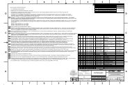
TMT.AOS.DRD.09.003.DRF05 Page 25 of 30REQUIREMENTS DOCUMENT FOR <strong>THE</strong> <strong>LGSF</strong> <strong>LASER</strong> <strong>SYSTEM</strong> August 25, 2009[REQ-3-LAS-1710] To allow rapid installation and removal of the Laser System, the LaserSystem should be designed so that the number of connections is minimized and theconnectors are accessible and easy to mount and dismount.3.6 INTERFACE REQUIREMENTS3.6.1 <strong>Telescope</strong> Structure (STR) Interface[REQ-3-LAS-1800] The Laser System shall have a structural and mechanical interface withthe telescope azimuth structure to be described in the STR to <strong>LGSF</strong> ICD.[REQ-3-LAS-1810] The Laser System shall have an access and handling interface with thetelescope azimuth structure to be described in the STR to <strong>LGSF</strong> ICD.[REQ-3-LAS-1820] The Laser System shall have services and utilities interface with thetelescope azimuth structure to be described in the STR to <strong>LGSF</strong> ICD.Discussion: The STR to <strong>LGSF</strong> ICD is not yet available. The anticipated interfaces betweenthe telescope structure and the Laser System are summarized here:- Structural and mechanical interface:The Laser System will be mounted on the (-X ACRS , -Y ACRS ) quadrant of the telescopeazimuth structure as shown in Figure 3. The allowable envelope of the LaserSystem is illustrated in section 4 (Appendix: Laser System Envelope Drawing). It isexpected that the Laser System will be composed of several components mountedon a platform. Note that this platform is part of the telescope azimuth structure andnot part of the Laser System. The space in the Laser System envelope is entirelydedicated to the Laser System envelope.
TMT.AOS.DRD.09.003.DRF05 Page 26 of 30REQUIREMENTS DOCUMENT FOR <strong>THE</strong> <strong>LGSF</strong> <strong>LASER</strong> <strong>SYSTEM</strong> August 25, 2009- Access and handling interface:Figure 3: Laser System Location and Volume.A 2000kg overhead rail crane will be located above the Laser System envelope forinstallation and removal of the Laser System components. The crane location andreach is shown in the Laser System envelope drawing given in section 4. The LaserSystem platform will be accessible to personnel via stairs from the azimuthwalkway.- Services and utilities interface:i. Both clean and dirty power will be distributed. Note that if necessarygenerator backup of either type of power or clean power that is connectedto a central UPS system could be also available 2 . General utility power willbe made available via industry standard keyed and color coded poweroutlets. Single and Three Phase power will be available; voltages andfrequency characteristics are dependent on the site location (Mauna Kea:480 Y 277 V @ 60Hz; Armazones: 400 Y 230 V @ 50Hz).ii. Copper wire and optical fiber will be available for control andcommunication (including but not limited to the network (control & telemetryLAN) and time-bus as shown in Figure 4).iii. Clean dry compressed air and coolant will be distributed.Figure 4: Laser System Control and Communication Interfaces3.6.2 AO Executive Software (AOESW) Interface[REQ-3-LAS-1900] The Laser Sequencer shall have a software and control interface withthe AO Sequencer to be described in the <strong>LGSF</strong> to AOESW ICD.Discussion: The AO Sequencer controls and synchronizes the actions of the different AOsystems during science observations. The <strong>LGSF</strong> to AOESW ICD is not yet available. Theinterface between the Laser System and the AO Sequencer is summarized here:- The interface shall be implemented via Ethernet.- The Laser System shall interface with the AO Sequencer to receive commands andparameters messages and to send back responses, status and event messagesthrough a protocol to be defined by TMT. The protocol is not yet defined.2Because of the cost of operations, the number of systems connected to generator backup or UPS will be limited.
TMT.AOS.DRD.09.003.DRF05 Page 27 of 30REQUIREMENTS DOCUMENT FOR <strong>THE</strong> <strong>LGSF</strong> <strong>LASER</strong> <strong>SYSTEM</strong> August 25, 2009- At a minimum, the Laser System shall provide the following functions to the AOSequencer:i. Configure the Laser Systemii. Start/shutdown the Laser System (“start” may be restricted to authorizedusers)iii. Open/close the laser shuttersiv. Turn on/off the low power mode of the Laser Systemv. Shift off/back the central frequency of Laser System- At a minimum, the AO Sequencer shall be able to monitor/query the followingparameters:i. Laser System status,ii. Laser System power mode,iii. Laser System frequency shift mode,iv. Laser System faults, warnings, and interlocks,v. Laser System laser parameters…3.6.3 Data Management System (DMS) Interface[REQ-3-LAS-2000] The Laser Sequencer shall have a software and control interface withthe Data Management System (DMS) to be described in the <strong>LGSF</strong> to DMS ICD.Discussion: The Data Management System includes an engineering database. Thepurpose of this interface is to archive Laser System engineering data for maintenancepurposes. The <strong>LGSF</strong> to DMS ICD is not yet available. The interface between the LaserSystem and the DMS is summarized here:- The interface shall be implemented via Ethernet.- The Laser System shall interface with the Data Management System to transfer aset of defined Laser System parameters through a protocol to be defined by TMT, ata rate of 1Hz or upon change. The protocol is not yet defined.- The Laser System shall provide the following time-stamped parameters to the DataManagement System (note that the TMT time bus will be available to the LaserSystem):i. Laser System status,ii. Laser System power mode,iii. Laser System frequency shift mode,iv. Laser System faults, warnings, and interlocks,v. Laser System laser parameters…3.6.4 <strong>LGSF</strong> Interface[REQ-3-LAS-2100] The Laser System shall have a software and control interface with the<strong>LGSF</strong> Laser Interlock System to receive or generate interlock events to be described in the<strong>LGSF</strong> to <strong>LGSF</strong> LAS ICD.Discussion: The <strong>LGSF</strong> to <strong>LGSF</strong> LAS ICD does not yet exist. The interlock interfacebetween the Laser System and the Laser Interlock System (LIS) is summarized here:This interface will be implemented via complementary TTL level signals (TBC). The signalsmust operate in a fail-safe mode so that if a signal line is broken the Laser System shallplace its hardware in a safe state and/or the LIS shall raise the appropriate interlock toother systems.The inputs to the LIS from the Laser System are (one interlock signal per Laser Unit):
TMT.AOS.DRD.09.003.DRF05 Page 28 of 30REQUIREMENTS DOCUMENT FOR <strong>THE</strong> <strong>LGSF</strong> <strong>LASER</strong> <strong>SYSTEM</strong> August 25, 2009- Laser Units status (Off mode, Shuttered mode, Run mode),- Laser shutters state (Open or closed),- Laser Units faults (internal laser faults).The demands from the LIS to the Laser System are (one interlock signal per Laser Unit):- Close the laser shutter,- Perform an emergency shutdown of the Laser Unit.[REQ-3-LAS-2110] The Laser System shall have a mechanical and structural interface withthe Beam Transfer Optics and Laser Launch <strong>Telescope</strong> (BTO/LLT) System to bedescribed in the <strong>LGSF</strong> to <strong>LGSF</strong> LAS ICD.Discussion: The <strong>LGSF</strong> to <strong>LGSF</strong> LAS ICD is not yet available. The interface between theLaser System and the Beam Transfer Optics and Laser Launch <strong>Telescope</strong> (BTO/LLT)System is summarized here:- The Laser System is connected to the BTO Optical Path via a mechanical interface.The exact locations and alignment of the laser output beams at this interface are leftto the Laser Vendor, but are constrained as follows:i. At the plane formed by the Azimuth Optical Path Fold Array shown in theLaser System Envelope Drawing in Appendix 4, the 9 beams of the finalLaser System shall be parallel and form a 3x3 square pattern with a140mm side (70mm between the centers of the beams).ii. For the first light Laser System, 7 of the 9 beams formed by the 3x3 squarepattern will be populated.iii. Only one mirror per beam is allowed between the Laser System and theAzimuth Optical Path Fold Array (AZFA). Note that these Laser outputmirrors and the AZFA are not part of the Laser System, but the placementand alignment of each output mirror may depend upon the Laser Systemlayout.
TMT.AOS.DRD.09.003.DRF05 Page 29 of 30REQUIREMENTS DOCUMENT FOR <strong>THE</strong> <strong>LGSF</strong> <strong>LASER</strong> <strong>SYSTEM</strong> August 25, 20094. APPENDIX: <strong>LASER</strong> <strong>SYSTEM</strong> ENVELOPE DRAWING
TMT.AOS.DRD.09.003.DRF05 Page 30 of 30REQUIREMENTS DOCUMENT FOR <strong>THE</strong> <strong>LGSF</strong> <strong>LASER</strong> <strong>SYSTEM</strong> August 25, 2009