Exhibit B: Specification for M2 Segment Blank - Thirty Meter Telescope
Exhibit B: Specification for M2 Segment Blank - Thirty Meter Telescope
Exhibit B: Specification for M2 Segment Blank - Thirty Meter Telescope

Create successful ePaper yourself
Turn your PDF publications into a flip-book with our unique Google optimized e-Paper software.
SECONDARY MIRROR BLANK<br />
SPECIFICATIONS<br />
TMT.OPT.SPE.07.005.REL02<br />
12 January 2010
TMT.OPT.SPE.07.005.REL01 Page 2 of 20<br />
SECONDARY MIRROR BLANK SPECIFICATIONS 1/12/2010<br />
TABLE OF CONTENTS<br />
1. INTRODUCTION 4<br />
1.1 Purpose ................................................................................................................................................... 4<br />
1.2 Scope ...................................................................................................................................................... 4<br />
1.3 Change Record....................................................................................................................................... 4<br />
1.4 Abbreviations .......................................................................................................................................... 5<br />
1.5 Definitions................................................................................................................................................ 5<br />
2. OVERALL DESCRIPTION 8<br />
2.1 Perspective.............................................................................................................................................. 8<br />
3. SPECIFIC REQUIREMENTS 8<br />
3.1 Material Properties.................................................................................................................................. 8<br />
3.1.1 <strong>M2</strong> <strong>Blank</strong> Material........................................................................................................................... 8<br />
3.1.2 Chemical Resistance ..................................................................................................................... 8<br />
3.1.3 Dimensional Stability...................................................................................................................... 9<br />
3.1.4 Polishing Compatibility ................................................................................................................... 9<br />
3.1.5 Coefficient of Thermal Expansion (CTE)....................................................................................... 9<br />
3.2 Residual Stress.....................................................................................................................................11<br />
3.3 Dimensions ...........................................................................................................................................11<br />
3.4 Surface Condition .................................................................................................................................12<br />
3.5 Fiducial Markings ..................................................................................................................................12<br />
3.6 Inclusions and Defects..........................................................................................................................12<br />
3.6.1 Inclusions......................................................................................................................................12<br />
3.6.2 Surface Chips and Cracks ...........................................................................................................13<br />
4. DOCUMENTATION REQUIREMENTS 14<br />
5. PACKAGING AND DELIVERY 15<br />
6. <strong>M2</strong> BLANK DRAWING 15<br />
7. APPENDICES 17<br />
7.1 CTE Specimen Sampling Geometry....................................................................................................17<br />
7.2 Instantaneous CTE Measurement .......................................................................................................17<br />
7.3 Calculating Effective CTE and Average CTE ......................................................................................18<br />
7.3.1 Effective CTE................................................................................................................................18<br />
7.3.2 Average CTE ................................................................................................................................18<br />
7.4 Calculating CTE Axial Gradient............................................................................................................19
TMT.OPT.SPE.07.005.REL01 Page 3 of 20<br />
SECONDARY MIRROR BLANK SPECIFICATIONS 1/12/2010<br />
TABLE OF FIGURES<br />
Figure 1. Section through the Secondary Mirror Assembly including the Hexapod Positioner and <strong>M2</strong> Mirror<br />
Cell Assembly. .................................................................................................................................................4<br />
Figure 2. Secondary Mirror <strong>Blank</strong> Drawing............................................................................................................16<br />
Figure 4. ΔL/L and Instantaneous CTE measurement data of a hypothetical specimen “n” .............................18<br />
Figure 5. Calculation of Effective CTE and Average CTE of a hypothetical CTE Specimen.............................19<br />
Figure 6. Example of CTE Axial Gradient Calculation .........................................................................................20<br />
LIST OF TABLES<br />
Table 1. Summary of Optical and Dimensional Properties of the <strong>M2</strong> Mirror and <strong>M2</strong> Mirror <strong>Blank</strong> 8<br />
Table 2. Inclusion and Defect Limits 14
TMT.OPT.SPE.07.005.REL01 Page 4 of 20<br />
SECONDARY MIRROR BLANK SPECIFICATIONS 1/12/2010<br />
1. INTRODUCTION<br />
This document defines the mirror blank requirements <strong>for</strong> the Secondary Mirror (<strong>M2</strong>M) of the <strong>Thirty</strong><br />
<strong>Meter</strong> <strong>Telescope</strong> (TMT). The <strong>M2</strong> <strong>Blank</strong> will be fabricated into the solid meniscus <strong>M2</strong> Mirror that is<br />
shown in the Secondary Mirror Assembly (<strong>M2</strong>A) in Figure 1.<br />
HEXAPOD<br />
POSITIONER<br />
<strong>M2</strong> MIRROR<br />
CELL<br />
ASSEMBLY<br />
SECONDARY<br />
MIRROR<br />
Figure 1. Section through the Secondary Mirror Assembly including the Hexapod Positioner and <strong>M2</strong> Mirror<br />
Cell Assembly.<br />
1.1 PURPOSE<br />
This document specifies requirements <strong>for</strong> the Secondary Mirror <strong>Blank</strong> <strong>for</strong> the <strong>Thirty</strong> <strong>Meter</strong> <strong>Telescope</strong><br />
Secondary Mirror.<br />
1.2 SCOPE<br />
This specification defines the requirements <strong>for</strong> the <strong>M2</strong> <strong>Blank</strong> only. The requirements <strong>for</strong> the finished<br />
Secondary Mirror are described in a separate specification.<br />
1.3 CHANGE RECORD<br />
Revision Date Section Modifications<br />
REL01 April 17, 2007 Original release<br />
REL02 Jan. 12, 10 This is the initial version of this specification since<br />
the change of the TMT telescope baseline design
TMT.OPT.SPE.07.005.REL01 Page 5 of 20<br />
SECONDARY MIRROR BLANK SPECIFICATIONS 1/12/2010<br />
1.4 ABBREVIATIONS<br />
CTE Coefficient of Thermal Expansion<br />
CTE e Effective Coefficient of Thermal Expansion<br />
CTE i Instantaneous Coefficient of Thermal Expansion<br />
ºC Degrees Centigrade<br />
ΔL Change in Length<br />
L Length<br />
<strong>M2</strong>A Secondary Mirror Assembly<br />
<strong>M2</strong>CA Secondary Mirror Cell Assembly<br />
<strong>M2</strong>M Secondary Mirror<br />
mm millimeter<br />
MPa megapascal<br />
RMS Root Mean Square<br />
ΔT Change in Temperature<br />
TMT <strong>Thirty</strong> <strong>Meter</strong> <strong>Telescope</strong><br />
1.5 DEFINITIONS<br />
<br />
<br />
<br />
<br />
<br />
<br />
<br />
<br />
<br />
<br />
<br />
Back Surface: The concave surface of the <strong>Blank</strong> that is on the opposite side of the convex<br />
<strong>M2</strong> optical surface<br />
Basic Dimension: A theoretically exact value used to describe the ideal size, profile,<br />
orientation or location of a feature. Geometric Dimensioning and Tolerancing shall be<br />
interpreted per ANSI Y-14.5M-1994.<br />
<strong>Blank</strong>: The <strong>Blank</strong> is the piece of glass or glass-ceramic from which the TMT Secondary<br />
Mirror will be fabricated.<br />
<strong>Blank</strong> Supplier: the manufacturer that will supply the <strong>Blank</strong><br />
Blister: A Blister is a flat void in a seam between boules of material that have been fused<br />
together to make the <strong>Blank</strong>.<br />
Bubbles: See Inclusions.<br />
Chip: A Chip is defined as a hollow depression in the surface of the M3 <strong>Blank</strong>. A ground out<br />
spherical depression shall be considered to be a Chip, as defined in this specification. Chips<br />
occur only on the surface of the <strong>Blank</strong> material. The size of a chip shall be its Mean<br />
Diameter.<br />
Crack: A crack is defined as a separation of the material of the blank. The length of the<br />
crack shall be defined as the longest dimension of the separation area.<br />
Critical Zone: The Critical Zone is defined as the volume of material directly under the<br />
convex surface of the <strong>Blank</strong>. This zone shall be 10mm in thickness, and shall extend over the<br />
surface to within 10mm from the edge, as shown in Figure 2.<br />
CTE Axial Gradient: The CTE Axial Gradient is defined as the slope of the linear least<br />
squares fit of the Operating Range Average CTE <strong>for</strong> each CTE Specimen plotted versus the<br />
axial distance of the measured material from the center of the sag thickness of the <strong>M2</strong> <strong>Blank</strong>.<br />
The center of the sag thickness of the blank and the sign of the axial distance are defined in<br />
Note 9 and in the positive direction of the Z-<strong>Blank</strong> arrow in Figure 2. An example of this<br />
calculation is provided in Appendix 7.4<br />
CTE Lateral Variation: The CTE Lateral Variation is defined as the absolute value of the<br />
difference between the Operating Range Average CTE of all the CTE Specimens of the <strong>M2</strong><br />
<strong>Blank</strong> (averaged together) and the Operating Range Average CTE of each CTE Specimen.
TMT.OPT.SPE.07.005.REL01 Page 6 of 20<br />
SECONDARY MIRROR BLANK SPECIFICATIONS 1/12/2010<br />
<br />
<br />
<br />
<br />
<br />
<br />
<br />
<br />
<br />
<br />
<br />
<br />
<br />
<br />
<br />
CTE Specimen: CTE Specimen is defined as a sample of glass or glass-ceramic material<br />
used to derive the CTE metrics in the <strong>Blank</strong>. CTE Specimens shall be taken from material<br />
immediately adjacent to the <strong>Blank</strong> material. For a <strong>Blank</strong> material whose CTE can be<br />
measured in-situ, references in this document to CTE Specimens shall include in-situ CTE<br />
measurements made at specific locations, where applicable.<br />
Defects: Defects Defects are defined as chips or cracks on the surface or cracks inside the<br />
M3 <strong>Blank</strong> material.<br />
Generating: machining the surfaces of the <strong>M2</strong> <strong>Blank</strong> by fixed-abrasive grinding or similar<br />
technique<br />
Inclusions: Inclusions are defined as any <strong>for</strong>eign matter in the <strong>M2</strong> <strong>Blank</strong> that is not the zeroexpansion<br />
material from which the <strong>M2</strong> <strong>Blank</strong> is made. For purposes of this specification,<br />
Bubbles are considered to be Inclusions.<br />
Instantaneous CTE: Instantaneous CTE is defined as the first derivative with respect to<br />
Temperature of the curve of ΔL/L plotted versus Temperature. This is illustrated in Appendix<br />
7.2..<br />
Ion Figuring: an optical figuring method in which the optical surface is shaped by<br />
bombarding it with an ion source.<br />
<strong>M2</strong> <strong>Blank</strong>: A piece of glass or glass-ceramic from which the Secondary Mirror will be<br />
fabricated.<br />
Mean Diameter of an Inclusion: the diameter of a sphere having the same volume as the<br />
Inclusion.<br />
Observatory: the facility located at Mauna Kea that will include the <strong>Thirty</strong> <strong>Meter</strong> <strong>Telescope</strong><br />
Operating Range Average CTE: The Operating Range Average CTE is defined as the<br />
average of a set of Instantaneous CTE measurements taken at the specific temperatures:<br />
-5ºC, 2ºC, and 9ºC within the Operating Temperature Range. An Operating Range Average<br />
CTE will be calculated <strong>for</strong> each CTE Specimen. The Operating Range Average CTEs of all<br />
the CTE Specimens will be averaged together to calculate the Operating Range Average<br />
CTE <strong>for</strong> the <strong>M2</strong> <strong>Blank</strong>. This is illustrated in Appendix 7.3.2.<br />
Operating Temperature Range: The Operating Temperature Range is defined as the<br />
temperature range experienced by the <strong>M2</strong> Mirror during Astronomical Observing. The limits<br />
of this temperature range are the warmest and coldest predicted temperatures that will be<br />
experienced at the <strong>M2</strong> Mirror during collection of Astronomical Data. The Operating<br />
Temperature Range is defined as -5ºC to 9ºC.<br />
Optical Surface: the convex surface of the Secondary Mirror that is shaped and polished to<br />
meet the required optical prescription requirements and that reflects the telescope light.<br />
Shop-Op Effective CTE: The Shop-Op Effective CTE is defined <strong>for</strong> each CTE Specimen as<br />
the change in length per length of the CTE Specimen between the high limit and low limit of<br />
the Shop-Op Temperature Range divided by ΔT of the Shop-Op Temperature Range. The<br />
<strong>Blank</strong> Shop-Op Effective CTE is defined as the average of all the CTE Specimens Shop-Op<br />
Effective CTEs. This is illustrated in Appendix 7.3.1.<br />
Shop-Op Temperature Range: The Shop-Op Temperature Range is defined as the<br />
temperature range experienced by the <strong>M2</strong> Mirror. The upper limit of the Shop-Op<br />
Temperature Range is the average of the temperatures that will be experienced during<br />
assembly, installation, and maintenance. The Shop-Op upper limit is defined as 20ºC. The<br />
lower limit of the Shop-Op Temperature Range is the average of the temperatures that will be<br />
experienced during Astronomical Observing on the telescope. The Shop-Op lower limit is<br />
defined as 2ºC. The Shop-Op Temperature Range is defined as 2ºC to 20ºC having a ΔT of<br />
18 ºC.<br />
Strain-Induced Birefringence: The difference (retardation) between the path length of light<br />
propagating in the direction of maximum strain and that propagating in the transverse
TMT.OPT.SPE.07.005.REL01 Page 7 of 20<br />
SECONDARY MIRROR BLANK SPECIFICATIONS 1/12/2010<br />
<br />
direction, per unit length. It is a result of the different indices of refraction, which are caused by<br />
inherent or imposed strains in the material.<br />
Subsurface Damage: Cracks in the glass below the surface caused by machining or<br />
grinding, whether visible or not.
TMT.OPT.SPE.07.005.REL01 Page 8 of 20<br />
SECONDARY MIRROR BLANK SPECIFICATIONS 1/12/2010<br />
2. OVERALL DESCRIPTION<br />
2.1 PERSPECTIVE<br />
The <strong>M2</strong> <strong>Blank</strong> will be fabricated into the solid meniscus TMT Secondary Mirror (<strong>M2</strong>M). The <strong>M2</strong>M will<br />
be supported in the <strong>M2</strong> Mirror Cell Assembly (<strong>M2</strong>CA) with passive lateral supports attached to the<br />
edge and active axial supports attached to the Back Surface. The axial supports will be controlled to<br />
maintain the shape of the <strong>M2</strong> Optical Surface as the telescope rotates with respect to gravity and also<br />
experiences a changing thermal environment.<br />
The <strong>M2</strong>CA will be supported by a hexapod positioning assembly that will control the rigid body<br />
position of the <strong>M2</strong> Optical Surface as the telescope rotates with respect to gravity and experiences a<br />
changing thermal environment.<br />
The Optical Surface of the <strong>M2</strong> mirror is convex and aspheric. The Optical Surface of the <strong>M2</strong> Mirror<br />
<strong>Blank</strong> is a close fit spherical radius to the final <strong>M2</strong> Mirror aspheric shape. Table 1 below provides a<br />
summary of the optical and dimensional properties of the <strong>M2</strong> Mirror and <strong>M2</strong> Mirror <strong>Blank</strong> <strong>for</strong> reference<br />
only. The dimensions provided in Figure 2 take precedence over the values provided here.<br />
Table 1. Summary of Optical and Dimensional Properties of the <strong>M2</strong> Mirror and <strong>M2</strong> Mirror <strong>Blank</strong><br />
Mirror<br />
Element<br />
Finished<br />
<strong>M2</strong> Mirror<br />
<strong>M2</strong> Mirror<br />
<strong>Blank</strong><br />
Optical<br />
Beam<br />
Diameter<br />
Coated Clear<br />
Aperture<br />
Diameter<br />
Mechanical<br />
Diameter<br />
Thickness<br />
Optical Surface<br />
Spherical<br />
Radius of<br />
Curvature<br />
Conic<br />
Constant<br />
3.0245 m >3.060 m 3.110 m 100 mm - 6.2277 m -1.3182<br />
N/A N/A 3.125 m 103 mm - 6.348 m N/A<br />
3. SPECIFIC REQUIREMENTS<br />
Paragraphs appearing in italics and beginning with “Discussion” are explanations rather than<br />
requirements.<br />
Discussion: TMT reserves the right to test the <strong>Blank</strong> material to verify that it meets the<br />
requirements in Section 3.<br />
3.1 MATERIAL PROPERTIES<br />
3.1.1 <strong>M2</strong> <strong>Blank</strong> Material<br />
[SPE-<strong>M2</strong>.BLK-1100] The <strong>M2</strong> <strong>Blank</strong> material shall be a low-thermal-expansion glass or glass-ceramic.<br />
No other material is allowed in the <strong>M2</strong> <strong>Blank</strong>, except as noted in Section 3.6 Inclusions and Defects.<br />
3.1.2 Chemical Resistance<br />
Discussion: The Optical Surface of <strong>M2</strong>M will be subject to periodic cleaning throughout the life of<br />
the Observatory.<br />
Discussion: The cleaning process will include any combination of CO 2 snow, and/or liquids<br />
including alcohol, acetone, detergents and water.
TMT.OPT.SPE.07.005.REL01 Page 9 of 20<br />
SECONDARY MIRROR BLANK SPECIFICATIONS 1/12/2010<br />
[SPE-<strong>M2</strong>.BLK-1210] The <strong>M2</strong> <strong>Blank</strong> material shall not show any damage or increase of surface<br />
roughness on the polished surfaces after being subjected to 2000 cleaning cycles using CO 2 snow<br />
and 1000 cleaning cycles using any combination of alcohol, acetone, detergents and water.<br />
Discussion: The reflective coating on the <strong>M2</strong> will be subject to periodic removal throughout the<br />
expected life of the Observatory.<br />
[SPE-<strong>M2</strong>.BLK-1220] The <strong>M2</strong> <strong>Blank</strong> material shall not show any damage or increase of surface<br />
roughness on polished surfaces after being subjected to 30 coating removals. Materials that may be<br />
used during coating removal include:<br />
<br />
<br />
<br />
<br />
<br />
<br />
<br />
<br />
Hydrochloric acid (37% concentration)<br />
Cupric Sulfate<br />
Potassium Hydroxide<br />
Nitric Acid (70% concentration)<br />
Ceric Ammonium Nitrate<br />
Calcium Carbonate<br />
Potassium Ferrocyanide solutions<br />
Sodium Thiosulfate solutions<br />
3.1.3 Dimensional Stability<br />
[SPE-<strong>M2</strong>.BLK-1310] The <strong>M2</strong> <strong>Blank</strong> material shall be dimensionally stable over the anticipated 50-<br />
year lifetime of the Observatory.<br />
Discussion: the intention of this requirement is to limit changes due to aging: long-term dimension<br />
changes due to, <strong>for</strong> example, subtle equilibrium or phase changes within the material.<br />
[SPE-<strong>M2</strong>.BLK-1320] The Material shall undergo no permanent dimensional changes after<br />
mechanical cycling 10 times over a stress range of -10 to +10 MPa, and/or after thermal cycling 10<br />
times over a temperature range from -40°C to 105°C. This requirement applies under the following<br />
measurement conditions:<br />
Thermal condition: reference temperature (isothermal) = 2°C<br />
Mechanical condition: no external mechanical loads applied<br />
<br />
Prior to taking any dimensional measurements to determine possible dimensional changes, the<br />
Material shall be allowed to fully relax any residual stresses that may have been induced by<br />
handling or test cycling.<br />
3.1.4 Polishing Compatibility<br />
[SPE-<strong>M2</strong>.BLK-1410] The <strong>M2</strong> <strong>Blank</strong> material shall be able to be polished using conventional optical<br />
finishing processes and materials to a surface roughness of 1 nanometer RMS or less.<br />
[SPE-<strong>M2</strong>.BLK-1420] The material in the <strong>M2</strong> <strong>Blank</strong> shall be compatible with Ion-Figuring processes.<br />
Discussion: This compatibility shall be considered proven if samples of the material that have<br />
been polished to a surface roughness of 1 nanometer RMS can have 5 microns of material<br />
removed by Ion Figuring while maintaining a surface roughness of less than 1.2 nanometers RMS.<br />
3.1.5 Coefficient of Thermal Expansion (CTE)
TMT.OPT.SPE.07.005.REL01 Page 10 of 20<br />
SECONDARY MIRROR BLANK SPECIFICATIONS 1/12/2010<br />
3.1.5.1 Samples of <strong>M2</strong> <strong>Blank</strong> Material <strong>for</strong> CTE Specimens<br />
[SPE-<strong>M2</strong>.BLK-1501] The <strong>M2</strong> <strong>Blank</strong> Supplier shall define a CTE Specimen sampling scheme <strong>for</strong><br />
collecting CTE Specimens that will enable calculation of all the CTE metrics required within Section<br />
3.1.5. Appendix 7.1 illustrates a possible (but not required) sampling scheme.<br />
[SPE-<strong>M2</strong>.BLK-1505] The <strong>M2</strong> <strong>Blank</strong> Supplier shall retain all CTE Specimens <strong>for</strong> the duration of the <strong>M2</strong><br />
<strong>Blank</strong> production period, and shall deliver all CTE Specimens to TMT upon request.<br />
3.1.5.2 Measurements and calculations required <strong>for</strong> <strong>M2</strong> <strong>Blank</strong> CTE definition<br />
[SPE-<strong>M2</strong>.BLK-1510] The <strong>M2</strong> <strong>Blank</strong> Supplier shall define a measurement scheme that will enable<br />
calculation of all the CTE metrics required within Section 3.1.5. Measurement accuracy shall be<br />
sufficient to demonstrate compliance with all requirements within Section 3.1.5.<br />
[SPE-<strong>M2</strong>.BLK-1515] The <strong>M2</strong> <strong>Blank</strong> Supplier shall calculate all the CTE metrics required within<br />
Section 3.1.5. The <strong>M2</strong> <strong>Blank</strong> Supplier shall provide processed CTE test data to TMT in an electronic<br />
<strong>for</strong>mat that will be mutually agreed on by the <strong>Blank</strong> Supplier and TMT.<br />
3.1.5.3 Instantaneous CTE of each CTE Specimen<br />
[SPE-<strong>M2</strong>.BLK-1520] Measurements of the CTE Specimens shall characterize the Instantaneous<br />
CTE of each CTE Specimen over the temperature range from -10°C to 20°C.<br />
Discussion: An example of the method to be used to calculate Instantaneous CTE is provided in<br />
Appendix 7.2.<br />
[SPE-<strong>M2</strong>.BLK-1525] The absolute value of the Instantaneous CTEs of each CTE Specimen shall be<br />
TMT.OPT.SPE.07.005.REL01 Page 11 of 20<br />
SECONDARY MIRROR BLANK SPECIFICATIONS 1/12/2010<br />
Operating Range Average CTE <strong>for</strong> each CTE Specimen. These values shall be recorded and<br />
reported to TMT.<br />
[SPE-<strong>M2</strong>.BLK-1555] CTE Lateral Variation <strong>for</strong> any CTE Specimen of the <strong>M2</strong> <strong>Blank</strong> shall be within the<br />
range +/-20 x 10 -9 / o C relative to the <strong>M2</strong> <strong>Blank</strong> Operating Range Average CTE.<br />
3.1.5.7 CTE Axial Gradient within the <strong>M2</strong> <strong>Blank</strong><br />
[SPE-<strong>M2</strong>.BLK-1560] While Generating the meniscus, the <strong>Blank</strong> shall be oriented based on the<br />
calculated CTE Axial Gradient so the Operating Range Average CTEs of CTE Specimens from the<br />
convex surface side is equal to or greater than the Operating Range Average CTEs of CTE<br />
Specimens at the concave surface side.<br />
Discussion: This process is discussed further in Appendix 7.4.<br />
[SPE-<strong>M2</strong>.BLK-1565] The CTE Axial Gradient shall be calculated as described in Appendix 7.4, based<br />
on Instantaneous CTE values of the CTE Specimens measured at the temperatures: -5°C, 2°C and<br />
9°C. The positive axial direction is in the direction of the Z-<strong>Blank</strong> arrow shown in Figure 2. The<br />
absolute value of the CTE Axial Gradient shall be less than or equal to 45 x 10 -9 per ºC per meter.<br />
[SPE-<strong>M2</strong>.BLK-1567] If the <strong>Blank</strong> is <strong>for</strong>med by fusing together separate boules of glass or glassceramic,<br />
the CTE Axial Gradient of each boule shall be measured and the <strong>Blank</strong> shall be assembled<br />
with the CTE Axial Gradients of all the boules having the same sign (i.e., the same direction).<br />
Discussion: The calculation is further detailed in Appendix 7.4.<br />
3.1.5.8 CTE Stability<br />
[SPE-<strong>M2</strong>.BLK-1570] The <strong>M2</strong> <strong>Blank</strong> Operating Range Average CTE shall not change by more than 10<br />
x 10 -9 / o C after the CTE Specimens are subjected to ten temperature cycles of -40°C to 105°C, at a<br />
temperature rate of 50ºC/hr, and two temperature cycles of -40°C to 105°C, at a temperature rate of<br />
1ºC/hr.<br />
3.2 RESIDUAL STRESS<br />
[SPE-<strong>M2</strong>.BLK-2010] The Strain-Induced Birefringence shall be measured through the thickness of<br />
the <strong>M2</strong> <strong>Blank</strong> at no fewer than seven points, with a goal of taking one measurement at the center and<br />
at least six required measurements approximately equally spaced every 60 degrees around the<br />
perimeter of the <strong>M2</strong> <strong>Blank</strong>, approximately 20 cm from the edge. The <strong>M2</strong> <strong>Blank</strong> shall be supported<br />
during measurement to ensure the support-induced stress is less than 0.08 MPa.<br />
[SPE-<strong>M2</strong>.BLK-2020] The absolute value of residual stress in the <strong>M2</strong> <strong>Blank</strong> material shall be less than<br />
0.4 MPa at all points in the <strong>Blank</strong>.<br />
[SPE-<strong>M2</strong>.BLK-2030] The <strong>Blank</strong> Supplier shall provide documentation that validates the stress optical<br />
coefficient used in the calculation of stress.<br />
3.3 DIMENSIONS<br />
Discussion: The Drawing TMT.TEL.OPT.<strong>M2</strong>S.CA.BLND-0001 (the “Drawing”) included in this<br />
specification as Figure 2 shows the complete dimensional requirements <strong>for</strong> the <strong>M2</strong> <strong>Blank</strong>. In case<br />
of discrepancies between dimensions provided elsewhere within this document and dimensions<br />
on the Drawing, in<strong>for</strong>mation on the Drawing takes precedence.<br />
[SPE-<strong>M2</strong>.BLK-3020] The <strong>M2</strong> <strong>Blank</strong> Supplier shall per<strong>for</strong>m an inspection of the <strong>M2</strong> <strong>Blank</strong> be<strong>for</strong>e<br />
shipment, using equipment and methods adequate to ensure that all dimensional tolerances have
TMT.OPT.SPE.07.005.REL01 Page 12 of 20<br />
SECONDARY MIRROR BLANK SPECIFICATIONS 1/12/2010<br />
been met. During this inspection, the <strong>M2</strong> <strong>Blank</strong> shall be supported in a manner that produces no more<br />
than 0.5 mm of deflection at any point due to gravity.<br />
3.4 SURFACE CONDITION<br />
[SPE-<strong>M2</strong>.BLK-4010] To control the depth of Subsurface Damage, the final figure of the <strong>M2</strong> <strong>Blank</strong><br />
shall be Generated with care based upon the experience of the <strong>Blank</strong> Supplier. The <strong>Blank</strong> Supplier<br />
shall provide TMT with documentation justifying the recommended approach to control Subsurface<br />
Damage.<br />
Discussion: A possible Generating method is to grind the surface of the <strong>M2</strong> <strong>Blank</strong> to within 3 mm<br />
of the final surface dimensions, then Generate the final figure of the <strong>M2</strong> <strong>Blank</strong> using a 320 grit<br />
grind or finer finish.<br />
[SPE-<strong>M2</strong>.BLK-4020] The Subsurface Damage of the final figure of the <strong>M2</strong> <strong>Blank</strong> shall penetrate into<br />
the <strong>Blank</strong> material no more than 50 microns. The <strong>Blank</strong> Supplier shall demonstrate that their<br />
Generating approach will consistently result in surfaces with Subsurface Damage that meets this<br />
specification.<br />
3.5 FIDUCIAL MARKINGS<br />
[SPE-<strong>M2</strong>.BLK-5010] A fiducial mark shall be placed on the <strong>M2</strong> <strong>Blank</strong> that will be used to orient the<br />
locations of CTE Specimens and will be referenced in the inspection report. The fiducial mark shall<br />
be located to leave no residual marking on the optical surface of the polished <strong>M2</strong> mirror.<br />
3.6 INCLUSIONS AND DEFECTS<br />
3.6.1 Inclusions<br />
[SPE-<strong>M2</strong>.BLK-6105] Inclusions with a Mean Diameter smaller than 0.5 mm are not restricted in this<br />
specification, and do not need to be documented.<br />
[SPE-<strong>M2</strong>.BLK-6110] Inclusions with a Mean Diameter greater than 2.5 mm are not allowed within or<br />
partially within the Critical Zone.<br />
[SPE-<strong>M2</strong>.BLK-6120] The number of Inclusions of Mean Diameter greater than 0.5 mm and less than<br />
2.5 mm, partially or totally within the Critical Zone, shall total 5 or less per any 1,000,000 mm 3 volume.<br />
The volume shall be defined as a 316 mm square area having the Critical Zone thickness (10 mm x<br />
316 mm x 316 mm).<br />
[SPE-<strong>M2</strong>.BLK-6130] The total number of Inclusions of Mean Diameter greater than 0.5 mm and less<br />
than 2.5 mm, partially or within the Critical Zone shall total less than 50 <strong>for</strong> the entire Critical Zone<br />
[SPE-<strong>M2</strong>.BLK-6140] No visible refractory material shall be allowed within the Critical Zone.<br />
[SPE-<strong>M2</strong>.BLK-6150] Outside of the Critical Zone, Inclusions with a Mean Diameter greater than 10<br />
mm shall not be allowed.<br />
[SPE-<strong>M2</strong>.BLK-6160] Outside of the Critical Zone, the number of Inclusions of Mean Diameter greater<br />
than 0.5 mm and less than 5 mm shall total 1000 or less <strong>for</strong> the entire volume.<br />
[SPE-<strong>M2</strong>.BLK-6165] Outside of the Critical Zone, the number of Inclusions of Mean Diameter greater<br />
than 0.5 mm and less than 5 mm shall total 10 or less per any 900,000 mm 3 volume defined as a<br />
square area of 100mm x 100mm having the thickness from the Back Surface to the Critical Zone<br />
(100mm x 100mm x 90mm).<br />
[SPE-<strong>M2</strong>.BLK-6170] Outside of the Critical Zone, the number of Inclusions of Mean Diameter greater<br />
than 5 mm and less than 10 mm shall total 100 or less <strong>for</strong> the entire volume.
TMT.OPT.SPE.07.005.REL01 Page 13 of 20<br />
SECONDARY MIRROR BLANK SPECIFICATIONS 1/12/2010<br />
[SPE-<strong>M2</strong>.BLK-6175] Outside of the Critical Zone, the number of Inclusions of Mean Diameter greater<br />
than 5 mm and less than 10 mm shall total 2 or less per any 900,000 mm 3 volume defined as a<br />
square area of 100mm x 100mm having the thickness from the Back Surface to the Critical Zone<br />
(100mm x 100mm x 90mm).<br />
[SPE-<strong>M2</strong>.BLK-6180] If the <strong>M2</strong> <strong>Blank</strong> is constructed by fusing together pieces of glass from separate<br />
boules, the fusion seams between boules must be 99% sealed, defined as follows: the area occupied<br />
by Blisters and Inclusions, collectively, as measured in the plane of the fusion seam shall not exceed<br />
1.0 % of the total area of such fusion seam.<br />
Discussion: The Inclusion Limits are summarized in Table 2.<br />
[SPE-M3.BLK-6190] The location and characteristics of all Inclusions shall be documented with<br />
respect to the Fiducial Mark on the <strong>Blank</strong> and reported to TMT.<br />
3.6.2 Defects: Surface Chips and Cracks<br />
[SPE-<strong>M2</strong>.BLK-6210] All surfaces of a Chip must be ground out to remove sharp edges and cracks,<br />
then etched to remove Subsurface Damage. The final size of the chip is determined after this process<br />
has taken place.<br />
[SPE-<strong>M2</strong>.BLK-6220] No Chips are allowed on the Optical Surface of the <strong>M2</strong> <strong>Blank</strong>.<br />
[SPE-<strong>M2</strong>.BLK-6230] The Chip size shall not exceed 20 mm in mean diameter after grinding and no<br />
more than three Chips are allowed over all the surfaces of the entire <strong>M2</strong> <strong>Blank</strong>.<br />
[SPE-<strong>M2</strong>.BLK-6240] Within or partially within the Critical Zone, no Defects are allowed.<br />
[SPE-<strong>M2</strong>.BLK-6250] Within the entire <strong>M2</strong> <strong>Blank</strong> volume outside the Critical Zone, no Cracks equal to<br />
or larger than 10 mm in length are allowed.<br />
[SPE-M3.BLK-6255] Within the entire <strong>M2</strong> blank volume outside the Critical Zone, the number of<br />
Cracks smaller than 10 mm in length shall be less than 5. The Cracks must be separated by 0.5<br />
meters from other Cracks within the volume.<br />
[SPE-<strong>M2</strong>.BLK-6260] No visible cracks shall be allowed in the surface of the <strong>M2</strong> <strong>Blank</strong>. Any Crack on<br />
the surface shall be ground out leaving a depression that is approximately spherical. Any resulting<br />
depression shall be counted as a Chip and shall satisfy <strong>Specification</strong> [SPE-<strong>M2</strong>.BLK-6230].<br />
[SPE-<strong>M2</strong>.BLK-6270] The depth of any ground spherical depression shall be less than half the mean<br />
diameter.<br />
Discussion: The Defect Limits are summarized in Table 2.<br />
[SPE-<strong>M2</strong>.BLK-6280] The location and characteristics of all Cracks and Chips shall be documented<br />
with respect to the Fiducial Mark on the <strong>Blank</strong> and reported to TMT.
TMT.OPT.SPE.07.005.REL01 Page 14 of 20<br />
SECONDARY MIRROR BLANK SPECIFICATIONS 1/12/2010<br />
Table 2. Inclusion and Defect Limits<br />
INCLUSION LIMITS<br />
INSPECTION<br />
REGION<br />
* Within or partially within the Critical Zone<br />
DEFECT LIMITS<br />
INSPECTION<br />
REGION<br />
Inside Critical<br />
Cracks<br />
Zone*<br />
Outside Critical<br />
Cracks<br />
Zone<br />
Entire Surface of<br />
Chips<br />
Critical Zone<br />
Entire Surface<br />
Chips except Critical<br />
Zone<br />
Cracks<br />
Inside Critical<br />
Zone*<br />
Outside Critical<br />
Zone<br />
Entire Surface<br />
* Within or partially within the Critical Zone<br />
MEAN INSPECTION MAX<br />
DIAMETER VOLUME QUANTITY<br />
TMT.OPT.SPE.07.005.REL01 Page 15 of 20<br />
SECONDARY MIRROR BLANK SPECIFICATIONS 1/12/2010<br />
5. PACKAGING AND DELIVERY<br />
A proposal shall be submitted <strong>for</strong> the final Packaging and Transfer Plan of the <strong>M2</strong> <strong>Blank</strong>. This<br />
plan shall be subject to review and approval by TMT. The <strong>Blank</strong> Supplier shall provide the<br />
shipping container to be used <strong>for</strong> moving the <strong>M2</strong> <strong>Blank</strong> from the fabricator’s facility to the<br />
polishing vendor’s facility.<br />
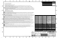
6. <strong>M2</strong> BLANK DRAWING<br />
Discussion: In case of disagreement between the in<strong>for</strong>mation in the <strong>M2</strong> <strong>Blank</strong> Drawing and the<br />
in<strong>for</strong>mation in the text, the in<strong>for</strong>mation in the drawing shall have precedence.
TMT.OPT.SPE.07.005.REL01 Page 16 of 20<br />
SECONDARY MIRROR BLANK SPECIFICATIONS 1/12/2010<br />
Figure 2. Secondary Mirror <strong>Blank</strong> Drawing
TMT.OPT.SPE.07.005.REL01 Page 17 of 20<br />
SECONDARY MIRROR BLANK SPECIFICATIONS 1/12/2010<br />
7. APPENDICES<br />
7.1 CTE SPECIMEN SAMPLING GEOMETRY<br />
Per requirement [SPE-<strong>M2</strong>.BLK-1501] The <strong>M2</strong> <strong>Blank</strong> Supplier shall define a CTE sampling scheme<br />
<strong>for</strong> collection of CTE Specimens that will enable calculation of all the required CTE metrics. A possible<br />
sampling geometry is shown below in Figure 3 <strong>for</strong> illustration only. This particular sampling<br />
geometry is not required, and is provided only as an example. The Z-BLANK direction is as<br />
specified in Figure 2. Secondary Mirror <strong>Blank</strong> Drawing.<br />
Specimen 4<br />
Specimen 5<br />
Z BLANK<br />
Specimen 6<br />
Specimen 3<br />
Layer 1<br />
Specimen 7<br />
Specimen 2<br />
Specimen 1<br />
Specimen 8<br />
Layer 1: sample layer<br />
Layer 2: <strong>Blank</strong><br />
Layer 3: sample layer<br />
Specimen 12<br />
Specimen 13<br />
Specimen 14<br />
Specimen 11<br />
Layer 3<br />
Specimen 15<br />
Specimen 10<br />
Specimen 9<br />
Specimen 16<br />
Specimens from Layers 1 and 3<br />
are used to calculate the CTE of<br />
the <strong>Blank</strong> Material from Layer 2<br />
Figure 3. A possible CTE sampling geometry within a boule or casting<br />
7.2 INSTANTANEOUS CTE MEASUREMENT<br />
For each CTE Specimen, the requirements in Section 3.1.5.3 specify that Instantaneous CTE<br />
calculations be made. The conventional measurement technique would produce ΔL/L data as shown<br />
in Figure 4. The Instantaneous CTE is the first derivative of the ΔL/L curve with respect to<br />
Temperature.
TMT.OPT.SPE.07.005.REL01 Page 18 of 20<br />
SECONDARY MIRROR BLANK SPECIFICATIONS 1/12/2010<br />
Figure 4. ΔL/L and Instantaneous CTE measurement data of a hypothetical CTE Specimen “n”<br />
7.3 CALCULATING SHOP-OP EFFECTIVE CTE AND OPERATING RANGE AVERAGE CTE<br />
7.3.1 Shop-Op Effective CTE<br />
The requirements in Section 3.1.5.4 require calculation of the Shop-Op Effective CTE of each CTE<br />
Specimen over the Shop-Op Temperature Range from 2°C to 20°C. Figure 5 graphically illustrates<br />
the calculation of the Shop-OpEffective CTE <strong>for</strong> each CTE Specimen <strong>for</strong> the <strong>M2</strong> <strong>Blank</strong>.<br />
The Shop-Op Effective CTE of the <strong>M2</strong> <strong>Blank</strong> shall be the average of the Shop-Op Effective CTEs of<br />
all the CTE Specimens.<br />
7.3.2 Operating Range Average CTE<br />
The requirements in Section 3.1.5.5 require calculation of the Operating Range Average CTE of each<br />
CTE Specimen using the Instantaneous CTE measurements of the CTE Specimen. For the<br />
purposes of this specification, Operating Range Average CTEs shall be calculated using<br />
Instantaneous CTE values at the Observatory Temperatures: -5°C, 2°C and 9°C. This is graphically<br />
illustrated in Figure 5 <strong>for</strong> one CTE Specimen.<br />
The <strong>M2</strong> <strong>Blank</strong> Operating Range Average CTE is calculated by averaging the calculated Operating<br />
Range Average CTE values from all the CTE Specimens (calculated only at the Observatory<br />
Temperatures: -5°C, 2°C and 9°C). This is done by summing the CTE Specimen Operating Range<br />
Average CTEs then dividing the sum by the number of CTE Specimens. For the sampling example in<br />
Figure 3, one would use the CTE Specimens in layer 1 and the CTE Specimens in layer 3 to calculate<br />
the Average CTE of the <strong>M2</strong> <strong>Blank</strong>.
TMT.OPT.SPE.07.005.REL01 Page 19 of 20<br />
SECONDARY MIRROR BLANK SPECIFICATIONS 1/12/2010<br />
“n”<br />
Effective CTE (CTE e ) between 2°C and 20°C = 27.2x10 -9 /°C<br />
ΔL/L<br />
curve<br />
Specimen<br />
Instantaneous<br />
CTE, (CTE i ) <strong>for</strong><br />
specimen n<br />
evaluated at -5°C<br />
CTE e,n,2:20C<br />
27.2x10 -9 /°C<br />
CTE i,n,-5C<br />
8.9x10 -9 /°C<br />
CTE i,n,2C<br />
5.6x10 -9 /°C<br />
CTE i,n,9C<br />
17.3x10 -9 /°C<br />
Specimen Average CTE: Average(CTE i,n,-5C ; CTE i,n,2C ; CTE i,n,9C )<br />
= 10.6x10 -9 /°C<br />
Figure 5. Calculation of Shop-Op Effective CTE and Operating Range Average CTE of a hypothetical CTE<br />
Specimen<br />
7.4 CALCULATING CTE AXIAL GRADIENT<br />
Per the requirements specified in Section 3.1.5.7, the <strong>Blank</strong> Supplier is required to make CTE<br />
measurements and calculate CTE Axial Gradient metrics based upon measured data. The Operating<br />
Range Average CTEs of the CTE Specimens, as described above in Section 7.3, are to be used <strong>for</strong><br />
these calculations.<br />
Per requirement [SPE-<strong>M2</strong>.BLK-1501], the <strong>Blank</strong> Supplier is responsible <strong>for</strong> defining a CTE sampling<br />
and measurement scheme that will enable calculation of CTE Axial Gradient. TMT has developed a<br />
spreadsheet tool <strong>for</strong> evaluating candidate sampling schemes, and will provide it to potential <strong>Blank</strong><br />
Suppliers upon request.<br />
The evaluation of CTE Axial Gradient metrics shall be per<strong>for</strong>med as follows. For the purposes of<br />
illustration, the sampling geometry shown above in Figure 3 is used. This particular sampling<br />
scheme is not required, and is provided only as an example.<br />
1. For the <strong>M2</strong> <strong>Blank</strong>, plot the Operating Range Average CTEs <strong>for</strong> the CTE Specimens versus the<br />
axial distance from the center of the convex surface of the <strong>M2</strong> <strong>Blank</strong> to the locations where the<br />
Instantaneous CTE measurements were taken from the CTE Specimens. The Z-<strong>Blank</strong> direction<br />
from Figure 2 shall be used to establish the positive and negative distance directions. The<br />
example shown uses measurements taken from four locations located in layers above and<br />
below the center of the <strong>Blank</strong> (the final locations will be based on the <strong>Blank</strong> Supplier’s specific<br />
sampling plan). Referring to the example shown in Figure 3, to calculate the <strong>Blank</strong> CTE Axial<br />
Gradient of <strong>Blank</strong> material from Layer 2, use the CTE Specimens Operating Range Average<br />
CTEs from Layers 1 and 3 to create 8 data points.
TMT.OPT.SPE.07.005.REL01 Page 20 of 20<br />
SECONDARY MIRROR BLANK SPECIFICATIONS 1/12/2010<br />
2. Per<strong>for</strong>m a linear least squares fit of the data. Calculate the slope of the fit line. This slope is the<br />
CTE Axial Gradient from the set of data. This is illustrated using hypothetical data in Figure 6.<br />
30<br />
CTE Specimen Operating Range Average CTE<br />
(10 -9 / °C)<br />
25<br />
20<br />
15<br />
10<br />
5<br />
y = 35.07x + 17.56<br />
Least-Squares Linear Fit<br />
<strong>M2</strong> <strong>Blank</strong> CTE Axial Gradient:<br />
Slope= 35.07 X 10 -9 /°C/m<br />
0<br />
-0.20 -0.15 -0.10 -0.05 0.00 0.05 0.10 0.15 0.20<br />
Distance from center of <strong>M2</strong> <strong>Blank</strong> (positive in the Z-<strong>Blank</strong> direction)<br />
(m)<br />
Figure 6. Example of CTE Axial Gradient Calculation<br />
3. Choose the orientation of the concave and convex surfaces of the <strong>Blank</strong> to satisfy [SPE-<br />
<strong>M2</strong>.BLK-1560]. I.e., if the measured gradient in the Z <strong>Blank</strong> direction is